Patent application title: Belt sanding attachment tool
Inventors:
Terry Gosschalk (Gleniffer, AU)
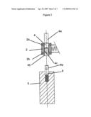
Terence James Walker (Bellingen, AU)
IPC8 Class: AB24B4100FI
USPC Class:
451342
Class name: Abrading frame or mount for hanging rigid, rotary abrading tool
Publication date: 2009-04-30
Patent application number: 20090111363
Inventors list |
Agents list |
Assignees list |
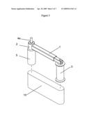
List by place |
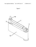
Classification tree browser |
Top 100 Inventors |
Top 100 Agents |
Top 100 Assignees |
Usenet FAQ Index |
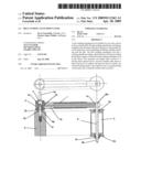
Documents |
Other FAQs |
Patent application title: Belt sanding attachment tool
Inventors:
Terry Gosschalk
Terence James Walker
Agents:
Terry Gosschalk
Assignees:
Origin: GLENIFFER, AU
IPC8 Class: AB24B4100FI
USPC Class:
451342
Abstract:
A belt sanding attachment tool suitable for use with a driver such as a
bench drill, the belt sanding attachment tool being a complete unit and
removable from the driver, and suitable for work operations such as
grinding, polishing, sanding, finishing and the like. The belt sanding
attachment tool has a rotating spindle providing a dual function of
firstly providing the primary support of the whole belt sanding
attachment tool to the driver, and secondly, providing rotary motion to a
driving drum spaced from a second rotatable idler drum to direct and move
an endless belt between the two drums. An outward biasing means is
provided by way of a spring within a telescopic arm to keep the endless
belt in tension.Claims:
1. A belt sanding attachment tool suitable for use with a driver, the belt
sanding attachment tool being a complete unit and removable from the
driver, and suitable for work operations such as grinding, polishing,
sanding, finishing and the like,wherein the belt sanding attachment tool
has a rotating spindle providing a dual function of,firstly providing the
primary support of the whole belt sanding attachment tool to the driver,
andsecondly providing rotary motion to a driving drum spaced from a
second rotatable idler drum to direct and move an endless belt between
the two drums,and an outward biasing means is provided to keep the
endless belt in tension.
2. A belt sanding attachment tool according to claim 1 wherein the outward biasing movement is by a telescopic arm.
3. A belt sanding attachment tool according to claim 1 wherein the outward biasing force is provided by a spring.
4. A belt sanding attachment tool according to claim 1 wherein the tool device is suitable for use with a driver which includes a drilling machine including a motor, a drive spindle, and a drill chuck; the drive drum being operatively connectable to the drill chuck for the dual purpose of driving the drive drum, and supporting the whole assembly.
5. A belt sanding attachment tool according to claim 1 wherein a means is provided to prevent rotation of the assembly, holding the assembly in a fixed working position.
6. A belt sanding attachment tool according to claim 1 wherein a support platen is optionally connectable to the assembly, positioned adjacent to, and behind the working surface of the endless abrasive belt.
7. A belt sanding attachment tool substantially as herein before described with reference to FIGS. 1-7 of the accompanying drawings.
Description:
[0001]This invention is an improved Sanding Belt attachment with
replaceable sanding belts, to be used in a workshop machine such as a
pedestal drill or a similar device.
[0002]This invention provides a telescopic arm with a bearing assembly, drive shaft and drive drum at one end, and a tracking drum at the other. The telescopic arm has a spring fixed within it to provide a suitable force outwards towards the tracking drum.
[0003]The bearing assembly has an upper and lower bearing through which the drive shaft is fixed.
[0004]The upper end of the drive shaft is tightened into the chuck of a pedestal drill, and the lower end of the drive shaft has a threaded hole.
[0005]The drive drum having a male threaded shaft at one end enables it to be fixed and tightened into the threaded hole in the end of the drive shaft. This situation allows the drive drum to be removed and exchanged for drum of a different profile.
[0006]The bearings in the bearing housing are spaced at such a distance apart so as to provide vertical stability at the drive drum end of the telescopic arm.
[0007]At the opposite end of the telescopic arm is the tracking drum. The tracking drum has one bearing in the upper end and one bearing at the lower end. These two bearings allow the tracking drum to rotate freely on its shaft which is fixed on the outer end of the telescopic arm. The shaft that the tracking drum rotates on is slightly extended at the bottom end so as to engage into one of the slots or holes in the drill press table thus creating a solid and stable positioning for the devise in the horizontal plane.
[0008]When the device is attached to the drill press it presents the sanding belt at 90 degrees to the drill press table, allowing many variations of sanding profile to be achieved.
[0009]Included and as part of the device is a suitably shaped metal backing plate with a flatted area. The top edge of the metal plate engages with and is fixed to the telescopic arm. The flatted area of the backing plate is positioned to be behind the working area of the sanding belt between the drive drum and the tracking drum. This enables a flat surface to be worked. The metal plate can easily be removed allowing gentle convex curves to be worked in the same area. At the drive drum end of the device concave sanding and shaping can be achieved. The interchangeable drive drum arrangement adds versatility.
[0010]Included and as part of the device is suitably shaped narrow drive wheel that replaces The drive drum. The outer edge of the wheel has a radius and carries a narrow sanding belt to allow detailed concave sanding.
[0011]FIG. 1. Shows a split side elevation view of the main body assembly of the device according to this invention.
[0012]FIG. 2. Shows the bearing assembly and the attachment of the interchangeable drive drums.
[0013]FIG. 3. Shows the device with the sanding belt ready to be fitted.
[0014]FIG. 4. Shows the device with the sanding belt fitted and ready for work
[0015]FIG. 5. Shows the device with the sanding belt removed and the backing plate in position with its fixing bolt and locking rod.
[0016]FIG. 6. Shows the device with the small drive wheel fitted and the application of a narrow belt.
[0017]FIG. 7. Shows the device attached to a drill press or similar device.
[0018]To assist with understanding the invention, reference will now be made to the accompanying drawings which show examples of the invention.
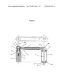
[0019]REFERRING TO FIG. 1 The device shows the telescopic arm 1 with the bearing assembly 2 at one end and the tracking drum 3 at the other. The bearing assembly 2 carries one upper bearing 2a and one lower bearing 2b. The upper end 4a of the drive shaft 4 is tightened into the chuck of the drill press or similar device (refer FIG. 7.) The lower end 4b of the drive shaft 4 having a female thread 4c allows the male threaded end 8a of the drive drum shaft 8 of the drive drum 5 to be fixed in and tightened. This arrangement allows a drive drum to be easily replaced with a drive drum of a different size and profile.
[0020]The tracking drum 3 has an upper bearing 3a and lower bearing 3b to enable it to rotate freely on its shaft 9. The upper end 9a of shaft 9 is fixed to the outer end la of telescopic arm 1. The lower end of shaft 9 has an extension 9b to engage into a hole or slot in the drill table of the pedestal drill or similar device (see FIG. 7).The locking nut 9c holds the tracking drum in its correct alignment. The compressed spring 1b within the telescopic arm 1 provides a suitable outwards force towards the tracking drum 3.
[0021]REFERRING TO FIG. 2 Shows the bearing housing 2 with one upper bearing 2a and one lower bearing 2b. The drive shaft 4 being fixed between the two bearings and with the upper end 4a engaged into the chuck of the pedestal drill is the driving end of the device. The lower end 4b with threaded hole 4c will except the male threaded end 8a of the drive drum shaft 8. The drive drum shaft 8 is permanently fixed to the drive drum 5.
[0022]REFERRING TO FIG. 3 Shows the device in perspective. The telescopic arm 1, the bearing housing 2, the tracking drum 3, the upper end of the drive shaft 4a and the drive drum 5 ready for attachment into the chuck of the drill press. The sanding belt 10 is ready to be assembled between the drive drum and the tracking drum.
[0023]REFERRING TO FIG. 4 Shows the device in perspective with the sanding belt 10 in position between the drive drum 5 and the tracking drum 3 tensioned by the telescopic arm 1. The upper end of the drive shaft 4a is ready for attachment into the chuck of the drill press.
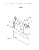
[0024]REFERRING TO FIG. 5 Shows the flat backing plate 11 of a particular shape so as to be assembled onto the telescopic arm 1 and fixed in place with the bolt 12 and locking rod 12a. The bolt 12 will pass through the hole 13 and beneath the telescopic arm 1 before being fixed in position by the locking rod 12a. The backing plate 11 will sit behind the sanding belt 10.
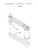
[0025]REFERRING TO FIG. 6 Shows the alternative narrow drive drum 14 with the narrow belt 15 for use with detailed concave shaping and sanding.
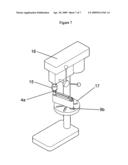
[0026]REFERRING TO FIG. 7 Shows the device with the drive shaft upper end 4a fixed into the chuck 15 of the drill press 16. The lower end 9b of the tracking drum 3 in position through a hole or slot in the drill table 17.
[0027]Finally, it is to be understood that the inventive concept in any of its aspects can be incorporated in many different constructions so that the generality of the preceding description is not to be superseded by the particularity of the attached drawings. Various alterations, modifications and/or additions may be incorporated into the various constructions and arrangements of parts without departing from the spirit or ambit of the invention.
User Contributions:
comments("1"); ?> comment_form("1"); ?>Inventors list |
Agents list |
Assignees list |
List by place |
Classification tree browser |
Top 100 Inventors |
Top 100 Agents |
Top 100 Assignees |
Usenet FAQ Index |
Documents |
Other FAQs |
User Contributions:
Comment about this patent or add new information about this topic:
Images included with this patent application:
 |  |
 |  |
 |  |
 |  |
| New patent applications in this class: | |
| Date | Title |
|---|---|
| 2016-06-02 | Holding device for a grinding means |
| 2016-05-12 | Adapter |
| 2012-08-23 | Position adjustment mechanism of grinding wheels |
| 2012-07-05 | Power tool |
| 2011-08-11 | Power tool packing apparatus |
| New patent applications from these inventors: | |
| Date | Title |
|---|---|
| 2009-04-09 | Sanding disk tool |
| 2009-04-09 | Flail sanding tool |
| 2009-04-09 | Powered line trimmer attachment |
| Top Inventors for class "Abrading" | |
| Rank | Inventor's name |
|---|---|
| 1 | Boguslaw A. Swedek |
| 2 | Hung Chih Chen |
| 3 | Jeffrey Drue David |
| 4 | Dominic J. Benvegnu |
| 5 | Chien-Min Sung |