Patent application title: Charger module for an internal combustion engine
Inventors:
Ralf Doring (Gerolfing, DE)
Joerg Riegner (Strahwald, DE)
Jens-Uwe Kaulbach (Lenting, DE)
Ralph Hollmig (Ingolstadt, DE)
Assignees:
Audi AG
IPC8 Class: AF02B2904FI
USPC Class:
123563
Class name: Charge forming device (e.g., pollution control) supercharger intercooler
Publication date: 2009-03-19
Patent application number: 20090071450
Inventors list |
Agents list |
Assignees list |
List by place |
Classification tree browser |
Top 100 Inventors |
Top 100 Agents |
Top 100 Assignees |
Usenet FAQ Index |
Documents |
Other FAQs |
Patent application title: Charger module for an internal combustion engine
Inventors:
Ralf Doring
Joerg Riegner
Jens-Uwe Kaulbach
Ralph Hollmig
Agents:
Novak Druce & Quigg LLP
Assignees:
Audi AG
Origin: WASHINGTON, DC US
IPC8 Class: AF02B2904FI
USPC Class:
123563
Abstract:
The invention relates to a charger module (1) for an internal combustion
engine, comprising a mechanical charger (2) and two charge coolers (3,
4), mounted downstream of the charger (2), for cooling the compressed
charge air. The aim of the invention is to reduce the costs for producing
such a charger module without impairing the rigidity or structural
stability of the charger module (1). For this purpose, the charger (2)
and the two charge coolers (3, 4) are inserted in a common housing (5)
which surrounds the charger (2) and the two charge coolers (3, 4) at
least on the bottom side and on two opposite sides.Claims:
1. Charger module for an internal combustion engine, comprising a
mechanical charger and two charge air coolers downstream from the charger
for cooling the compressed charge air, wherein the charger and the two
charge air coolers are disposed in a common housing that encloses the
charger and the two charge air coolers at least on the bottom and on two
opposite sides.
2. The charger module according to claim 1, wherein the housing is produced from light metal.
3. The charger module according to claim 1 wherein the housing is produced by means of a sand-casting process.
4. The charger module according to claim 1 wherein the charger is arranged in the center between the two charge air coolers.
5. The charger module according claim 1 wherein the housing further encloses an air distributor that is arranged between the charger and the charge air coolers.
6. The charger module according to claim 5, wherein the air distributor is arranged above the charger and the two charge air coolers.
7. The charger module according to claim 1 wherein the housing also encloses a bypass for partial-load adjustment.
8. The charger module according to claim 7, wherein the bypass is arranged above the charger.
9. The charger module according to claim 1 wherein the housing is equipped on one of its faces with an opening for inserting the charger.
10. The charger module according to claim 9 wherein the housing is equipped on one of its faces with an air intake opening.
11. The charger module according to claim 10, wherein the air intake opening and the opening to insert the charger are arranged on opposite faces of the housing.
12. The charger module according to claim 1 wherein the housing has a large number of air outlet openings on its bottom.
13. The charger module according to claim 12, wherein the air outlet openings are arranged below the two charge air coolers.
14. The charger module according to claim 1 wherein cooling water flows through the charge air coolers parallel to the longitudinal sides of the housing, and charge air flows in cross-current from the top downward.
15. The charger module according to wherein one of the charge air coolers and the housing is provided on a face with connections for supply and removal of cooling water.
16. The charger module according to claim 1 wherein the housing is sealed on its top by an air distributor cover.
17. The charger module according to claim 16, wherein the air distributor cover is designed as a unit with a bottom and side walls of the housing.
18. The charger module according to claim 16 wherein the housing is equipped on one of its faces with openings for inserting the two charge air coolers.
19. The charger module according to claim 16, wherein the air distributor cover is designed as a screw cap and closes at least one opening in inserting the charge air coolers.
20. The charger module according to claim 1 wherein the charge air coolers are produced in light sheet-metal design.
21. An internal combustion engine with an engine block, two rows of V-shaped cylinders arranged in the engine block and two cylinder heads fastened above the rows of cylinders on the engine block, including a mechanical charger and two charge air coolers downstream from the charger for cooling the compressed charge air wherein the charger and the two charge air coolers are disposed in a common housing that encloses the charger and the two charge air coolers at least on the bottom and on two opposite sides thereof.
22. The internal combustion engine according to claim 1, wherein the housing is supported below the two charge air coolers with its bottom on the cylinder heads.
23. The internal combustion engine according to claim 19 wherein the housing is tightly screwed onto the cylinder heads.
24. The internal combustion engine according to claim 19 wherein the charger module bridges an intermediate space between the two cylinder heads.
25. The internal combustion engine according to claim 19 wherein the charger is connected via a belt drive with the crankshaft of the internal combustion engine.
Description:
[0001]The invention relates to a charger module according to the preamble
of Claim 1 as well as an internal combustion engine according to the
preamble of Claim 18.
[0002]In the applicant's German Patent Application DE 102004049027.9 dated Oct. 8, 2004, which was still unpublished on the application date of this patent application, a charger module of the above-mentioned type is already described for a V-type internal combustion engine in which the two charge air coolers that are arranged on the left and the right of the charger are braced on two anchoring plates that project laterally over a housing of the charger in order to stiffen the module and thus to reduce fault liability caused by operationally-induced vibration. The charge air coolers are held there by a cover that is designed as an air distributor, and said cover is screwed together with the anchoring plates through the housing of the charge air cooler.
[0003]To impart stability that is sufficient for clamping between the anchoring plate and the air distributor cover to the charge air coolers, and to ensure an airtight connection to the anchoring plate or to the air distributor cover on the top and bottom thereof, the charge air coolers must have a-stable cast housing with a flat sealing flange on the top and bottom, which produces significant additional costs in production in comparison to a charge air cooler that is produced in a light sheet-metal design.
[0004]Based on this, the object of the invention is to reduce the production costs in a charger module of the above-mentioned type without impairing the rigidity or the structural strength of the charger module.
[0005]This object is achieved according to the invention in that the charger and the two charge air coolers are used in a common housing, which surrounds the charger and the two charge air coolers at least on the bottom and on two opposite sides. By using a stable, common housing for the charger and the two charge air coolers, the two charge air coolers in light design can be produced from sheet metal and can be used in the housing, by which not only can the production costs of the entire charger module be reduced, but also the heat transfer from the charge air to the cooling water can be improved. Moreover, the common housing imparts to the charger module a comparatively high stability and rigidity, by which a vibration-free fastening to the internal combustion engine is made possible and thus the acoustics are improved by reducing vibration-induced noise generation.
[0006]Since the housing must have a relatively complicated shape with a series of openings in various sides because of the number of components housed within, it is preferably produced in the sand-casting process from light metal.
[0007]According to a preferred embodiment of the invention, the charger module is used in V-type internal combustion engines, which have an engine block, two rows of V-shaped cylinders arranged in the engine block, and two cylinder heads that are fastened above the rows of cylinders over the engine block, the charger module bridging an intermediate space between the cylinder heads of the two rows of cylinders. This arrangement ensures the connection of the charger module to the two cylinder heads and the thus enabled double fastening of the charger module to the engine block for an especially vibration-free design.
[0008]Advantageously, the charger in the charger module is arranged in the center between the two charge air coolers, the charge air that is compressed by the charger flowing to an air distributor, which is arranged on the top of the charger module between the charger and the charge air coolers and which preferably is integrated also in the housing of the charger module, to the two charge air coolers and from there downward through the respective cylinder head into the cylinder; hence, the response behavior can be considerably improved by the extremely short air passages between the charger and the cylinder heads.
[0009]Especially high stability of the fastening and especially short air passages are thus achieved in that the housing of the charger module below the two charge air coolers is supported directly with its bottom on the two cylinder heads and is tightly screwed on the latter or on hinged flanges onto the cylinder heads, a large number of air outlets on the bottom of the housing emptying directly into corresponding air channels in the cylinder heads or hinged flanges that lead to the cylinders.
[0010]The arrangement of the charger in the center between the two charge air coolers also facilitates the driving of the charger by means of the crankshaft of the internal combustion engine, which preferably is connected via a belt drive to a drive shaft of the charger that projects over a face of the housing.
[0011]In addition to the charger and the two charge air coolers, the housing may advantageously also comprise a bypass for partial-load adjustment, by which a portion of the air suctioned off from the charger can be returned to an air intake of the charger and sent to the circuit by the charger. The bypass is preferably arranged above the charger on the top of the housing, as a result of which the air passage through the bypass can also be kept short.
[0012]To mount the charger and the two charge air coolers in the housing, the latter is preferably equipped with openings through which the charger and the two charge air coolers can be introduced or inserted into the housing. The opening for inserting the charger is advantageously arranged on one of the two faces of the housing, preferably on the face that is opposite to a charge air intake opening of the charger.
[0013]According to a first alternative, however, the two charge air coolers can be inserted into the housing from above, and in this case, said housing is advantageously equipped with at least one opening on its top. After the insertion of the respective charge air cooler, the opening is sealed, while according to a preferred embodiment of the invention, a single screw cap is provided that extends over the entire width of the housing and forms the air distributor, which distributes the air that is compressed in the charger to the two charge air coolers.
[0014]According to a second preferred alternative, the two charge air coolers are each inserted into the housing through a front opening. This alternative makes a fastening of cooling water connections to the housing of the charger module unnecessary, since the cooling water connections can be applied on the front end itself of the charge air cooler that is adjacent to the insertion opening, so that they lie outside of the housing, since the charge air cooler has been inserted completely into the insertion opening. In this latter case, the housing is sealed on its top preferably by a cover that is designed with a bottom and side walls of the housing as a unit and said cover is formed together with the remainder of the housing during pouring and is advantageously also designed inside as an air distributor.
[0015]Below, the invention will be explained in greater detail based on two embodiments that are depicted in the drawing. Here:
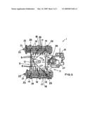
[0016]FIG. 1: shows a perspective top view of a charger module for a V-type internal combustion engine with a mechanical charger, two charge air coolers and a screwed-in air distributor cover;
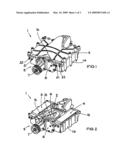
[0017]FIG. 2: shows a somewhat enlarged view according to claim FIG. 1, but with a removed air distributor cover;
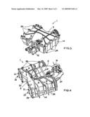
[0018]FIG. 3: shows a perspective top view of the charger module from another line of sight;
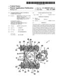
[0019]FIG. 4: shows a perspective top view of a modified charger module with an air distributor jacket that is designed as an integral part of the housing, but without the charger;
[0020]FIG. 5: shows a top view of the charger module from FIG. 4, but with a partially cut-away air distributor cover.
[0021]As can best be seen from FIG. 2, the charger module 1, shown in the drawing, for an internal combustion engine that is designed as a 6-cylinder V-engine (not shown) essentially consists of a mechanical charger 2 and two charge air coolers 3, 4, arranged on both sides of the charger 2, and said coolers are installed in a common housing 5.
[0022]The mechanical charger 2 is a compressor that operates according to the displacement principle with or without inner compression, which can be designed either as a Roots compressor or as a screw compressor of the Lysholm type.
[0023]The charger 2 comprises two rotary pistons or rotors (not shown) with parallel axes of rotation, which are arranged beside one another in a cavity 6 that is surrounded by the housing 5.
[0024]The rotary pistons or rotors are connected via a synchromesh gear (not shown) to a compressor-drive shaft 7 that projects over a sealing cover 8 on a front end face 9 of the housing 5 and is driven by means of a drive belt (not shown) from the crankshaft of the internal combustion engine. The drive of the charger 2 causes charge air to be aspirated through an air intake opening 10, connected via a throttle to an air filter and an intake manifold (not shown) of the internal combustion engine, into the charger 2 on the rear end face 11 of the housing 5; from the charger, it is ejected again after passing between the rotary pistons or rotors and a boundary wall of the cavity 6 through an air outlet opening 12 that is arranged on its top, as is best shown in FIG. 5. An air distributor 13, which divides air stream A, exiting from the air outlet opening 12, into partial streams B and then, within the housing 5, directs said partial streams uniformly to both sides to the charge air coolers 3, 4, is located above the air outlet opening 12.
[0025]In the charger module 2 that is shown in FIGS. 1 to 3, the housing 5 is designed in two parts, it essentially consisting of a base part 14 that accommodates the charger 2 and the two charge air coolers 3, 4 and a screw cap that forms the air distributor 13, both of which are produced from aluminum in the sand-casting process.
[0026]On its front face 9, the base part 14 of the housing 5 has an insertion opening for inserting the charger 2, which is closed after the sealing cover 8 is inserted. The base part 14 further has two recesses 15, open at the top, in which the two charge air coolers 3, 4 are inserted from above into the base part of the housing 14, before the air distributor cover 13 is screwed on, which then extends over the entire top of the housing 5 and closes the insertion openings on the tops of the recesses 15.
[0027]In the charger module 2 that is shown in FIGS. 4 and 5, the housing 5 that is also produced in the sand-casting process from aluminum, however, is designed in one piece with an integral air distributor cover 13 and is equipped on its front face 29 with two insertion openings 16, by which the charge air coolers 3, 4 can be inserted from the front into the housing 5.
[0028]As is best shown in FIG. 5, the two charge air coolers 3, 4 that are made of aluminum in a light design in each case have a cooler housing 17 that is matched to the shape of the recesses 15 or insertion openings 16, said cooler housing being open on its top and bottom and enclosing a somewhat rectangular vertical air channel 18 in cross-section. The air channel 18 extends from an upper air intake that communicates with the air outlet opening 12 of the charger 2 through the air distributor 13 up to an air outlet that is arranged on the bottom of the cooler housing 17, where the cooled charge air moves directly into air channels in the cylinder head that extend onward through a number of air outlet openings 19 in the bottom of the housing 5 that corresponds to the number of cylinders of the internal combustion engine. The cooler housings 17 in each case contain a large number of parallel cooling fins 20, which are arranged in longitudinal direction of the charge air coolers 3, 4, i.e., parallel to the compressor shaft of the charger 2, between opposite front boundary walls of the air channel 18, and cooling water flows through them. The latter is fed into the cooling fins 20 by a cooling water intake 21 that is arranged in the front face of the housing 5 and exits again from the coolers 3, 4 through a cooling water outlet 22 that is arranged next to it or below it.
[0029]While the cooling water intake 21 and the cooling water outlet 22 are integrated into the charger module 1 in FIGS. 1 to 3 in the housing 5, they form a part of a sealing cover 23, sealing the insertion opening 16 and screwed on with the housing 5, on the front ends of the charge air coolers 3, 4 in the charger module 1 in FIGS. 4 and 5.
[0030]After assembly, the charger module 1 is mounted on the two cylinder heads of the internal combustion engine, the bottom of the housing 5 lying below the charge air coolers 3, 4 against the tops of two hinged flanges (CVTS flanges) that sit on the cylinder heads of the internal combustion engine, and the air outlet openings 19 being aligned with corresponding air inlet openings in the hinged flanges. Fastening of the charger module is done with the aid of fastening screws 24, which are screwed into threaded holes of the hinged flanges by through-holes 25 in the housing 5.
[0031]As best shown in FIG. 4 with an arrow C in dashes, the housing 5 also encloses a bypass for partial-load adjustment that is arranged below the air distributor cover 13, said bypass extending between the charger 2 and the air distributor cover 13 up to the rear face 11 of the housing 5, where it can be connected, if necessary, with the aid of a pivotable bypass flange 26 (FIG. 5), to an add-on part 27 that is flanged on the housing 5, with an air intake channel between the air inlet opening 11 and the charger 2, to move a portion of the charge air in the circuit through the charger 2.
REFERENCE SYMBOL LIST
[0032]1. Charger module [0033]2. Charger [0034]3. Charge air cooler [0035]4. Charge air cooler [0036]5. Housing [0037]6. Cavity [0038]7. Drive shaft [0039]8. Sealing cover [0040]9. Face of the housing [0041]10. Air intake opening [0042]11. Face of the housing [0043]12. Air outlet opening [0044]13. Air distributor cover [0045]14. Housing base part [0046]15. Recesses [0047]16. Insertion openings [0048]17. Cooler housing [0049]18. Air channel [0050]19. Air outlet openings [0051]20. Cooling fins [0052]21. Cooling water intake [0053]22. Cooling water outlet [0054]23. Sealing cover [0055]24. Fastening Screws [0056]25. Through-holes [0057]26. Bypass flap [0058]27. Add-on part [0059]A, B, C Arrows showing air flow
User Contributions:
comments("1"); ?> comment_form("1"); ?>Inventors list |
Agents list |
Assignees list |
List by place |
Classification tree browser |
Top 100 Inventors |
Top 100 Agents |
Top 100 Assignees |
Usenet FAQ Index |
Documents |
Other FAQs |
User Contributions:
Comment about this patent or add new information about this topic:
Images included with this patent application:
 |  |
 |  |
| Similar patent applications: | |
| Date | Title |
|---|---|
| 2013-05-30 | Controller for internal combustion engine |
| 2013-05-30 | Crankshaftless internal combustion engine |
| 2013-05-30 | Crankshaftless internal combustion engine |
| 2013-05-30 | Ancillary device for enhancing engine fuel combustion efficiency |
| 2010-10-14 | Internal combustion engine |
| New patent applications in this class: | |
| Date | Title |
|---|---|
| 2018-01-25 | Cooling control system for internal combustion engine |
| 2016-05-26 | Intake-air cooling apparatus for vehicle |
| 2016-02-11 | Charge air cooling system and charge air cooler for the same |
| 2015-02-12 | Cooling system and associated operating method |
| 2014-10-16 | Combustion control for combustion engines |
| New patent applications from these inventors: | |
| Date | Title |
|---|---|
| 2016-04-28 | Method and control system for operating at least one apparatus that is arranged in a building |
| Top Inventors for class "Internal-combustion engines" | |
| Rank | Inventor's name |
|---|---|
| 1 | Ross Dykstra Pursifull |
| 2 | Gopichandra Surnilla |
| 3 | Joseph Norman Ulrey |
| 4 | Thomas G. Leone |
| 5 | Chris Paul Glugla |