Patent application title: LID STABILIZING APPARATUS
Inventors:
Ronald E. Smith (Yakima, WA, US)
IPC8 Class: AE02D2914FI
USPC Class:
404 25
Class name: Road structure, process, or apparatus pavement vault cover-closure
Publication date: 2009-03-05
Patent application number: 20090060654
atus is principally directed to a structure which
will resist a force on a lid which will tend to dislodge the lid from the
structure which it covers. Of particular interest is the lid covering
municipal water valve structures where such lids are repeatedly struck by
vehicular traffic and are dislodged and thrown into the street. The
downwardly extending rod with stabilizing and, where desired,
n-stabilizing disks, will be in friction or near friction contact with
the pipe which is upwardly directed from a valve accessed from the street
surface. This friction or near friction contact will resist the
dislodging of the valve lid.Claims:
1. A lid stabilizing apparatus (1) comprising:a. at least one elongated
rod (100) having a first end (110) and a second end (120); the at least
one elongated rod (100) generally rigid and composed of metals, plastics,
carbon fiber materials or other rigid materials;b. a lid (200) having a
top side (210) and a bottom side (220); a lid aperture (250), centrally
positioned from the top side (210) to the bottom side (220); the at lest
one elongated rod (100) received at the first end (110) by the lid
aperture (250) at the top side (210) or the bottom side (220) and affixed
to the lid (200) by lid-rod affixing means (230) to immovably
interconnect the lid (200) and the rod (100); the lid (200) has a major
diameter (240) and is generally circular; the lid (200) generally planar
and formed of rigid materials including metals, plastics, carbon fiber
materials or other rigid materials;c. a lid sealing ring (290) having a
lid sealing ring major diameter (295) is generally circular and
downwardly extends from the lid bottom side (220); the lid sealing ring
(290) is centrally positioned relative to the lid aperture (250); the lid
sealing ring major diameter (295) is aligned with the lid major diameter
(240) and has a lid sealing ring major diameter length D6 (297) which is
less than the lid major diameter length D1 (247);d. a lid first sealing
ring (260) having a first sealing ring major diameter (265) is generally
circular and downwardly extends from the lid bottom side (220); the lid
first sealing ring (260) centrally positioned relative to the lid
aperture (250); the first sealing ring major diameter (265) aligned with
the lid major diameter (240); the lid first sealing ring major diameter
(260) has a first sealing ring major diameter length D2 (267) which is
less than the lid sealing ring major diameter length D6 (297);e. a lid
second sealing ring (280) having a second sealing ring major diameter
(285) is generally circular and downwardly extends from the lid bottom
side (220); the lid second sealing ring (280) centrally positioned
relative to the lid aperture (250); the second sealing ring major
diameter (285) aligned with the lid major diameter (240); the second
sealing ring major diameter (285) has a second sealing ring major
diameter length D3 (287) which is less than the first sealing ring major
diameter length D2 (267);f. a lid first annulus (275) is formed between
the lid sealing ring (290) and the lid first sealing ring (260); a lid
annulus (270) is formed between the lid first sealing ring (260) and the
lid second sealing ring (280); lid sealing ring (290), lid first sealing
ring (260) and lid second sealing ring (280) are generally formed from a
machining, molding or casting process from metals, plastics, carbon fiber
materials or other rigid materials;g. at least one stabilizing disk (300)
having a stabilizing disk top side (310) and a stabilizing disk bottom
side (320); a stabilizing disk aperture (350) centrally positioned from
the stabilizing disk top side (310) to the stabilizing disk bottom side
(320); the at lest one elongated rod (100) received at the second end
(120) by the stabilizing disk aperture (350) at the top side (320) and
immovably affixed to the at least one stabilizing disk (300) by
stabilizing disk-rod affixing means (330); the at least one stabilizing
disk (300), at the bottom side (320), is beveled, with a stabilizing
disk-bevel (335) most distal from the stabilizing disk aperture (350);
the at least one stabilizing disk (300) has a stabilizing disk major
diameter (340) and is generally circular; the stabilizing disk major
diameter (340) has a stabilizing disk major diameter length D4 (347)
which is less than the lid major diameter length D1 (247) and generally
less than the first sealing ring major diameter length D2 (347);h. at
least one n-stabilizing disk (400) having a n-stabilizing disk top side
(410) and a n-stabilizing disk bottom side (420); the n-stabilizing disk
(400) having a n-stabilizing disk major diameter(440) which has a
n-stabilizing disk major diameter length D5 (447) which is generally
equal to the length of the stabilizing disk major diameter length D4
(347); a n-stabilizing disk aperture (450) from the n-stabilizing disk
top side (410) to the n-stabilizing disk bottom side (420); n-stabilizing
disk spacing (460) between the stabilizing disk bottom (320) and the
n-stabilizing disk top (410); n-stabilizing disk-rod affixing means (430)
immovably affixing the n-stabilizing disk (400) and the rod (100) may be
by a nut (430) received by rod threads (130) at the n-stabilizing disk
top side (410) and a nut (430) received by rod threads (130) at the
n-stabilizing disk bottom side (420); the at least one stabilizing disk
(300) and the at least one n-stabilizing disk (400) generally planar and
formed from rigid materials including metals, plastics, carbon fiber
materials and other rigid and semi-rigid materials including rubber
impregnated cork and poly-foams such as polyurethane;I. the at least one
elongated rod (100) extending outwardly from the lid bottom side (220)
and immovably affixed, by lid-rod affixing means, at or proximal to the
second end (120) to the at least one stabilizing disk (300); the at least
one elongated rod (100) generally orthogonal to the lid (200) and
generally orthogonal to the at least one stabilizing disk (300);j. the
lid (200) having a lid-rod affixing means (230) to immovably affix the
lid (200) and the rod (100); the lid-rod affixing means (230) generally
centrally positioned relative to the lid top side (210) and the lid
bottom side (220); the lid-rod affixing means (230) including a centrally
positioned lid aperture (250) from the top side (210) to the bottom side
(220); the lid aperture (250) may be threaded to receive the rod (100)
having threads (130); the rod (100) at the first end (110) sized to pass
through the lid aperture (250) to be secured by a lid nut (230) at the
lid top side (210) and a lid nut (230) at the lid bottom side (220);
alternatively the elongated rod (100) may be welded, glued or other
affixed by immovable affixing means to the lid (200) to prevent movement
between the rod (100) and the lid (200),k. the at least one stabilizing
disk having a stabilizing disk bevel (335) at the stabilizing disk top
(310) and or stabilizing disk bottom (320) distal from the stabilizing
disk aperture (350); the at least one n-stabilizing disk having a
stabilizing disk bevel (435) at the n-stabilizing disk top (410) and or
n-stabilizing disk bottom (420) distal from the n-stabilizing disk
aperture (450);l. the lid (200) at the lid bottom side (220) sized to
cover a valve housing (500).
2. A lid stabilizing apparatus (1) comprising:a. at least one elongated rod (100) having a first end (110) and a second end (120);b. a lid (200) having a top side (210), a bottom side (220); the at least one elongated rod (100) is immovably affixed centrally to the lid (200), by lid-rod affixing means (230), at the lid bottom (220); the lid (200) is generally circular and has a major diameter (240); the rod (100) extends outwardly from the bottom side (220);c. an at least one stabilizing disk (300) has a stabilizing disk top side (310) and a stabilizing disk bottom side (320); the at least one elongated rod (100) is immovably affixed at or proximal to the second end (120) to the stabilizing disk (300) at the top side (310) and or at the top side (310) and the bottom side (320) by stabilizing disk-rod affixing means (330); the at least one stabilizing disk (300) is distal to the lid (200); the at least one stabilizing disk (300) has a stabilizing disk major diameter (340) and is generally circular; the stabilizing disk major diameter (340) has a stabilizing disk major diameter length D4 (347) which is less than the a lid major diameter length D1 (247).
3. The apparatus of claim 2 further comprising:a. a lid aperture (250), centrally positioned from the top side (210) to the bottom side (220); the at lest one elongated rod (100) received at the first end (110) by the lid aperture (250) at the top side (210) or the bottom side (220) and affixed to the lid (200) by lid-rod affixing means (230) to immovably interconnect the lid (200) and the rod (100); the at least one elongated rod (100) is generally rigid and composed of metals, plastics, composites or other rigid materials;b. the lid (200) is generally planar and formed of rigid materials including metals, plastics, carbon fiber materials or other rigid materials;c. the stabilizing disk (300) has a stabilizing disk aperture (350) centrally positioned from the stabilizing disk top side (310) to the stabilizing disk bottom side (320); the rod (100) is received at the second end (120) by the stabilizing disk aperture (350) at the stabilizing disk top side (310) and or bottom side (320);d. at least one n-stabilizing disk (400) has a n-stabilizing disk top side (410) and a n-stabilizing disk bottom side (420); the at lest one elongated rod (100), extending outwardly from the at least one stabilizing disk bottom (320), is immovably affixed by n-stabilizing disk-rod affixing means (430) at or proximal to the second end (120) to the n-stabilizing disk (400) at the top side (420);e. the n-stabilizing disk (400) has a n-stabilizing disk major diameter(440) which has a n-stabilizing disk major diameter length D5 (447) which is generally equal to the length of the stabilizing disk major diameter length D4 (347).f. the lid (200) at the lid bottom side (220) and lid major diameter length D1 (247) is sized to cover a valve box or housing (500); the stabilizing disk (300) and at least one n-stabilizing disk (400) are sized to be received into a valve box (500).
4. The apparatus of claim 3 further comprising:a. the at least one elongated rod (100) is generally orthogonal to the lid (200) and generally orthogonal to the at least one stabilizing disk (300) and to the at least one n-stabilizing disk (400);b. the lid aperture (250) may be threaded to receive the rod (100) having threads (130); the rod (100) at the first end (110) is sized to pass through the lid aperture (250) to be secured by lid-rod affixing means (230) including by a lid nut (230) at the lid top side (210) and a lid nut (230) at the lid bottom side (220); alternatively the elongated rod (100) may be welded, glued or other affixed by immovable affixing means to the lid (200) to prevent movement between the rod (100) and the lid (200);c. the at least one stabilizing disk (300), at the top side (310) and or the bottom side (320), is beveled with a stabilizing disk-bevel (335) most distal from the stabilizing disk aperture (350); the at least one stabilizing disk (300) has a stabilizing disk major diameter (340) and is generally circular; the stabilizing disk major diameter (340) has a stabilizing disk major diameter length D4 (347) which is less than the lid major diameter length D1 (247) and generally less than the first sealing ring major diameter length D2 (347);d. the at lest one elongated rod (100), extending outwardly from the at least one stabilizing disk bottom (320), is received by an n-stabilizing disk aperture (450) and immovably affixed by n-stabilizing disk affixing means (430) at or proximal to the second end (120) at the n-stabilizing disk top side (420); a n-stabilizing disk spacing (460) between the stabilizing disk bottom (320) and the n-stabilizing disk top (410);e. the at least one stabilizing disk (300) and the at least one n-stabilizing disk (400) are generally planar and circular and formed from rigid materials including metals, plastics, carbon fiber materials and other rigid and alternatively formed from semi-rigid materials including rubber impregnated cork and poly-foams such as polyurethane;f. at least one lid sealing ring (290) having a lid sealing ring major diameter (295) downwardly extends from the lid bottom side (220); the lid sealing ring (290) is centrally positioned relative to the lid aperture (250); the lid sealing ring major diameter (295) is aligned with the lid major diameter (240) and has a lid sealing ring major diameter length D6 (297) which is less than the lid major diameter length D1 (247);g. the at least one stabilizing disk (300) and the at least one n-stabilizing disk (400) sized to provide a friction or near friction engagement with a valve box (500).
5. The apparatus of claim 4 further comprising:a. the n-stabilizing disk-rod affixing means (430) immovably affixes the n-stabilizing disk (400) and the rod (100) which may be by a nut (430) received by rod threads (130) at the n-stabilizing disk top side (410) and a nut (430) received by rod threads (130) at the n-stabilizing disk bottom side (420);b. the at least one n-stabilizing disk may have a stabilizing disk bevel (435) at the n-stabilizing disk top (410) and or n-stabilizing disk bottom (420) distal from the n-stabilizing disk aperture (450); the n-stabilizing disk bevel (435) functions to lessen the difficulty in extracting the Lid Stabilizing Apparatus (1) from a valve box (500) in order to gain access to a valve or other structure;c. the n-stabilizing disk spacing (460) between the stabilizing disk bottom (320) and the n-stabilizing disk top (410) is in the range of a distance equal to the major diameter of the valve box (567) to a distance of zero inches (0.0");d. a lid first sealing ring (260) having a first sealing ring major diameter (265) downwardly extends from the lid bottom side (220); the lid first sealing ring (260) is centrally positioned relative to the lid aperture (250); the first sealing ring major diameter (265) aligned with the lid major diameter (240) and the lid first sealing ring major diameter (260) has a first sealing ring major diameter length D2 (267) which is less than the lid sealing ring major diameter length D6 (297);e. a lid second sealing ring (280) has a second sealing ring major diameter and downwardly extends from the lid bottom side (220); the lid second sealing ring (280) centrally positioned relative to the lid aperture (250); the second sealing ring major diameter (285) aligned with the lid major diameter (240) and the second sealing ring major diameter (285) has a second sealing ring major diameter length D3 (287) which is less than the first sealing ring major diameter length D2 (267); a lid first annulus (275) is formed between the lid sealing ring (290) and the lid first sealing ring (260); a lid annulus (270) is formed between the lid first sealing ring (260) and the lid second sealing ring (280); the lid sealing ring (290), lid first sealing ring (260) and lid second sealing ring (280) are generally formed from a machining, molding or casting process from metals, plastics, carbon fiber materials or other rigid materials;f. the lid sealing ring (290), the lid first sealing ring (260) and the lid second sealing ring (280) are generally circular.Description:
FIELD OF THE INVENTION
[0001]This invention relates to an apparatus which covers the open end of a tube, as a lid, and resists being dislodged. The invention more specifically relates to an apparatus which covers a tubular access enclosure providing access to structure including a valve. The invention relates to an apparatus covering the open end of a valve box including an underground valve housing.
BACKGROUND OF THE INVENTION
[0002]Municipal services include water and other services where pipe and valves, located beneath the surface of a street, are primary components of the service. Underground valve housings are covered with a cap or cover which is subject to vehicular traffic. Such traffic frequently dislodges valve housing covers allowing debris into the housing and causing damage to the housing and cover. Devices which relate to covering or enclosing underground tubular structures include U.S. Pat. No. 5,253,952 to Selway; U.S. Pat. No. 5,240,032 to Mizioch; U.S. Pat. No. 6,449,908 to Gagas; U.S. Pat. No. 6,036,401 to Morina et al. Devices which relate to structures otherwise having similarities to the invention herein include U.S. Pat. No. 22,535 to Willloughby; U.S. Pat. No. 6,488,440 to Hill; U.S. Pat. No. 4,101,154 to Kagstrom; U.S. Pat. No. 6,584,734 to Mihalicz et al; U.S. Pat. No. 5,403,116 to Brewer; U.S. Pat. No. 5,154,681 to Denny; and U.S. Pat. No. 5,607,379 to Scott.
[0003]The patents referred to herein are provided herewith in an Information Disclosure Statement in accordance with 37 CFR 1.97.
SUMMARY OF THE INVENTION
[0004]The lid stabilizing apparatus (1) comprises a rod (100) immovably interconnected with a lid (200) at a lid aperture (250). The rod (100) downwardly extends from the lid (200) and is immovably affixed to a stabilizing disk (300) at a stabilizing disk aperture (350); the rod may as well extend downwardly from the stabilizing disk (300) and there be received, by at least one n-stabilizing disks (400) at a n-stabilizing disk aperture (450) and there be immovably affixed to the at least one n-stabilizing disk (400).
[0005]The lid (200) has a lid major diameter (240) with a lid major diameter length D1 (247). The stabilizing disk (300) has a stabilizing disk major diameter (340) having a stabilizing disk major diameter length D4 (347) which is generally less in length then that of the lid major diameter length D1 (247). Additionally, there may be at least one n-stabilizing disks (400) having a n-stabilizing disk major diameter length D5 which is generally equal in length to that of the stabilizing disk major diameter length D4 (347).
[0006]The lid (200) may be formed at a water valve cover as found in municipal water systems generally in the middle of a street. The stabilizing disk (300) and possibly at least one n-stabilizing disk (400), extending downwardly from the lid (200) are generally of a diameter which will be either in a friction or near friction engagement with the valve pipe extending upwardly from a municipal water valve to the surface of a street. The stabilizing disk (300) and, where used, the at least one n-stabilizing disk (400) will resist forces tending to dislodge a water valve lid (200) or cover when struck by vehicular traffic.
BRIEF DESCRIPTION OF THE DRAWINGS
[0007]The foregoing and other features and advantages of the present invention will become more readily appreciated as the same become better understood by reference to the following detailed description of the preferred embodiment of the invention when taken in conjunction with the accompanying drawings, wherein:
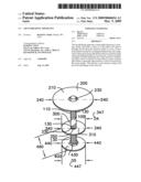
[0008]FIGS. 1 and 2 illustrates a lid stabilizing apparatus (1) showing a rod (100), having a rod first end (110) and a rod second end (120) with rod threads (130); also seen is a lid (200) having a lid top side (210) and a sld bottom side (220); seen is lid-rod affixing means (230), a lid major diameter (240) having a lid major diameter length D1 (247) and a lid aperture (250); seen is a stabilizing disk (300) having a stabilizing disk top side (310) and a stabilizing disk bottom side (320); also illustrated is stabilizing disk-rod affixing means (330); seen is a stabilizing disk major diameter (340) having a stabilizing disk major diameter length D4 (347) and a stabilizing disk aperture (350).
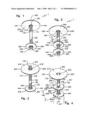
[0009]FIGS. 3 and 4 illustrate, in addition to the elements seen in FIGS. 1 and 2, is at least one n-stabilizing disk (400) having a n-stabilizing disk top side (410) and a n-stabilizing disk bottom side (420); seen is n-stabilizing disk-rod affixing means (430). Also illustrated is the n-stabilizing disk spacing (460) between the stabilizing disk bottom (320) and the at least one n-stabilizing disk top (410).
[0010]FIG. 5 illustrates the rod (100), rod threads (130), a stabilizing disk (300) showing a stabilizing disk-bevel (335) and a n-stabilizing disk (400) showing a n-stabilizing disk-bevel (435). Also seen is the n-stabilizing disk spacing (460) illustrated as a 0.0'' space.
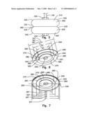
[0011]FIGS. 6 and 7 are illustrations of a valve housing or box lid (200). FIG. 6 shows a lid first sealing ring (260) having a first sealing ring major diameter (265) and a first sealing ring major diameter length D2 (267); seen is a lid second sealing ring (280) having a second sealing ring major diameter (285) with a second sealing ring major diameter length D3 (287); also illustrated is a lid annulus (270) between the lid first sealing ring (260) and the lid second sealing ring (280). FIG. 7 additionally illustrates a lid sealing ring (290) having a lid sealing ring major diameter (295) and a lid sealing ring major diameter length D6 (297). Seen in FIG. 7 is both the lid annulus (270) and lid first annulus (275).
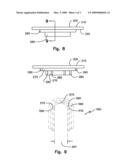
[0012]FIGS. 8 and 9 illustrate an elevation of the valve housing or box lid (200) of FIG. 6 showing the lid first sealing ring (260) and the lid second sealing ring (280). FIG. 9 is section 9 from FIG. 8 showing the lid annulus (270). FIG. 9 also illustrates, in phantom, an upstanding valve housing (500) showing a water valve housing first annulus (590), a water valve housing first sealing pipe (575), a water valve housing second sealing pipe (570), a water valve housing n-sealing pipe (580) and a water valve housing second annulus (560).
DETAILED DESCRIPTION
[0013]FIGS. 1, 2, 3 and 4 illustrate a lid stabilizing apparatus (1). The apparatus comprises at least one elongated rod (100) having a first end (110) and a second end (120). The at least one elongated rod (100) generally rigid and composed of metals, plastics, composite materials including carbon fiber materials or other rigid materials. A lid (200) has a top side (210) and a bottom side (220) and a lid aperture (250), centrally positioned from the top side (210) to the bottom side (220). The at least one elongated rod (100) is received at the first end (110) by the lid aperture (250) at the bottom side (220) and affixed to the lid (200) by lid-rod affixing means (230) to immovably interconnect the lid (200) and the rod (100). Received, as used herein, means that an element of the invention is sized to have another element pass through or fit into or, that an element is sized to pass through or fit into another element of the invention. The lid (200) has a major diameter (240) and is generally circular. The lid (200) is generally planar and formed of rigid materials including metals, plastics, composite materials, carbon fiber materials or other rigid materials.
[0014]A lid sealing ring (290), seen in FIG. 7, 8 and 9, has a lid sealing ring major diameter (295), is generally circular and downwardly extends from the lid bottom side (220). The lid sealing ring (290) is centrally positioned relative to the lid aperture (250). The lid sealing ring major diameter (295) is aligned with the lid major diameter (240) and has a lid sealing ring major diameter length D6 (297) which is less than the lid major diameter length D1 (247).
[0015]A lid first sealing ring (260), illustrated in FIG. 6, 7, 8 and 9, having a first sealing ring major diameter (265) is generally circular and downwardly extends from the lid bottom side (220). The lid first sealing ring (260) is centrally positioned relative to the lid aperture (250). The first sealing ring major diameter (265) aligned with the lid major diameter (240) and the lid first sealing ring major diameter (260) has a first sealing ring major diameter length D2 (267) which is less than the lid sealing ring major diameter length D6 (297).
[0016]A lid second sealing ring (280), seen in FIG. 6, 7, 8 and 9, has a second sealing ring major diameter (285) is generally circular and downwardly extends from the lid bottom side (220). The lid second sealing ring (280) centrally positioned relative to the lid aperture (250). The second sealing ring major diameter (285) aligned with the lid major diameter (240) and the second sealing ring major diameter (285) has a second sealing ring major diameter length D3 (287) which is less than the first sealing ring major diameter length D2 (267). A lid first annulus (275) is formed between the lid sealing ring (290) and the lid first sealing ring (260). A lid annulus (270) is formed between the lid first sealing ring (260) and the lid second sealing ring (280). The lid sealing ring (290), lid first sealing ring (260) and lid second sealing ring (280) are generally formed from a machining, molding or casting process from metals, plastics, carbon fiber materials or other rigid materials.
[0017]An at least one stabilizing disk (300), shown in FIG. 1 through 5, has a stabilizing disk top side (310) and a stabilizing disk bottom side (320) and a stabilizing disk aperture (350) centrally positioned from the stabilizing disk top side (310) to the stabilizing disk bottom side (320). The at lest one elongated rod (100) received at the second end (120) by the stabilizing disk aperture (350) at the top side (320) and affixed to the at least one stabilizing disk (300) by stabilizing disk-rod affixing means (330) to immovably interconnect the at least one stabilizing disk (300) and the rod (100). The at least one stabilizing disk (300), at the top side (310) and or the bottom side (320), is beveled as seen in FIG. 5, with a stabilizing disk-bevel (335) most distal from the stabilizing disk aperture (350). The at least one stabilizing disk (300) has a stabilizing disk major diameter (340) and is generally circular. The stabilizing disk major diameter (340) has a stabilizing disk major diameter length D4 (347) which is less than the lid major diameter length D1 (247) and generally less than the first sealing ring major diameter length D2 (347). The n-stabilizing disk major diameter (440) has a n-stabilizing disk major diameter length D5 (447) which is less than the lid major diameter length D1 (247) and generally equal to the first sealing ring major diameter length D2 (347).
[0018]The at least one elongated rod (100), found in FIGS. 1 through 5, extends outwardly from the lid bottom side (210) and is affixed at the second end (120) to at least one stabilizing disk top side (310). The at least one elongated rod (100) is generally orthogonal to the lid (200) and generally orthogonal to the at least one stabilizing disk (300);
[0019]A lid-rod affixing means (230), shown in FIGS. 1 through 5, immovably affixes the lid (200) and the rod (100). The lid-rod affixing means (230) is generally centrally positioned relative to the lid top side (210) and the lid bottom side (220). The lid-rod affixing means (230) includes a centrally positioned lid aperture (250) from the top side (210) to the bottom side (220) where the lid aperture (250) may be threaded to receive the rod (100) having threads (130). The rod (100) at the first end (110) is sized to pass through the lid aperture (250) to be secured by a lid nut (230) at the lid top side (210) and a lid nut (230) at the lid bottom side (220). Alternatively the elongated rod (100) may be welded, glued or other affixed by immovable affixing means to the lid (200) to prevent movement between the rod (100) and the lid (200).
[0020]At least one n-stabilizing disk (400), shown in FIG. 3, 4 and 5, has a n-stabilizing disk top side (410) and a n-stabilizing disk bottom side (420). The n-stabilizing disk (400) has a n-stabilizing disk major diameter (440) which has a n-stabilizing disk major diameter length D5 (447) which is generally equal to the length of the stabilizing disk major diameter length D4 (347). A n-stabilizing disk aperture (450) from the n-stabilizing disk top side (410) to the n-stabilizing disk bottom side (420). There is a n-stabilizing disk spacing (460) between the stabilizing disk bottom (320) and the n-stabilizing disk top (410). A n-stabilizing disk-rod affixing means (430) immovably affixes the n-stabilizing disk (400) and the rod (100) which may be by a nut (430) received by rod threads (130) at the n-stabilizing disk top side (410) and a nut (430) received by rod threads (130) at the n-stabilizing disk bottom side (420). The at least one stabilizing disk (300) and the at least one n-stabilizing disk (400) are generally planar and circular and formed from rigid materials including metals, plastics, carbon fiber materials and other rigid and alternatively formed from semi-rigid materials including rubber impregnated cork and poly-foams such as polyethylene. It will be understood that "n", relative to the n-stabilizing disk (400), denotes the existence of a number of disks to be determined by the application.
[0021]In the preferred embodiment the Lid Stabilizing Apparatus (1) is applied to restraining the lids (200) valve boxes (500) including municipal water valve boxes or housings (500), illustrated in FIG. 9, from being dislodged and, as an example, tossed into the street. The preferred embodiment, for the at least one stabilizing disk (300) and the at least one n-stabilizing disk (400), will employ materials which will provide a friction or near friction engagement with the valve box (500) while not tending to become lodged within the valve box (500). The materials where the application is a valve box (500) will tend to be with semi-rigid materials such as rubber impregnated cork and dense poly-foams. It is recognized that other applications will likely employ rigid materials including metals.
[0022]The stabilizing disk may have a stabilizing disk bevel (335), shown at FIG. 5, at the stabilizing disk top (310) and or stabilizing disk bottom (350) and the at least one n-stabilizing disk may have a stabilizing disk bevel (435) at the n-stabilizing disk top (410) and or n-stabilizing disk bottom (420) distal from the n-stabilizing disk aperture (450). The stabilizing disk bevel (335) functions to lessen the difficulty in extracting the Lid Stabilizing Apparatus (1) from a valve box (500) in order to gain access to a valve, including a water valve, a gas valve or other structure.
[0023]The lid (200) at the lid bottom side (220) is sized to cover a valve box or housing (500). A valve box (500) may be an upstanding pipe which will be covered by the lid (200). In yet other versions of a valve box (500) there may be one or more concentric pipes presenting alternating pipe with annulus which is to receive the lid (200). Such is illustrated in FIG. 9 where a lid (200) is shows relative to a phantom illustrated valve box (500) which The lid sealing ring (290) is received into a valve housing first annulus (590); the lid first annulus (275) receiving a valve housing first sealing pipe (575); lid first sealing ring (260) received into a valve housing second annulus (560); lid annulus (270) receiving a valve housing second sealing pipe (570); lid second sealing ring (280) received into a valve housing n-sealing pipe (580).
Claims:
1. A lid stabilizing apparatus (1) comprising:a. at least one elongated
rod (100) having a first end (110) and a second end (120); the at least
one elongated rod (100) generally rigid and composed of metals, plastics,
carbon fiber materials or other rigid materials;b. a lid (200) having a
top side (210) and a bottom side (220); a lid aperture (250), centrally
positioned from the top side (210) to the bottom side (220); the at lest
one elongated rod (100) received at the first end (110) by the lid
aperture (250) at the top side (210) or the bottom side (220) and affixed
to the lid (200) by lid-rod affixing means (230) to immovably
interconnect the lid (200) and the rod (100); the lid (200) has a major
diameter (240) and is generally circular; the lid (200) generally planar
and formed of rigid materials including metals, plastics, carbon fiber
materials or other rigid materials;c. a lid sealing ring (290) having a
lid sealing ring major diameter (295) is generally circular and
downwardly extends from the lid bottom side (220); the lid sealing ring
(290) is centrally positioned relative to the lid aperture (250); the lid
sealing ring major diameter (295) is aligned with the lid major diameter
(240) and has a lid sealing ring major diameter length D6 (297) which is
less than the lid major diameter length D1 (247);d. a lid first sealing
ring (260) having a first sealing ring major diameter (265) is generally
circular and downwardly extends from the lid bottom side (220); the lid
first sealing ring (260) centrally positioned relative to the lid
aperture (250); the first sealing ring major diameter (265) aligned with
the lid major diameter (240); the lid first sealing ring major diameter
(260) has a first sealing ring major diameter length D2 (267) which is
less than the lid sealing ring major diameter length D6 (297);e. a lid
second sealing ring (280) having a second sealing ring major diameter
(285) is generally circular and downwardly extends from the lid bottom
side (220); the lid second sealing ring (280) centrally positioned
relative to the lid aperture (250); the second sealing ring major
diameter (285) aligned with the lid major diameter (240); the second
sealing ring major diameter (285) has a second sealing ring major
diameter length D3 (287) which is less than the first sealing ring major
diameter length D2 (267);f. a lid first annulus (275) is formed between
the lid sealing ring (290) and the lid first sealing ring (260); a lid
annulus (270) is formed between the lid first sealing ring (260) and the
lid second sealing ring (280); lid sealing ring (290), lid first sealing
ring (260) and lid second sealing ring (280) are generally formed from a
machining, molding or casting process from metals, plastics, carbon fiber
materials or other rigid materials;g. at least one stabilizing disk (300)
having a stabilizing disk top side (310) and a stabilizing disk bottom
side (320); a stabilizing disk aperture (350) centrally positioned from
the stabilizing disk top side (310) to the stabilizing disk bottom side
(320); the at lest one elongated rod (100) received at the second end
(120) by the stabilizing disk aperture (350) at the top side (320) and
immovably affixed to the at least one stabilizing disk (300) by
stabilizing disk-rod affixing means (330); the at least one stabilizing
disk (300), at the bottom side (320), is beveled, with a stabilizing
disk-bevel (335) most distal from the stabilizing disk aperture (350);
the at least one stabilizing disk (300) has a stabilizing disk major
diameter (340) and is generally circular; the stabilizing disk major
diameter (340) has a stabilizing disk major diameter length D4 (347)
which is less than the lid major diameter length D1 (247) and generally
less than the first sealing ring major diameter length D2 (347);h. at
least one n-stabilizing disk (400) having a n-stabilizing disk top side
(410) and a n-stabilizing disk bottom side (420); the n-stabilizing disk
(400) having a n-stabilizing disk major diameter(440) which has a
n-stabilizing disk major diameter length D5 (447) which is generally
equal to the length of the stabilizing disk major diameter length D4
(347); a n-stabilizing disk aperture (450) from the n-stabilizing disk
top side (410) to the n-stabilizing disk bottom side (420); n-stabilizing
disk spacing (460) between the stabilizing disk bottom (320) and the
n-stabilizing disk top (410); n-stabilizing disk-rod affixing means (430)
immovably affixing the n-stabilizing disk (400) and the rod (100) may be
by a nut (430) received by rod threads (130) at the n-stabilizing disk
top side (410) and a nut (430) received by rod threads (130) at the
n-stabilizing disk bottom side (420); the at least one stabilizing disk
(300) and the at least one n-stabilizing disk (400) generally planar and
formed from rigid materials including metals, plastics, carbon fiber
materials and other rigid and semi-rigid materials including rubber
impregnated cork and poly-foams such as polyurethane;I. the at least one
elongated rod (100) extending outwardly from the lid bottom side (220)
and immovably affixed, by lid-rod affixing means, at or proximal to the
second end (120) to the at least one stabilizing disk (300); the at least
one elongated rod (100) generally orthogonal to the lid (200) and
generally orthogonal to the at least one stabilizing disk (300);j. the
lid (200) having a lid-rod affixing means (230) to immovably affix the
lid (200) and the rod (100); the lid-rod affixing means (230) generally
centrally positioned relative to the lid top side (210) and the lid
bottom side (220); the lid-rod affixing means (230) including a centrally
positioned lid aperture (250) from the top side (210) to the bottom side
(220); the lid aperture (250) may be threaded to receive the rod (100)
having threads (130); the rod (100) at the first end (110) sized to pass
through the lid aperture (250) to be secured by a lid nut (230) at the
lid top side (210) and a lid nut (230) at the lid bottom side (220);
alternatively the elongated rod (100) may be welded, glued or other
affixed by immovable affixing means to the lid (200) to prevent movement
between the rod (100) and the lid (200),k. the at least one stabilizing
disk having a stabilizing disk bevel (335) at the stabilizing disk top
(310) and or stabilizing disk bottom (320) distal from the stabilizing
disk aperture (350); the at least one n-stabilizing disk having a
stabilizing disk bevel (435) at the n-stabilizing disk top (410) and or
n-stabilizing disk bottom (420) distal from the n-stabilizing disk
aperture (450);l. the lid (200) at the lid bottom side (220) sized to
cover a valve housing (500).
2. A lid stabilizing apparatus (1) comprising:a. at least one elongated rod (100) having a first end (110) and a second end (120);b. a lid (200) having a top side (210), a bottom side (220); the at least one elongated rod (100) is immovably affixed centrally to the lid (200), by lid-rod affixing means (230), at the lid bottom (220); the lid (200) is generally circular and has a major diameter (240); the rod (100) extends outwardly from the bottom side (220);c. an at least one stabilizing disk (300) has a stabilizing disk top side (310) and a stabilizing disk bottom side (320); the at least one elongated rod (100) is immovably affixed at or proximal to the second end (120) to the stabilizing disk (300) at the top side (310) and or at the top side (310) and the bottom side (320) by stabilizing disk-rod affixing means (330); the at least one stabilizing disk (300) is distal to the lid (200); the at least one stabilizing disk (300) has a stabilizing disk major diameter (340) and is generally circular; the stabilizing disk major diameter (340) has a stabilizing disk major diameter length D4 (347) which is less than the a lid major diameter length D1 (247).
3. The apparatus of claim 2 further comprising:a. a lid aperture (250), centrally positioned from the top side (210) to the bottom side (220); the at lest one elongated rod (100) received at the first end (110) by the lid aperture (250) at the top side (210) or the bottom side (220) and affixed to the lid (200) by lid-rod affixing means (230) to immovably interconnect the lid (200) and the rod (100); the at least one elongated rod (100) is generally rigid and composed of metals, plastics, composites or other rigid materials;b. the lid (200) is generally planar and formed of rigid materials including metals, plastics, carbon fiber materials or other rigid materials;c. the stabilizing disk (300) has a stabilizing disk aperture (350) centrally positioned from the stabilizing disk top side (310) to the stabilizing disk bottom side (320); the rod (100) is received at the second end (120) by the stabilizing disk aperture (350) at the stabilizing disk top side (310) and or bottom side (320);d. at least one n-stabilizing disk (400) has a n-stabilizing disk top side (410) and a n-stabilizing disk bottom side (420); the at lest one elongated rod (100), extending outwardly from the at least one stabilizing disk bottom (320), is immovably affixed by n-stabilizing disk-rod affixing means (430) at or proximal to the second end (120) to the n-stabilizing disk (400) at the top side (420);e. the n-stabilizing disk (400) has a n-stabilizing disk major diameter(440) which has a n-stabilizing disk major diameter length D5 (447) which is generally equal to the length of the stabilizing disk major diameter length D4 (347).f. the lid (200) at the lid bottom side (220) and lid major diameter length D1 (247) is sized to cover a valve box or housing (500); the stabilizing disk (300) and at least one n-stabilizing disk (400) are sized to be received into a valve box (500).
4. The apparatus of claim 3 further comprising:a. the at least one elongated rod (100) is generally orthogonal to the lid (200) and generally orthogonal to the at least one stabilizing disk (300) and to the at least one n-stabilizing disk (400);b. the lid aperture (250) may be threaded to receive the rod (100) having threads (130); the rod (100) at the first end (110) is sized to pass through the lid aperture (250) to be secured by lid-rod affixing means (230) including by a lid nut (230) at the lid top side (210) and a lid nut (230) at the lid bottom side (220); alternatively the elongated rod (100) may be welded, glued or other affixed by immovable affixing means to the lid (200) to prevent movement between the rod (100) and the lid (200);c. the at least one stabilizing disk (300), at the top side (310) and or the bottom side (320), is beveled with a stabilizing disk-bevel (335) most distal from the stabilizing disk aperture (350); the at least one stabilizing disk (300) has a stabilizing disk major diameter (340) and is generally circular; the stabilizing disk major diameter (340) has a stabilizing disk major diameter length D4 (347) which is less than the lid major diameter length D1 (247) and generally less than the first sealing ring major diameter length D2 (347);d. the at lest one elongated rod (100), extending outwardly from the at least one stabilizing disk bottom (320), is received by an n-stabilizing disk aperture (450) and immovably affixed by n-stabilizing disk affixing means (430) at or proximal to the second end (120) at the n-stabilizing disk top side (420); a n-stabilizing disk spacing (460) between the stabilizing disk bottom (320) and the n-stabilizing disk top (410);e. the at least one stabilizing disk (300) and the at least one n-stabilizing disk (400) are generally planar and circular and formed from rigid materials including metals, plastics, carbon fiber materials and other rigid and alternatively formed from semi-rigid materials including rubber impregnated cork and poly-foams such as polyurethane;f. at least one lid sealing ring (290) having a lid sealing ring major diameter (295) downwardly extends from the lid bottom side (220); the lid sealing ring (290) is centrally positioned relative to the lid aperture (250); the lid sealing ring major diameter (295) is aligned with the lid major diameter (240) and has a lid sealing ring major diameter length D6 (297) which is less than the lid major diameter length D1 (247);g. the at least one stabilizing disk (300) and the at least one n-stabilizing disk (400) sized to provide a friction or near friction engagement with a valve box (500).
5. The apparatus of claim 4 further comprising:a. the n-stabilizing disk-rod affixing means (430) immovably affixes the n-stabilizing disk (400) and the rod (100) which may be by a nut (430) received by rod threads (130) at the n-stabilizing disk top side (410) and a nut (430) received by rod threads (130) at the n-stabilizing disk bottom side (420);b. the at least one n-stabilizing disk may have a stabilizing disk bevel (435) at the n-stabilizing disk top (410) and or n-stabilizing disk bottom (420) distal from the n-stabilizing disk aperture (450); the n-stabilizing disk bevel (435) functions to lessen the difficulty in extracting the Lid Stabilizing Apparatus (1) from a valve box (500) in order to gain access to a valve or other structure;c. the n-stabilizing disk spacing (460) between the stabilizing disk bottom (320) and the n-stabilizing disk top (410) is in the range of a distance equal to the major diameter of the valve box (567) to a distance of zero inches (0.0");d. a lid first sealing ring (260) having a first sealing ring major diameter (265) downwardly extends from the lid bottom side (220); the lid first sealing ring (260) is centrally positioned relative to the lid aperture (250); the first sealing ring major diameter (265) aligned with the lid major diameter (240) and the lid first sealing ring major diameter (260) has a first sealing ring major diameter length D2 (267) which is less than the lid sealing ring major diameter length D6 (297);e. a lid second sealing ring (280) has a second sealing ring major diameter and downwardly extends from the lid bottom side (220); the lid second sealing ring (280) centrally positioned relative to the lid aperture (250); the second sealing ring major diameter (285) aligned with the lid major diameter (240) and the second sealing ring major diameter (285) has a second sealing ring major diameter length D3 (287) which is less than the first sealing ring major diameter length D2 (267); a lid first annulus (275) is formed between the lid sealing ring (290) and the lid first sealing ring (260); a lid annulus (270) is formed between the lid first sealing ring (260) and the lid second sealing ring (280); the lid sealing ring (290), lid first sealing ring (260) and lid second sealing ring (280) are generally formed from a machining, molding or casting process from metals, plastics, carbon fiber materials or other rigid materials;f. the lid sealing ring (290), the lid first sealing ring (260) and the lid second sealing ring (280) are generally circular.
Description:
FIELD OF THE INVENTION
[0001]This invention relates to an apparatus which covers the open end of a tube, as a lid, and resists being dislodged. The invention more specifically relates to an apparatus which covers a tubular access enclosure providing access to structure including a valve. The invention relates to an apparatus covering the open end of a valve box including an underground valve housing.
BACKGROUND OF THE INVENTION
[0002]Municipal services include water and other services where pipe and valves, located beneath the surface of a street, are primary components of the service. Underground valve housings are covered with a cap or cover which is subject to vehicular traffic. Such traffic frequently dislodges valve housing covers allowing debris into the housing and causing damage to the housing and cover. Devices which relate to covering or enclosing underground tubular structures include U.S. Pat. No. 5,253,952 to Selway; U.S. Pat. No. 5,240,032 to Mizioch; U.S. Pat. No. 6,449,908 to Gagas; U.S. Pat. No. 6,036,401 to Morina et al. Devices which relate to structures otherwise having similarities to the invention herein include U.S. Pat. No. 22,535 to Willloughby; U.S. Pat. No. 6,488,440 to Hill; U.S. Pat. No. 4,101,154 to Kagstrom; U.S. Pat. No. 6,584,734 to Mihalicz et al; U.S. Pat. No. 5,403,116 to Brewer; U.S. Pat. No. 5,154,681 to Denny; and U.S. Pat. No. 5,607,379 to Scott.
[0003]The patents referred to herein are provided herewith in an Information Disclosure Statement in accordance with 37 CFR 1.97.
SUMMARY OF THE INVENTION
[0004]The lid stabilizing apparatus (1) comprises a rod (100) immovably interconnected with a lid (200) at a lid aperture (250). The rod (100) downwardly extends from the lid (200) and is immovably affixed to a stabilizing disk (300) at a stabilizing disk aperture (350); the rod may as well extend downwardly from the stabilizing disk (300) and there be received, by at least one n-stabilizing disks (400) at a n-stabilizing disk aperture (450) and there be immovably affixed to the at least one n-stabilizing disk (400).
[0005]The lid (200) has a lid major diameter (240) with a lid major diameter length D1 (247). The stabilizing disk (300) has a stabilizing disk major diameter (340) having a stabilizing disk major diameter length D4 (347) which is generally less in length then that of the lid major diameter length D1 (247). Additionally, there may be at least one n-stabilizing disks (400) having a n-stabilizing disk major diameter length D5 which is generally equal in length to that of the stabilizing disk major diameter length D4 (347).
[0006]The lid (200) may be formed at a water valve cover as found in municipal water systems generally in the middle of a street. The stabilizing disk (300) and possibly at least one n-stabilizing disk (400), extending downwardly from the lid (200) are generally of a diameter which will be either in a friction or near friction engagement with the valve pipe extending upwardly from a municipal water valve to the surface of a street. The stabilizing disk (300) and, where used, the at least one n-stabilizing disk (400) will resist forces tending to dislodge a water valve lid (200) or cover when struck by vehicular traffic.
BRIEF DESCRIPTION OF THE DRAWINGS
[0007]The foregoing and other features and advantages of the present invention will become more readily appreciated as the same become better understood by reference to the following detailed description of the preferred embodiment of the invention when taken in conjunction with the accompanying drawings, wherein:
[0008]FIGS. 1 and 2 illustrates a lid stabilizing apparatus (1) showing a rod (100), having a rod first end (110) and a rod second end (120) with rod threads (130); also seen is a lid (200) having a lid top side (210) and a sld bottom side (220); seen is lid-rod affixing means (230), a lid major diameter (240) having a lid major diameter length D1 (247) and a lid aperture (250); seen is a stabilizing disk (300) having a stabilizing disk top side (310) and a stabilizing disk bottom side (320); also illustrated is stabilizing disk-rod affixing means (330); seen is a stabilizing disk major diameter (340) having a stabilizing disk major diameter length D4 (347) and a stabilizing disk aperture (350).
[0009]FIGS. 3 and 4 illustrate, in addition to the elements seen in FIGS. 1 and 2, is at least one n-stabilizing disk (400) having a n-stabilizing disk top side (410) and a n-stabilizing disk bottom side (420); seen is n-stabilizing disk-rod affixing means (430). Also illustrated is the n-stabilizing disk spacing (460) between the stabilizing disk bottom (320) and the at least one n-stabilizing disk top (410).
[0010]FIG. 5 illustrates the rod (100), rod threads (130), a stabilizing disk (300) showing a stabilizing disk-bevel (335) and a n-stabilizing disk (400) showing a n-stabilizing disk-bevel (435). Also seen is the n-stabilizing disk spacing (460) illustrated as a 0.0'' space.
[0011]FIGS. 6 and 7 are illustrations of a valve housing or box lid (200). FIG. 6 shows a lid first sealing ring (260) having a first sealing ring major diameter (265) and a first sealing ring major diameter length D2 (267); seen is a lid second sealing ring (280) having a second sealing ring major diameter (285) with a second sealing ring major diameter length D3 (287); also illustrated is a lid annulus (270) between the lid first sealing ring (260) and the lid second sealing ring (280). FIG. 7 additionally illustrates a lid sealing ring (290) having a lid sealing ring major diameter (295) and a lid sealing ring major diameter length D6 (297). Seen in FIG. 7 is both the lid annulus (270) and lid first annulus (275).
[0012]FIGS. 8 and 9 illustrate an elevation of the valve housing or box lid (200) of FIG. 6 showing the lid first sealing ring (260) and the lid second sealing ring (280). FIG. 9 is section 9 from FIG. 8 showing the lid annulus (270). FIG. 9 also illustrates, in phantom, an upstanding valve housing (500) showing a water valve housing first annulus (590), a water valve housing first sealing pipe (575), a water valve housing second sealing pipe (570), a water valve housing n-sealing pipe (580) and a water valve housing second annulus (560).
DETAILED DESCRIPTION
[0013]FIGS. 1, 2, 3 and 4 illustrate a lid stabilizing apparatus (1). The apparatus comprises at least one elongated rod (100) having a first end (110) and a second end (120). The at least one elongated rod (100) generally rigid and composed of metals, plastics, composite materials including carbon fiber materials or other rigid materials. A lid (200) has a top side (210) and a bottom side (220) and a lid aperture (250), centrally positioned from the top side (210) to the bottom side (220). The at least one elongated rod (100) is received at the first end (110) by the lid aperture (250) at the bottom side (220) and affixed to the lid (200) by lid-rod affixing means (230) to immovably interconnect the lid (200) and the rod (100). Received, as used herein, means that an element of the invention is sized to have another element pass through or fit into or, that an element is sized to pass through or fit into another element of the invention. The lid (200) has a major diameter (240) and is generally circular. The lid (200) is generally planar and formed of rigid materials including metals, plastics, composite materials, carbon fiber materials or other rigid materials.
[0014]A lid sealing ring (290), seen in FIG. 7, 8 and 9, has a lid sealing ring major diameter (295), is generally circular and downwardly extends from the lid bottom side (220). The lid sealing ring (290) is centrally positioned relative to the lid aperture (250). The lid sealing ring major diameter (295) is aligned with the lid major diameter (240) and has a lid sealing ring major diameter length D6 (297) which is less than the lid major diameter length D1 (247).
[0015]A lid first sealing ring (260), illustrated in FIG. 6, 7, 8 and 9, having a first sealing ring major diameter (265) is generally circular and downwardly extends from the lid bottom side (220). The lid first sealing ring (260) is centrally positioned relative to the lid aperture (250). The first sealing ring major diameter (265) aligned with the lid major diameter (240) and the lid first sealing ring major diameter (260) has a first sealing ring major diameter length D2 (267) which is less than the lid sealing ring major diameter length D6 (297).
[0016]A lid second sealing ring (280), seen in FIG. 6, 7, 8 and 9, has a second sealing ring major diameter (285) is generally circular and downwardly extends from the lid bottom side (220). The lid second sealing ring (280) centrally positioned relative to the lid aperture (250). The second sealing ring major diameter (285) aligned with the lid major diameter (240) and the second sealing ring major diameter (285) has a second sealing ring major diameter length D3 (287) which is less than the first sealing ring major diameter length D2 (267). A lid first annulus (275) is formed between the lid sealing ring (290) and the lid first sealing ring (260). A lid annulus (270) is formed between the lid first sealing ring (260) and the lid second sealing ring (280). The lid sealing ring (290), lid first sealing ring (260) and lid second sealing ring (280) are generally formed from a machining, molding or casting process from metals, plastics, carbon fiber materials or other rigid materials.
[0017]An at least one stabilizing disk (300), shown in FIG. 1 through 5, has a stabilizing disk top side (310) and a stabilizing disk bottom side (320) and a stabilizing disk aperture (350) centrally positioned from the stabilizing disk top side (310) to the stabilizing disk bottom side (320). The at lest one elongated rod (100) received at the second end (120) by the stabilizing disk aperture (350) at the top side (320) and affixed to the at least one stabilizing disk (300) by stabilizing disk-rod affixing means (330) to immovably interconnect the at least one stabilizing disk (300) and the rod (100). The at least one stabilizing disk (300), at the top side (310) and or the bottom side (320), is beveled as seen in FIG. 5, with a stabilizing disk-bevel (335) most distal from the stabilizing disk aperture (350). The at least one stabilizing disk (300) has a stabilizing disk major diameter (340) and is generally circular. The stabilizing disk major diameter (340) has a stabilizing disk major diameter length D4 (347) which is less than the lid major diameter length D1 (247) and generally less than the first sealing ring major diameter length D2 (347). The n-stabilizing disk major diameter (440) has a n-stabilizing disk major diameter length D5 (447) which is less than the lid major diameter length D1 (247) and generally equal to the first sealing ring major diameter length D2 (347).
[0018]The at least one elongated rod (100), found in FIGS. 1 through 5, extends outwardly from the lid bottom side (210) and is affixed at the second end (120) to at least one stabilizing disk top side (310). The at least one elongated rod (100) is generally orthogonal to the lid (200) and generally orthogonal to the at least one stabilizing disk (300);
[0019]A lid-rod affixing means (230), shown in FIGS. 1 through 5, immovably affixes the lid (200) and the rod (100). The lid-rod affixing means (230) is generally centrally positioned relative to the lid top side (210) and the lid bottom side (220). The lid-rod affixing means (230) includes a centrally positioned lid aperture (250) from the top side (210) to the bottom side (220) where the lid aperture (250) may be threaded to receive the rod (100) having threads (130). The rod (100) at the first end (110) is sized to pass through the lid aperture (250) to be secured by a lid nut (230) at the lid top side (210) and a lid nut (230) at the lid bottom side (220). Alternatively the elongated rod (100) may be welded, glued or other affixed by immovable affixing means to the lid (200) to prevent movement between the rod (100) and the lid (200).
[0020]At least one n-stabilizing disk (400), shown in FIG. 3, 4 and 5, has a n-stabilizing disk top side (410) and a n-stabilizing disk bottom side (420). The n-stabilizing disk (400) has a n-stabilizing disk major diameter (440) which has a n-stabilizing disk major diameter length D5 (447) which is generally equal to the length of the stabilizing disk major diameter length D4 (347). A n-stabilizing disk aperture (450) from the n-stabilizing disk top side (410) to the n-stabilizing disk bottom side (420). There is a n-stabilizing disk spacing (460) between the stabilizing disk bottom (320) and the n-stabilizing disk top (410). A n-stabilizing disk-rod affixing means (430) immovably affixes the n-stabilizing disk (400) and the rod (100) which may be by a nut (430) received by rod threads (130) at the n-stabilizing disk top side (410) and a nut (430) received by rod threads (130) at the n-stabilizing disk bottom side (420). The at least one stabilizing disk (300) and the at least one n-stabilizing disk (400) are generally planar and circular and formed from rigid materials including metals, plastics, carbon fiber materials and other rigid and alternatively formed from semi-rigid materials including rubber impregnated cork and poly-foams such as polyethylene. It will be understood that "n", relative to the n-stabilizing disk (400), denotes the existence of a number of disks to be determined by the application.
[0021]In the preferred embodiment the Lid Stabilizing Apparatus (1) is applied to restraining the lids (200) valve boxes (500) including municipal water valve boxes or housings (500), illustrated in FIG. 9, from being dislodged and, as an example, tossed into the street. The preferred embodiment, for the at least one stabilizing disk (300) and the at least one n-stabilizing disk (400), will employ materials which will provide a friction or near friction engagement with the valve box (500) while not tending to become lodged within the valve box (500). The materials where the application is a valve box (500) will tend to be with semi-rigid materials such as rubber impregnated cork and dense poly-foams. It is recognized that other applications will likely employ rigid materials including metals.
[0022]The stabilizing disk may have a stabilizing disk bevel (335), shown at FIG. 5, at the stabilizing disk top (310) and or stabilizing disk bottom (350) and the at least one n-stabilizing disk may have a stabilizing disk bevel (435) at the n-stabilizing disk top (410) and or n-stabilizing disk bottom (420) distal from the n-stabilizing disk aperture (450). The stabilizing disk bevel (335) functions to lessen the difficulty in extracting the Lid Stabilizing Apparatus (1) from a valve box (500) in order to gain access to a valve, including a water valve, a gas valve or other structure.
[0023]The lid (200) at the lid bottom side (220) is sized to cover a valve box or housing (500). A valve box (500) may be an upstanding pipe which will be covered by the lid (200). In yet other versions of a valve box (500) there may be one or more concentric pipes presenting alternating pipe with annulus which is to receive the lid (200). Such is illustrated in FIG. 9 where a lid (200) is shows relative to a phantom illustrated valve box (500) which The lid sealing ring (290) is received into a valve housing first annulus (590); the lid first annulus (275) receiving a valve housing first sealing pipe (575); lid first sealing ring (260) received into a valve housing second annulus (560); lid annulus (270) receiving a valve housing second sealing pipe (570); lid second sealing ring (280) received into a valve housing n-sealing pipe (580).
User Contributions:
Comment about this patent or add new information about this topic:
| People who visited this patent also read: | |
| Patent application number | Title |
|---|---|
| 20210329577 | DATA TRANSMISSION METHOD AND APPARATUS |
| 20210329576 | Information Indication Apparatus and Method and Communication System |
| 20210329575 | TRANSMISSION CONFIGURATION METHOD AND DEVICE |
| 20210329574 | SELECTION OF INITIAL ACQUISITION PARAMETERS FOR REDUCED-CAPABILITY DEVICES |
| 20210329573 | PRECISE TIME SYNCHRONIZATION FOR 4G AUTOMATIC LINK ESTABLISHMENT (ALE) STATIONS |
Images included with this patent application:
 |  |
 |  |
| Similar patent applications: | |
| Date | Title |
|---|---|
| 2010-10-28 | Composition and method for stabilizing road base |
| 2009-09-24 | System and method for stabilizing parking curb anchors |
| 2010-01-07 | Anti-terror car-attack defending apparatus |
| 2008-08-28 | Slot cutting apparatus |
| 2009-02-26 | Asphalt recycling apparatus |
| New patent applications in this class: | |
| Date | Title |
|---|---|
| 2019-05-16 | Manhole comprising a device for safety closing and locking the manhole |
| 2016-06-16 | Safe maintenance industrial covers |
| 2016-04-21 | Method and device for installing or renovating a basin |
| 2016-02-25 | Pressure responsive locking latch arrangement for manhole covers |
| 2016-02-25 | Controlled pressure release manhole cover assembly |
| Top Inventors for class "Road structure, process, or apparatus" | |
| Rank | Inventor's name |
|---|---|
| 1 | Günter Hähn |
| 2 | Martin Buschmann |
| 3 | Cyrus Barimani |
| 4 | Ralf Weiser |
| 5 | Ronald D. Shaw |