Patent application title: ANTENNA SHARING DEVICE
Inventors:
Tetsuya Tsurunari (Osaka, JP)
Katsuya Fujii (Hyogo, JP)
IPC8 Class: AH03H972FI
USPC Class:
333133
Class name: Having branched circuits for providing frequency separation utilizing electromechanical transducer
Publication date: 2009-03-05
Patent application number: 20090058557
des a piezoelectric substrate having a surface, a
grounding terminal to be grounded, first and second surface acoustic wave
(SAW) filters mounted on the piezoelectric substrate, first and second
terminals connected to the first and second SAW filters, respectively,
and a line mounted on the surface of the piezoelectric substrate between
the first SAW filter and the second SAW filter. A stray coupling path is
produced between the first and second terminals. A first end of the line
is connected to the grounding terminal. A second end of the line opens
and is coupled capacitively to the stray coupling path. The antenna
duplexer has large isolation characteristic between the surface acoustic
wave filters.Claims:
1. An antenna duplexer comprising:a piezoelectric substrate having a
surface thereof;a grounding terminal to be grounded;a first surface
acoustic wave (SAW) filter mounted on the surface of the piezoelectric
substrate;a second SAW filter mounted on the surface of the piezoelectric
substrate;a first terminal connected to the first SAW filter;a second
terminal connected to the second SAW filter, the second terminal
producing a stray coupling path between the first terminal and the second
terminal; anda line mounted on the surface of the piezoelectric substrate
between the first SAW filter and the second SAW filter, the line having a
first end and a second end, the first end of the line being connected to
the grounding terminal, the second end of the line opening and being
coupled capacitively to the stray coupling path.
2. The antenna duplexer according to claim 1, further comprising a package accommodating the piezoelectric substrate.Description:
TECHNICAL FIELD
[0001]The present invention relates to an antenna duplexer used in a communication apparatus.
BACKGROUND ART
[0002]A conventional antenna duplexer is disclosed in Japanese Patent Laid-Open Publication No. 2002-330057 includes surface acoustic wave filters different from each other. Each of the filters includes comb-shaped electrodes provided on a single piezoelectric substrate.
[0003]Such a conventional antenna duplexer requires isolation between the surface acoustic wave filters for allowing the surface acoustic wave filters to exert their characteristics effectively. To meet this requirement, the arrangement of these filters on the piezoelectric substrate is optimized, and a groove is provided in the substrate between a transmitting filter and a receiving filter so as to increase the isolation between the filters.
[0004]In the conventional antenna duplexer, the filters may be coupled with each other due to a surface acoustic wave coupling for coupling the filters by surface acoustic waves on the piezoelectric substrate and to a high-frequency coupling form coupling the filters by a transmitting signal and a received signal interfere with each other. The groove provided in the substrate cannot suppress the high-frequency coupling, hence not improving the isolation between the surface acoustic wave filters.
SUMMARY OF THE INVENTION
[0005]An antenna duplexer includes a piezoelectric substrate having a surface, a grounding terminal to be grounded, first and second surface acoustic wave (SAW) filters mounted on the piezoelectric substrate, first and second terminals connected to the first and second SAW filters, respectively, and a line mounted on the surface of the piezoelectric substrate between the first SAW filter and the second SAW filter. A stray coupling path is produced between the first and second terminals. A first end of the line is connected to the grounding terminal. A second end of the line opens and is coupled capacitively to the stray coupling path.
[0006]The antenna duplexer has large isolation characteristic between the surface acoustic wave filters.
BRIEF DESCRIPTION OF THE DRAWINGS
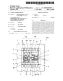
[0007]FIG. 1 is a top view of an antenna duplexer according to an exemplary embodiment of the present invention.
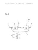
[0008]FIG. 2 is an equivalent circuit diagram of the antenna duplexer according to the embodiment.
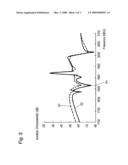
[0009]FIG. 3 illustrates isolation characteristics of the antenna duplexer according to the embodiment
REFERENCE NUMERALS
[0010]1 Package [0011]2 Piezoelectric Substrate [0012]2A Surface of Piezoelectric Substrate [0013]4 Receiving SAW Filter (Second SAW Filter) [0014]Transmitting SAW Filter (First SAW Filter) [0015]7 Transmitting Terminal (First Terminal) [0016]8 Receiving Terminal (Second Terminal) [0017]9 Antenna Terminal [0018]12 Shielding Line [0019]12A End of Shielding Line (First End) [0020]12B End of Shielding Line (Second End) [0021]13 Stray Coupling Path [0022]14 Coupling Capacitor
DETAIL DESCRIPTION OF THE PREFERRED EMBODIMENT
[0023]FIG. 1 is a top view of an antenna duplexer 1001 for use in a high-frequency module of a communications apparatus, such as a mobile telephone, to separate a transmitting signal and a received signal from each other, according to an exemplary embodiment of the present invention. The antenna duplexer 1001 includes a package 1 made of ceramic board and a piezoelectric substrate 2 accommodated in the package 1. The piezoelectric substrate 2 provides surface acoustic wave (SAW) filters. A receiving SAW filter 4 and a transmitting SAW filter 5 including transducers 3 including comb-shaped electrodes are mounted on a surface 2A of the piezoelectric substrate 2. The transducers 3 are connected with a wiring pattern 6.
[0024]A transmitting terminal 7, a receiving terminal 8, an antenna terminal 9, and grounding terminals 10 and 10A are provided at the package 1. The transmitting terminal 7 and the receiving terminal 8 are connected to the transmitting SAW filter 5 and the receiving SAW filter 4, respectively. These terminals are connected with the transmitting SAW filter 5 and the receiving SAW filter 4 via bonding wires 11.
[0025]The surface 2A of the piezoelectric substrate 2 has a region 105 thereof having the transmitting SAW filter 5 mounted thereon and a region 104 having the receiving SAW filter 4 mounted thereon. The transmitting SAW filter 5 and the receiving SAW filter 4 are coupled to each other by a high-frequency coupling which causes a transmitting signal and a received signal to interfere with each other. A shielding line 12 is provided on the surface 2A of the piezoelectric substrate between the regions 104 and 105 for suppressing the high-frequency coupling between the SAW filters 4 and 5
[0026]The shielding line 12 has ends 12A and 12B. The end 12A is connected via the bonding wire 11 to the grounding terminal 10A. The grounding terminal 10A is to be grounded. The end 12B opens as an open end. Being grounded, the shielding line 12 electro-magnetically isolates between the SAW filters 4 and 5.
[0027]FIG. 2 is an equivalent circuit diagram of the antenna duplexer 1001. The transmitting SAW filter 5 is connected between the antenna terminal 9 and the transmitting terminal 7. The receiving SAW filter 4 is connected between the antenna terminal 9 and the receiving terminal 8. A stray coupling path 13 may be produced due to parasitic capacitance coupling between the transmitting terminal 7 and the receiving terminal 9. The end 12B of the shielding line 12 is coupled capacitively to the stray coupling path 13 via a coupling capacitor 14 derived from a parasitic capacitance. More specifically, the coupling capacitor 14 is produced by the end 12A of the shielding line 12 and the wiring patterns 6A and 6B which are separated from each other but situated close to the end 12B.
[0028]The transmitting SAW filter 5 and the receiving SAW filter 4 determine passing characteristics of the antenna duplexer 1001 during a transmitting and a receiving, respectively. In addition, the shielding line 12 having the end 12A connected to the grounding terminal 10A functions as an inductor at high frequencies. The inductor is connected at the end 12B of the shielding line 12 in series to the coupling capacitor 14, thus providing a series resonance circuit 51. The stray coupling path 13 between the transmitting terminal 7 and the receiving terminal 8 is grounded via the series resonance circuit 51, and produces an attenuation pole for isolation between the transmitting terminal 7 and the receiving terminal 8, thereby improving the isolation.
[0029]FIG. 3 illustrates isolation characteristics between the transmitting terminal 7 and the receiving terminal 8. The vertical axis represents the isolation, and the horizontal axis represents frequencies. While the profile S1 denoted by the broken line represents the isolation characteristic between a receiving terminal and a transmitting terminal of a comparative antenna duplexer which does not include the shielding line 12, the profile S2 denoted by the solid line represents the isolation characteristic between the transmitting terminal 7 and the receiving terminal 8 of the antenna duplexer 1001 according to this embodiment. The profile S2 includes an attenuation pole P1 produced by the series resonance circuit 51 formed by the shielding line 12 and the coupling capacitor 14, and thus, an isolation characteristic better than that of the profile S1.
[0030]The transducers 3 mounted on the piezoelectric substrate 2 are coupled to each other by surface acoustic waves, that is, connected to each other by an acoustic coupling. The series resonance circuit 51 formed by the shielding line 12 and the coupling capacitor 14 influences only the high-frequency coupling between the transmitting terminal 7 and the receiving terminal 8, and does not influence the acoustic coupling of the transducers 3 between the transmitting terminal 7 and the antenna terminal 9 or between the antenna terminal 9 and the receiving terminal 8.
[0031]The series resonance circuit 51 is produced by a series resonance between an inductance of the shielding line 12 and the coupling capacitor 14 at the end 12B opening. The frequency at the attenuation pole P1 of the series resonance circuit 51 can be controlled by adjusting the width or length of the shielding line 12 as to adjust the distance between the end 12B of the shielding line 12 and the wiring patterns 6A and 6B or to adjust an area with which the end 12B of the shielding line 12 and the wiring patterns 6A and 6B face each other. The frequency is determined to be at a frequency which the antenna duplexer 1001 uses as to improve the isolation characteristic between the SAW filters 4 and 5.
[0032]A groove 2B is provided in the surface 2A of the piezoelectric substrate 2 between the regions 104 and 105, i.e., between the SAW filters 4 and 5, to suppress the acoustic coupling. The groove 2B and the shielding line 12 for suppressing the acoustic coupling and the high-frequency coupling, respectively, further improve the isolation characteristic of the antenna duplexer 1001.
INDUSTRIAL APPLICABILITY
[0033]An antenna duplexer according to the present invention is capable of improving an isolation characteristic at high-frequencies, accordingly being useful for mobile communication apparatus, such as mobile telephones, which is required to be small and to have high performance.
Claims:
1. An antenna duplexer comprising:a piezoelectric substrate having a
surface thereof;a grounding terminal to be grounded;a first surface
acoustic wave (SAW) filter mounted on the surface of the piezoelectric
substrate;a second SAW filter mounted on the surface of the piezoelectric
substrate;a first terminal connected to the first SAW filter;a second
terminal connected to the second SAW filter, the second terminal
producing a stray coupling path between the first terminal and the second
terminal; anda line mounted on the surface of the piezoelectric substrate
between the first SAW filter and the second SAW filter, the line having a
first end and a second end, the first end of the line being connected to
the grounding terminal, the second end of the line opening and being
coupled capacitively to the stray coupling path.
2. The antenna duplexer according to claim 1, further comprising a package accommodating the piezoelectric substrate.
Description:
TECHNICAL FIELD
[0001]The present invention relates to an antenna duplexer used in a communication apparatus.
BACKGROUND ART
[0002]A conventional antenna duplexer is disclosed in Japanese Patent Laid-Open Publication No. 2002-330057 includes surface acoustic wave filters different from each other. Each of the filters includes comb-shaped electrodes provided on a single piezoelectric substrate.
[0003]Such a conventional antenna duplexer requires isolation between the surface acoustic wave filters for allowing the surface acoustic wave filters to exert their characteristics effectively. To meet this requirement, the arrangement of these filters on the piezoelectric substrate is optimized, and a groove is provided in the substrate between a transmitting filter and a receiving filter so as to increase the isolation between the filters.
[0004]In the conventional antenna duplexer, the filters may be coupled with each other due to a surface acoustic wave coupling for coupling the filters by surface acoustic waves on the piezoelectric substrate and to a high-frequency coupling form coupling the filters by a transmitting signal and a received signal interfere with each other. The groove provided in the substrate cannot suppress the high-frequency coupling, hence not improving the isolation between the surface acoustic wave filters.
SUMMARY OF THE INVENTION
[0005]An antenna duplexer includes a piezoelectric substrate having a surface, a grounding terminal to be grounded, first and second surface acoustic wave (SAW) filters mounted on the piezoelectric substrate, first and second terminals connected to the first and second SAW filters, respectively, and a line mounted on the surface of the piezoelectric substrate between the first SAW filter and the second SAW filter. A stray coupling path is produced between the first and second terminals. A first end of the line is connected to the grounding terminal. A second end of the line opens and is coupled capacitively to the stray coupling path.
[0006]The antenna duplexer has large isolation characteristic between the surface acoustic wave filters.
BRIEF DESCRIPTION OF THE DRAWINGS
[0007]FIG. 1 is a top view of an antenna duplexer according to an exemplary embodiment of the present invention.
[0008]FIG. 2 is an equivalent circuit diagram of the antenna duplexer according to the embodiment.
[0009]FIG. 3 illustrates isolation characteristics of the antenna duplexer according to the embodiment
REFERENCE NUMERALS
[0010]1 Package [0011]2 Piezoelectric Substrate [0012]2A Surface of Piezoelectric Substrate [0013]4 Receiving SAW Filter (Second SAW Filter) [0014]Transmitting SAW Filter (First SAW Filter) [0015]7 Transmitting Terminal (First Terminal) [0016]8 Receiving Terminal (Second Terminal) [0017]9 Antenna Terminal [0018]12 Shielding Line [0019]12A End of Shielding Line (First End) [0020]12B End of Shielding Line (Second End) [0021]13 Stray Coupling Path [0022]14 Coupling Capacitor
DETAIL DESCRIPTION OF THE PREFERRED EMBODIMENT
[0023]FIG. 1 is a top view of an antenna duplexer 1001 for use in a high-frequency module of a communications apparatus, such as a mobile telephone, to separate a transmitting signal and a received signal from each other, according to an exemplary embodiment of the present invention. The antenna duplexer 1001 includes a package 1 made of ceramic board and a piezoelectric substrate 2 accommodated in the package 1. The piezoelectric substrate 2 provides surface acoustic wave (SAW) filters. A receiving SAW filter 4 and a transmitting SAW filter 5 including transducers 3 including comb-shaped electrodes are mounted on a surface 2A of the piezoelectric substrate 2. The transducers 3 are connected with a wiring pattern 6.
[0024]A transmitting terminal 7, a receiving terminal 8, an antenna terminal 9, and grounding terminals 10 and 10A are provided at the package 1. The transmitting terminal 7 and the receiving terminal 8 are connected to the transmitting SAW filter 5 and the receiving SAW filter 4, respectively. These terminals are connected with the transmitting SAW filter 5 and the receiving SAW filter 4 via bonding wires 11.
[0025]The surface 2A of the piezoelectric substrate 2 has a region 105 thereof having the transmitting SAW filter 5 mounted thereon and a region 104 having the receiving SAW filter 4 mounted thereon. The transmitting SAW filter 5 and the receiving SAW filter 4 are coupled to each other by a high-frequency coupling which causes a transmitting signal and a received signal to interfere with each other. A shielding line 12 is provided on the surface 2A of the piezoelectric substrate between the regions 104 and 105 for suppressing the high-frequency coupling between the SAW filters 4 and 5
[0026]The shielding line 12 has ends 12A and 12B. The end 12A is connected via the bonding wire 11 to the grounding terminal 10A. The grounding terminal 10A is to be grounded. The end 12B opens as an open end. Being grounded, the shielding line 12 electro-magnetically isolates between the SAW filters 4 and 5.
[0027]FIG. 2 is an equivalent circuit diagram of the antenna duplexer 1001. The transmitting SAW filter 5 is connected between the antenna terminal 9 and the transmitting terminal 7. The receiving SAW filter 4 is connected between the antenna terminal 9 and the receiving terminal 8. A stray coupling path 13 may be produced due to parasitic capacitance coupling between the transmitting terminal 7 and the receiving terminal 9. The end 12B of the shielding line 12 is coupled capacitively to the stray coupling path 13 via a coupling capacitor 14 derived from a parasitic capacitance. More specifically, the coupling capacitor 14 is produced by the end 12A of the shielding line 12 and the wiring patterns 6A and 6B which are separated from each other but situated close to the end 12B.
[0028]The transmitting SAW filter 5 and the receiving SAW filter 4 determine passing characteristics of the antenna duplexer 1001 during a transmitting and a receiving, respectively. In addition, the shielding line 12 having the end 12A connected to the grounding terminal 10A functions as an inductor at high frequencies. The inductor is connected at the end 12B of the shielding line 12 in series to the coupling capacitor 14, thus providing a series resonance circuit 51. The stray coupling path 13 between the transmitting terminal 7 and the receiving terminal 8 is grounded via the series resonance circuit 51, and produces an attenuation pole for isolation between the transmitting terminal 7 and the receiving terminal 8, thereby improving the isolation.
[0029]FIG. 3 illustrates isolation characteristics between the transmitting terminal 7 and the receiving terminal 8. The vertical axis represents the isolation, and the horizontal axis represents frequencies. While the profile S1 denoted by the broken line represents the isolation characteristic between a receiving terminal and a transmitting terminal of a comparative antenna duplexer which does not include the shielding line 12, the profile S2 denoted by the solid line represents the isolation characteristic between the transmitting terminal 7 and the receiving terminal 8 of the antenna duplexer 1001 according to this embodiment. The profile S2 includes an attenuation pole P1 produced by the series resonance circuit 51 formed by the shielding line 12 and the coupling capacitor 14, and thus, an isolation characteristic better than that of the profile S1.
[0030]The transducers 3 mounted on the piezoelectric substrate 2 are coupled to each other by surface acoustic waves, that is, connected to each other by an acoustic coupling. The series resonance circuit 51 formed by the shielding line 12 and the coupling capacitor 14 influences only the high-frequency coupling between the transmitting terminal 7 and the receiving terminal 8, and does not influence the acoustic coupling of the transducers 3 between the transmitting terminal 7 and the antenna terminal 9 or between the antenna terminal 9 and the receiving terminal 8.
[0031]The series resonance circuit 51 is produced by a series resonance between an inductance of the shielding line 12 and the coupling capacitor 14 at the end 12B opening. The frequency at the attenuation pole P1 of the series resonance circuit 51 can be controlled by adjusting the width or length of the shielding line 12 as to adjust the distance between the end 12B of the shielding line 12 and the wiring patterns 6A and 6B or to adjust an area with which the end 12B of the shielding line 12 and the wiring patterns 6A and 6B face each other. The frequency is determined to be at a frequency which the antenna duplexer 1001 uses as to improve the isolation characteristic between the SAW filters 4 and 5.
[0032]A groove 2B is provided in the surface 2A of the piezoelectric substrate 2 between the regions 104 and 105, i.e., between the SAW filters 4 and 5, to suppress the acoustic coupling. The groove 2B and the shielding line 12 for suppressing the acoustic coupling and the high-frequency coupling, respectively, further improve the isolation characteristic of the antenna duplexer 1001.
INDUSTRIAL APPLICABILITY
[0033]An antenna duplexer according to the present invention is capable of improving an isolation characteristic at high-frequencies, accordingly being useful for mobile communication apparatus, such as mobile telephones, which is required to be small and to have high performance.
User Contributions:
Comment about this patent or add new information about this topic:
Images included with this patent application:
 |  |
 |  |
| Similar patent applications: | |
| Date | Title |
|---|---|
| 2012-03-15 | Antenna sharing device |
| 2012-08-30 | Antenna sharing device |
| 2013-10-03 | Multi-channel mode converter and rotary joint operating with a series of te or tm mode electromagnetic wave |
| 2010-07-29 | Reactance varying device |
| 2010-03-18 | Antenna feed device |
| New patent applications in this class: | |
| Date | Title |
|---|---|
| 2019-05-16 | Elastic wave device, high-frequency front-end circuit, and communication apparatus |
| 2019-05-16 | Elastic wave device, high-frequency front-end circuit, and communication apparatus |
| 2018-01-25 | Piezoelectric thin film resonator, filter, duplexer, and method of fabricating piezoelectric thin film resonator |
| 2017-08-17 | Elastic wave resonator, elastic wave filter, duplexer, and elastic wave device |
| 2016-12-29 | Surface acoustic wave filter |
| New patent applications from these inventors: | |
| Date | Title |
|---|---|
| 2015-08-27 | Acoustic wave device with suppressed higher order transverse modes |
| 2014-08-07 | Ladder-type elastic wave filter and antenna duplexer using same |
| 2014-06-19 | Filter module |
| 2014-04-24 | Electronic device including filter |
| 2014-02-20 | Multimode elastic wave device |
| Top Inventors for class "Wave transmission lines and networks" | |
| Rank | Inventor's name |
|---|---|
| 1 | Hiroyuki Nakamura |
| 2 | Noboru Kato |
| 3 | Tetsuya Tsurunari |
| 4 | Dariusz Burak |
| 5 | Ahmadreza Rofougaran |