Patent application title: HEAT EXCHANGER AND INTEGRATED-TYPE HEAT EXCHANGER
Inventors:
Torahide Takahashi (Gunma, JP)
IPC8 Class: AF28D1500FI
USPC Class:
16510419
Class name: Heat exchange intermediate fluent heat exchange material receiving and discharging heat liquid fluent heat exchange material
Publication date: 2009-02-26
Patent application number: 20090050298
Inventors list |
Agents list |
Assignees list |
List by place |
Classification tree browser |
Top 100 Inventors |
Top 100 Agents |
Top 100 Assignees |
Usenet FAQ Index |
Documents |
Other FAQs |
Patent application title: HEAT EXCHANGER AND INTEGRATED-TYPE HEAT EXCHANGER
Inventors:
Torahide Takahashi
Agents:
FOLEY AND LARDNER LLP;SUITE 500
Assignees:
Origin: WASHINGTON, DC US
IPC8 Class: AF28D1500FI
USPC Class:
16510419
Abstract:
A heat exchanger 10 cools an air-conditioning refrigerant by means of
cooling air. The heat exchanger 10 includes a first heat exchanger core
20 and a second heat exchanger core 30 placed forward and backward with
respect to a flowing direction of the cooling air 60. The heat exchanger
10 further includes a first header tank 40 that is provided in a lower
portion of the heat exchanger, and has two independent tank portions 43
and 44, one of the two tank portions located on a leeward side of the
cooling air 60 being in communication with a refrigerant-inlet side of
the second heat exchanger core 30, and the other one of the tank portions
located on a windward side being in communication of a refrigerant-outlet
side of the first heat exchanger core 20, the first header tank 40
introducing the refrigerant from the tank portion 43 located on the
leeward side, and discharging the refrigerant from the tank portion 44
located on the windward side. The heat exchanger 10 also includes a
second header tank 50 that is provided in an upper portion of the heat
exchanger, that is in communication with a refrigerant-outlet side of the
second heat exchanger core 30 and a refrigerant-inlet side of the first
heat exchanger core 20, and that flows the refrigerant having passed
through the second heat exchanger core 30 into the first heat exchanger
core 20.Claims:
1-4. (canceled)
5. A heat exchanger that uses CO2 as a refrigerant, that is used in a refrigeration cycle having a high pressure side equal to or higher than a critical point of the refrigerant, and that cools the refrigerant on the high pressure side of the refrigeration cycle by means of cooling air, the heat exchanger comprising:a first heat exchanger core and a second heat exchanger core placed forward and backward with respect to a flowing direction of the cooling air;a first header tank that is provided in a lower portion of the heat exchanger, and has two independent tank portions, one of the two tank portions located on a leeward side of the cooling air being in communication with a refrigerant-inlet side of the second heat exchanger core, and the other one of the tank portions located on a windward side being in communication of a refrigerant-outlet side of the first heat exchanger core, the first header tank introducing the refrigerant from the tank portion located on the leeward side, and discharging the refrigerant from the tank portion located on the windward side; anda second header tank that is provided in an upper portion of the heat exchanger, that is in communication with a refrigerant-outlet side of the second heat exchanger core and a refrigerant-inlet side of the first heat exchanger core, and that flows the refrigerant having passed through the second heat exchanger core into the first heat exchanger core.
6. The heat exchanger according to claim 5, wherein the two independent tank portions are separated from each other forward and backward as viewed from the flowing direction of the cooling air.
7. The heat exchanger according to claim 5, wherein the first header tank is provided with a slit between the two independent tank portions along a longitudinal direction of the first header tank, and the two tank portions are connected to each other in at least one position.
8. An integrated-type heat exchanger in which a radiator that cools engine cooling water is integrally provided on a leeward side of the heat exchanger according to claim 5.
9. The heat exchanger according to claim 6, wherein the first header tank is provided with a slit between the two independent tank portions along a longitudinal direction of the first header tank, and the two tank portions are connected to each other in at least one position.
10. An integrated-type heat exchanger in which a radiator that cools engine cooling water is integrally provided on a leeward side of the heat exchanger according to claim 6.
11. An integrated-type heat exchanger in which a radiator that cools engine cooling water is integrally provided on a leeward side of the heat exchanger according to claim 7.
Description:
TECHNICAL FIELD
[0001]The present invention relates to a heat exchanger used as a vehicular air conditioner, and, more particularly relates to a structure of a heat exchanger suitable for an integrated-type capacitor/radiator.
BACKGROUND ART
[0002]Generally, mounted on an engine room provided in a front portion of an automobile are an engine for driving the vehicle, a radiator for cooling engine cooling water, a heat exchanger such as a capacitor (gas cooler) for cooling and condensing a refrigerant of an air conditioner, a cooling fan, and the like. Among them, the capacitor and the radiator are closely placed in the engine room in front and rear portions with respect to each other so that the capacitor is located on the windward side and the radiator is located on the leeward side. An integrated-type capacitor/radiator (UCR, hereinafter) in which a capacitor and a radiator are integrated is also becoming widespread.
[0003]In the descriptions of the present specification, an integrated-type gas cooler/radiator that deals with a CO2 refrigerant is also called UCR.
[0004]In a refrigeration cycle of an air conditioner, a refrigerant and compressor lubricating oil is circulated. In the refrigeration cycle, if a liquid refrigerant or oil stays in a capacitor that condenses a refrigerant, a refrigerant pressure is increased because a refrigerant path is temporarily narrowed. If the pressure exceeds a certain level, the oil that stays in the capacitor is swept away by the refrigerant and the pressure is lowered. If the pressure rise and reduction of the refrigerant are repeated during the operation of the refrigeration cycle, hunting of the refrigeration cycle occurs, which causes a problem that a temperature of adjusted air is also varied. A vertically-flowing type capacitor in which a refrigerant flows vertically has a tendency that hunting is prone to occur due to retention of oil, and in order to make the oil easily flow, the capacitor is preferably of a laterally-flowing type.
[0005]In the UCR, oil flows laterally in the radiator like the capacitor so that a fin can be shared. However, to vent air remaining in a cooling path and to increase an air-passing area for heat exchange, the radiator is preferably of a vertically-flowing type. Further, the radiator is located between cross members in a front portion of the vehicle. Therefore, when the radiator is of the laterally-flowing type, the air-passing area in the radiator is reduced because a heat exchange part is placed in a space other than the cross members through which the cooling air does not flow. This problem is solved by increasing the thickness; however, with this design, a space in the engine room cannot be effectively utilized.
[0006]Hence, there has been proposed a heat exchanger in which a laterally-flowing type capacitor and a vertically-flowing type radiator are combined as disclosed in Japanese Patent Application Laid-open No. 2001-311597 (hereinafter, referred to as "Patent Document 1"), for example.
[0007]Concerning the vertically-flowing type capacitor, there is proposed a heat exchanger in which tube elements are brought into communication and connection with each other through a swelling header as disclosed in Japanese Patent Application Laid-open No. H7-332890 (hereinafter, referred to as "Patent Document 2"), for example. Similarly, concerning the vertically-flowing type capacitor, Japanese Patent Application Laid-open No. H10-220919 (hereinafter, referred to as "Patent Document 3"), for example, discloses a heat exchanger in which a heat exchanging region has three paths, a passage area of a path through which a refrigerant flows upward, and a path resistance of an inner fin are reduced to increase the flow rate so that oil can be easily discharged.
[0008]In the heat exchanger described in Patent Document 1, however, directions of fins of the capacitor and the radiator are different from each other. Therefore, when the heat exchanger is constituted as the UCR, parts cannot be integrated, and the structure cannot be simplified, and thus it is difficult to reduce its cost. In the case of the heat exchanger described in Patent Document 2, when the heat exchanger has one path, influence generated by oil retention is small. However, in this case, because a distance from an entrance to an exit of a refrigerant of the capacitor is short, heat radiation performance can be deteriorated. In the case of the capacitor described in Patent Document 3, because the flow rate is adjusted by adjusting the passage area of the path or the path resistance of the inner fin, there is a probability that the path resistance of a refrigerant can be adversely increased depending upon product specifications or using conditions.
[0009]Therefore, an object of the present invention is to provide a heat exchanger capable of preventing hunting caused by oil retention without deteriorating the heat radiation performance, and to provide an integrated-type heat exchanger capable of reducing its cost when it is constituted as a UCR.
DISCLOSURE OF THE INVENTION
[0010]To achieve the above object, according to claim 1, there is provided a heat exchanger that cools an air-conditioning refrigerant by means of cooling air, the heat exchanger including: a first heat exchanger core and a second heat exchanger core located forward and backward with respect to a flowing direction of the cooling air, respectively; a first header tank that is provided in a lower portion of the heat exchanger, and has two independent tank portions, one of the two tank portions located on a leeward side of the cooling air being in communication with a refrigerant-inlet side of the second heat exchange core, and the other one of the tank portions located on a windward side being in communication with a refrigerant-outlet side of the first heat exchanger core, the first header tank introducing the refrigerant from the tank portion located on the leeward side, and discharging the refrigerant from the tank portion located on the windward side; and a second header tank that is provided in an upper portion of the heat exchanger, that is in communication with a refrigerant-outlet side of the second heat exchanger core and a refrigerant-inlet side of the first heat exchanger core, and that flows the refrigerant having passed through the second heat exchanger core into the first heat exchanger core.
[0011]According to claim 2, in the heat exchanger according to claim 1, the two independent tank portions are separated from each other forward and backward as viewed from the flowing direction of the cooling air.
[0012]According to claim 3, in the heat exchanger according to claim 1 or 2, the first header tank is provided with a slit between the two independent tank portions along a longitudinal direction of the first header tank, and the two tank portions are connected to each other in at least one position.
[0013]An integrated-type heat exchanger according to claim 4 is formed by integrally providing a radiator that cools engine cooling water on a leeward side of the header exchanger according to any one of claims 1 to 3.
BRIEF DESCRIPTION OF THE DRAWINGS
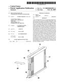
[0014]FIG. 1 is a perspective view of a gas cooler according to an embodiment of the present invention.
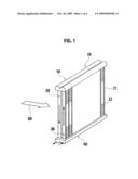
[0015]FIG. 2 is a vertical sectional view of FIG. 1.
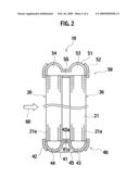
[0016]FIG. 3 is a p-h diagram showing an operation of a refrigeration cycle using a CO2 refrigerant according to the embodiment.
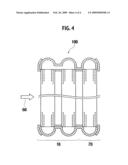
[0017]FIG. 4 is a sectional view of an example of the gas cooler according to the embodiment that is constituted as a UCR.
BEST MODE FOR CARRYING OUT THE INVENTION
[0018]An embodiment of a heat exchanger and an integrated-type heat exchanger according to the present invention will be explained below. An example of the heat exchanger of the present invention that is applied to a vertically-flowing type gas cooler using CO2 as a refrigerant is explained here.
[0019]FIG. 1 is a perspective view of a gas cooler according to the embodiment, and FIG. 2 is a vertical sectional view of FIG. 1.
[0020]As shown in FIG. 1, a gas cooler 10 according to the embodiment includes a first heat exchanger core 20 and a second heat exchanger core 30 that exchange heat between a refrigerant that passes through the gas cooler 10 and cooling air 60, a first header tank 40 that is joined to lower ends of the first heat exchanger core 20 and the second heat exchanger core 30, and a second header tank 50 that is joined to upper ends of the first heat exchanger core 20 and the second heat exchanger core 30.
[0021]Each of the first heat exchanger core 20 and the second heat exchanger core 30 has a structure in which porous tubes 21 formed with a plurality of tube holes 21a functioning as refrigerant paths, and corrugated cooling fins 22 are alternately laminated. The first heat exchanger core 20 and the second heat exchanger core 30 are placed in front and back positions, respectively, such that the first heat exchanger core 20 is located frontward with respect to the flowing direction of the cooling air 60 (on the windward side of the cooling air 60) and the second heat exchanger core 30 is located backward (on the leeward side of the cooling air 60).
[0022]As shown in FIG. 2, the first header tank 40 is located under the first and second heat exchanger cores 20 and 30, and includes two plates 41 and 42 superposed and joined to each other by brazing. A first tank portion 43 and a second tank portion 44 are formed in the first header tank 40. The first tank portion 43 and the second tank portion 44 have substantially semi-circular cross sections, and they function as flowing paths of the refrigerant. The first tank portion 43 and the second tank portion 44 are separated from each other at the central portion in the first header tank 40. The first tank portion 43 and the second tank portion 44 are formed as independent tank portions which are not in communication with each other in the first header tank 40. A refrigerant supply pipe (not shown) is connected to the first tank portion 43, and a refrigerant discharge pipe (not shown) is connected to the second tank portion 44.
[0023]In the first header tank 40, the first tank portion 43 located on the leeward side as viewed from a flowing direction of the cooling air 60 is in communication with a refrigerant-inlet side of the second heat exchanger core 30, and the second tank portion 44 located on the windward side is in communication with a refrigerant-outlet side of the first heat exchanger core 20. With this design, the refrigerant is introduced from the first tank portion 43 located on the leeward side, and the refrigerant is discharged from the second tank portion 44 located on the windward side.
[0024]As shown in FIG. 2, the second header tank 50 is placed on the first and second heat exchanger cores 20 and 30, and includes two plates 51 and 52 superposed and joined to each other by brazing. A first tank portion 53 and a second tank portion 55 are formed in the second header tank 50. The first tank portion 53 and the second tank portion 55 have substantially semi-circular cross sections, and they function as flowing paths of the refrigerant. A communication path 55 is formed between the first tank portion 53 and the second tank portion 54, and these tank portions 54 and 55 are in communication with each other.
[0025]In the second header tank 50, the first tank portion 53 is in communication with a refrigerant-outlet side of the second heat exchanger core 30, and the second tank portion 54 is in communication with a refrigerant-inlet side of the first heat exchanger core 20. With this design, the refrigerant that has passed through the second heat exchanger core 30 flows from the first tank portion 53 of the second header tank 50 to the second tank portion 54 through the communication path 55, and then flows into the first heat exchanger core 20.
[0026]In the gas cooler 10 having the above-described structure, the refrigerant introduced from the first tank portion 43 of the first header tank 40 flows upward through the tube holes 21 (see FIG. 2) of the second heat exchanger core 30 and flows into the first tank portion 53 of the second header tank 50. The refrigerant further flows through the communication path 55 into the second tank portion 54, and flows downward through the tube holes 21 of the first heat exchanger core 20, flows into the second tank portion 44 of the first header tank 40, and is discharged outside from the second tank portion 44. During this time, heat is exchanged between the refrigerant and the cooling air 60 that flows in a direction intersecting with the flowing direction of the refrigerant when the refrigerant passes through the heat exchanger cores 20 and 30.
[0027]FIG. 3 is a p-h diagram showing an operation of a refrigeration cycle using a CO2 refrigerant, and shows cycle balance at the time of cooling operation. In FIG. 3, a section on a high pressure side (a-b) that is equal to or higher than a critical point shows variation in the gas cooler.
[0028]When a temperature of outside air is 40° C. or the like and a load is high, the refrigerant is gaseous also in the vicinity of the outlet of the gas cooler 10, and a high flow rate can be maintained even if the refrigerant flows vertically Thus, retention of oil does not occur.
[0029]On the other hand, when a temperature of outside air is 15° C. or the like and a load is low, the refrigerant becomes a liquid refrigerant because the refrigerant condenses. However, the refrigerant is gaseous when it passes through the first path (second heat exchanger core 30) and the flow rate is high. Thus, it is easy to discharge oil upward. When the refrigerant passes through the second path (first heat exchanger core 20), the refrigerant flows downward. The refrigerant flows downward by its own weight, and therefore oil can be easily discharged. Thus, retention of oil does not occur even at the time of low load.
[0030]According to the structure of the embodiment as explained above, the refrigerant flows upward on the leeward side of the first header tank 40, turns around in the second header tank 50, and flows downward on the windward side. Therefore, oil does not stay together with the refrigerant in the second header tank 50 or first heat exchanger core 20, and can flow downward. Thus, the pressure of the refrigerant is not increased or decreased during the operation of the refrigeration cycle, and hunting can be suppressed. Therefore, it is possible to keep the temperature of the adjusted air constant.
[0031]According to the structure of the embodiment, because the number of paths of the refrigerant is two, the heat exchanging region is greater as compared with a structure having only one path, and it is possible to prevent the deterioration of the heat radiation performance. Because the number of paths of the refrigerant is two, the refrigerant can easily turn, and the path resistance can be reduced as compared with a structure having three paths. As a result, it is possible to prevent oil from staying in the path as compared with a structure having three paths. Because the number of paths of the refrigerant is two, it is possible to prevent hunting caused by retention of oil without deteriorating the heat radiation performance while using the gas cooler of the vertically-flowing type.
[0032]Further, because the refrigerant is introduced from the leeward side (first tank portion 43) of the first header tank 40, the temperature of the refrigerant passing on the leeward side is higher than the temperature of the refrigerant passing on the windward side. Therefore, even if cooling air having passed through the first and second heat exchanger cores flows back into the opposite direction, it is possible to increase a difference between the temperature of the cooling air flowed back and the refrigerant temperature, which reduces the influence exerted on the heat radiation performance.
[0033]Because the first tank portion 43 and the second tank portion 44 can be placed so that they are separated from each other in the front and back positions as viewed from the flowing direction of cooling air, it is possible to suppress heat exchange between a relatively high-temperature refrigerant introduced into the first tank portion 43 of the first header tank 40 and a refrigerant that has subjected to heat exchange with the cooling air while having passed through the first heat exchanger core 20 and then the second heat exchanger core 30, and that has become low in temperature. Therefore, it is possible to enhance the heat exchange efficiency.
[0034]As shown in FIG. 2, it is possible to use the first header tank 40 in which slits 41a and 42a are provided along the longitudinal direction of the first header tank 40 at the central portions of the plates 41 and 42 constituting the first tank portion 43 and the second tank portion 44, and the two tank portions 43 and 44 are connected to each other in at least one position (preferably two or more positions). If such slits 41a and 42a are provided, heat is less prone to be transmitted from the first tank portion 43 to which the high temperature refrigerant is introduced to the second tank portion 44 from which the low temperature refrigerant is discharged. Thus, it is possible to further enhance the heat exchange efficiency.
[0035]Furthermore, when the slits 41a and 42a are provided, a shielding member 45 may be pasted so as to cover a space between the first tank portion 43 and the second tank portion 44 as shown in FIG. 2. If such a shielding member 45 is provided, it is possible to prevent a situation in which the cooling air which has passed through the first heat exchanger core 20 located on the windward side passes downward through the slits 41a and 42a. Thus, deterioration of heat exchange efficiency caused by the slits 41a and 42a can be suppressed. To make is difficult for heat from being transmitted from the first tank portion 43 to the second tank portion 44, it is preferable to use a resin material having low thermal conductivity as the shielding member 45.
[0036]The gas cooler 10 according to the embodiment may be integrated with a radiator into a UCR as shown in FIG. 4. FIG. 4 is a vertical sectional view of an UCR 100 that is formed by integrally providing a vertically-flowing type radiator 70 on the leeward side of the gas cooler 10.
[0037]As shown in FIG. 4, when the gas cooler 10 according to the embodiment is combined with the vertically-flowing type radiator 70, parts can be formed integrally as one unit, and its structure can be simplified, and thus cost thereof can be reduced. Further, even when the gas cooler is placed between cross members of a vehicle, upper and lower header tanks can be located behind the cross members. Therefore, an air-passing area is not reduced unlike a case of using the laterally-flowing type radiator, and it is unnecessary to increase its thickness. Thus, it is possible to effectively utilize a space in the engine room.
INDUSTRIAL APPLICABILITY
[0038]According to the present invention, engine cooling performance can be enhanced, the heat exchanger can be reduced in size as compared with a case of using the laterally-flowing type radiator, and an amount of engine cooling water can also be reduced. Thus, a vehicle can be reduced in weight.
User Contributions:
comments("1"); ?> comment_form("1"); ?>Inventors list |
Agents list |
Assignees list |
List by place |
Classification tree browser |
Top 100 Inventors |
Top 100 Agents |
Top 100 Assignees |
Usenet FAQ Index |
Documents |
Other FAQs |
User Contributions:
Comment about this patent or add new information about this topic:
Images included with this patent application:
 |  |
 |  |
| Similar patent applications: | |
| Date | Title |
|---|---|
| 2013-05-23 | Heat exchanger plate and a plate heat exchanger |
| 2013-05-16 | Spiral exchanger and method for manufacturing such an exchanger |
| 2013-05-23 | Heat exchanger and refrigeration and air-conditioning apparatus |
| 2013-05-23 | Enhanced surface area for sideplate heat exchanger bracket |
| 2011-12-01 | Port opening of brazed heat exchanger |
| New patent applications in this class: | |
| Date | Title |
|---|---|
| 2016-12-29 | Nanofluids containing carbon nanotubes and metal oxide nanoparticle composites with enhanced heat transfer and heat capacity properties |
| 2016-07-07 | An inlet system for a thermal storage vessel |
| 2016-07-07 | Heat exchanger having arcuately and linearly arranged heat exchange tubes |
| 2016-06-23 | Motor stator cooling with dual coolant two-phase heat exchanger |
| 2016-05-26 | Heat exchanger with an adapter unit fixed to an endplate, and associated method of manufacture |
| New patent applications from these inventors: | |
| Date | Title |
|---|---|
| 2010-08-19 | Vehicle air conditioning system |
| Top Inventors for class "Heat exchange" | |
| Rank | Inventor's name |
|---|---|
| 1 | Levi A. Campbell |
| 2 | Chun-Chi Chen |
| 3 | Tai-Her Yang |
| 4 | Robert E. Simons |
| 5 | Richard C. Chu |