Patent application title: Hydronic floor heating system with adaptive fluid circuit
Inventors:
Meng Yeow Foo (Virum, DK)
Timmy Sze Ming Foo (Virum, DK)
IPC8 Class: AF24D316FI
USPC Class:
165 56
Class name: Structural installation related to wall, floor or ceiling structure of a chamber hollow or recess in the structure connected for exchange fluid flow
Publication date: 2009-01-15
Patent application number: 20090014152
uses separate heating panels fastened to a
sub-floor to conduct a heating fluid which then adjusts the temperature
of a room. The panels carry fluid tubing and transition panels conduct
this tubing between the heating panels. The transition panels have a
plurality of grooves that allow the selection of how the tubing is
conducted between the heating panels so that a custom heating circuit may
be formed to optimize the heating pattern of each installation.Claims:
1. An apparatus comprising: a heating panel made up of a plurality of
side-by-side planks; each said plank providing a planar mounting surface
having therein a linear groove extending longitudinally between opposing
ends of the plank; each one of the planks having a continuous metal sheet
covering the mounting surface and the respective linear groove therein;
each pair of the side-by-side planks joined by a hinge means enabling the
side-by-side planks to rotate between a coplanar state and a stacked
state; a pair of transition panels abutting the ends of heating panel,
each said transition panel providing a first set of curved grooves
extending between the linear grooves of adjacent pairs of the planks, a
second set of the curved grooves extending between the linear grooves of
non-adjacent pairs of the planks, and a further linear groove connecting
the second set of curved grooves.
2. The apparatus of claim 1 further comprising tubing engaged within selected portions of the linear and curved grooves for conducting heating fluid therethrough.
3. The apparatus of claim 2 wherein the tubing is secured within the grooves by a bonding agent.
4. The apparatus of claim 3 further comprising a layer of sound insulation and heat conduction padding laid on top of the heating panel to improve heat transmission to the flooring on top, and provide better impact absorption and sound insulation.
5. A method of providing a heated floor comprising the steps of:a) providing a plurality of heating panels each made up of a plurality of side-by-side planks; each said plank providing a planar mounting surface having therein a linear groove extending longitudinally between opposing ends of the plank; each one of the planks having a continuous metal sheet covering the mounting surface and the respective linear groove therein;b) providing a plurality of pairs of transition panels abutting the opposing ends of the planks, each said transition panel providing a first set of curved grooves extending between the linear grooves of adjacent pairs of the planks, and a second set of the curved grooves extending between the linear grooves of non-adjacent pairs of the planks;c) fastening the heating panels and the transition panels to a sub-floor surface;d) engaging tubing within selected portions of the linear and curved grooves for conducting heating fluid therethrough;e) securing the tubing within the linear and curved grooves using a bonding agent; andf) covering the heating and transition panels with a layer of sound insulation and heat conduction padding.
6. The method of claim 5 wherein the tubing is engaged with each one of the linear grooves in at least one of a series and a parallel arrangement.
7. The method of claim 5 wherein the tubing is engaged with non-adjacent ones of the linear grooves in at least one of a series and a parallel arrangement.Description:
CROSS-REFERENCE TO RELATED APPLICATIONS
[0001]Not applicable.
STATEMENT REGARDING FEDERALLY SPONSORED RESEARCH OR DEVELOPMENT
[0002]Not applicable.
THE NAMES OF THE PARTIES TO A JOINT RESEARCH AGREEMENT
[0003]Not applicable.
INCORPORATION-BY-REFERENCE OF MATERIAL SUBMITTED ON A COMPACT DISC
[0004]Not applicable.
REFERENCE TO A "MICROFICHE APPENDIX"
[0005]Not applicable.
BACKGROUND OF THE INVENTION
[0006]1. Field of the Present Disclosure
[0007]This disclosure relates generally to heating systems for living and working spaces and more particularly to a hydronic floor heating system adaptable to a wide range of circuit configurations.
[0008]2. Description of Related Art Including Information Disclosed Under 37 CFR 1.97 and 1.98
[0009]Williams, U.S. Pat. No. 3,037,746 discloses a floor covering for radiant heating installations, utilizing tiles for installation against a flat surface such as a floor, wall, ceiling, etc. for covering a heating element overlying that surface. The objectives of this invention can be obtained by positioning an elongated heating element on the surface in a sinuous pattern and covering it with relatively large tiles, preferably molded of plastic material, these tiles being grooved to receive sections of the sinuous heating element. One of the important features of the invention is to provide a tile which is so grooved that it can be used to cover both straight runs and curved end sections of a sinuous heating element.
[0010]Bourne, U.S. Pat. No. 4,782,889 discloses a low mass hydronic radiant floor heating system for heating a room by circulating a liquid, the system including a metal deck having a plurality of regularly spaced troughs to provide structural strength. The deck is adapted to be secured directly to a plurality of floor joists. Tubing is placed in the troughs to distribute heat by circulating warm liquid through the tubing. The troughs of the metal deck support structural floor loads while providing a housing for the tubing. Flat portions of the deck between the troughs distribute heat laterally.
[0011]Shiroki, U.S. Pat. No. 4,865,120 discloses a floor structure for heating a timber-framed house, with which the floor of the house can be kept warm for a while even after the circulation of hot water in the hot water pipe has been stopped, whereas the pipe can be reduced in length as well. In achieving an object as above, a floor structure for heating according to the present invention comprises: a wooden board; a wooden frame secured on the wooden board; a heat accumulating layer which is inserted and fitted inside the frame on the wooden board; a plurality of grooves extending from one edge of the wooden frame by way of the surface of the heat accumulating layer to the other edge relative to the one end thereof; and a metal plate which is inserted in these grooves, covers the surface of the heat accumulating layer and its contiguous surface of the wooden frame, and is fitted on the wooden frame.
[0012]Fiedrich, U.S. Pat. No. 5,292,065 and U.S. Pat. No. 5,579,996 disclose a hydronic heating system that has a boiler supplying hot supply water, a reservoir of cooler return water, a supply water line, a return water line and one or more heating loops through which water flows from the supply line to the return line, the heating loops including a heating element that is a length of tubing that conducts water from the supply to the return and is mounted in a wall or a floor of an area heated by said system by RFH or RWH has: a thermally conductive plate mounted in the area floor or wall, adjacent a surface thereof and board-like members for holding the plate and the length of tubing in intimate thermal contact with the plate, so that the plate is heated by conduction of heat from the tubing and the plate has a radiating surface that radiates heat to the area. The plate and board-like members with an elongated space for holding the tubing is provided as a modular piece and several such modular pieces are arranged in line attached to the sub-flooring for RFH, or the wall studs for RWH, for insertion of the length of tubing in the aligned slots thereof; and following such insertion, the installation is ready for a finishing floor or wall covering. Thus, RFH or RWH is installed "dry" (without wet concrete, cement, or plaster) and can be accessed later by removing the finishing cover.
[0013]Pickard et al, U.S. Pat. No. 5,454,428 discloses an extruded aluminum radiant heat transfer plate including an integral elongated receptacle for holding and confining a plastic tubing. The aluminum radiant heat transfer plate is extruded to provide heat transfer side edges in the form of thin-walled fins running the length of the extrusion. Between the fins, the extrusion provides the elongated receptacle for the plastic tubing. The receptacle can take the form of a "C" that stands above the plane of the heat transfer fins. The receptacle, alternately, can take the form of a "U," the legs of which integrally connect to the fins.
[0014]Alsberg, U.S. Pat. No. 5,788,152 discloses in combination, a radiant panel heating system, configured for ease of installation and maintenance which also provides the structural characteristics required of a sub-flooring panel within a floor framing system. The system consists of structural sub-flooring panels with grooves arrayed in a modular geometry. The panels are overlaid with a heat-conducting surface embossed with a matching groove pattern. The panels are capable of being fastened to a variety of floor support structures in a manner typical of sub-floor panels, which fulfill a structural requirement only while simultaneously interacting to create an array of approximately evenly spaced grooves into which tubing or wire of the type used in hydronic or electric radiant panel heating is installed.
[0015]Fiedrich, U.S. Pat. No. 5,931,381 discloses in radiant floor, wall and/or ceiling hydronic heating and/or cooling systems using metal radiation plates that are heated or cooled by attached tubing that is fed hot or cold water, where the system includes a plurality of aligned modular heating and/or cooling panels attached to the floor, wall and ceiling, each panel containing a metal radiation plate and each holds a length of the same tubing, the tubing being inserted into an accommodation in the panel and held therein in intimate thermal contact with the plate, and the assembly of panels with tubing inserted is covered with a finished floor, wall or ceiling and then hot water for heating or cold water for cooling is fed to the tubing, a thermal barrier is provided between the panels and the finished floor, wall or ceiling to: diminish or eliminate "hot spots" in the surface of the finished flooring, wall covering and ceiling covering during heating and "cold spots" during cooling; avoid condensation during cooling; and improve performance.
[0016]Fiedrich, U.S. Pat. No. 6,270,016 discloses in a hydronic radiant heating and/or cooling system modular panels each of a metal plate or sheet on a board or boards providing a slot into which tubing is inserted and held against the plate in intimate thermal contact therewith, so that the plate is heated/cooled by conduction of heat between the water in the tubing and the plate, the improvement in which two or more of said panels are hinged together, side by side or end to end to provide a hinged set of panels so that two or more of sets of hinged panels unfolded at their hinges and arranged side by side on a floor, wall or ceiling provide elongated spaces into which said tubing is inserted and held against said radiation plate a finished floor, wall or ceiling covering can be installed thereon and said system operated to heat or cool said room.
[0017]Chiles et al, U.S. Pat. No. 6,726,115 discloses a radiant heating system for installation on a sub-floor. Header panels having arcuate cutouts are secured on the sub-floor near opposite walls of a room. Spaced apart sleepers are secured to extend between the header panels and provide channels that receive radiant heating tubing. The cutouts are initially occupied by break away header plates which can be detached to allow the tubing to curve through the cutouts so that it can extend between the ends of adjacent channels. The cutouts can be inserted back into the cutouts to secure the tubing bends in place. Heat conductive panels overlie the sleepers and channels and can be overlaid with finished flooring.
[0018]Rodin, U.S. Pat. No. 6,739,097 discloses a floor element, for floor heating systems and the like, and a method of manufacturing such element. The element includes a sheet having at least one channel and a heat transfer layer which extends over one main surface of the sheet and on each side of respective channels, and forms an upwardly open recess that receives a heat transfer conductor and tightly embraces the conductor around half its circumference in the channel, with the upper side of the conductor being flush with or lower than the upper side of the sheet. The heat transfer layer is preferably made of thin, readily flexed foil that has a thickness of less than 200 m.
[0019]Seki et al, U.S. Pat. No. 6,776,222 discloses a foldable floor heating panel that can be folded longitudinally and laterally. The foldable floor heating panel includes several small plate-like members of a rectangular plan configuration, which are arranged longitudinally and laterally so as to be adjacent to each other. A flexible thin plate is attached to upper surfaces of the small plate-like members so as to allow longitudinal and lateral folding. Heat carrier flexible tube passages are provided in longitudinal and lateral folding portions of the panel so as to leave some play, and folding margin members are provided at the lateral folding portions. Fit-in members are attachably and detachably provided in respective heat carrier flexible tube passages with some play.
[0020]The related art described above discloses foldable floor heating panels, grooves for heating devices, use of a metal sheet conductive layer, cemented mounting of tubes, and headers for tube transfer. However, the prior art fails to disclose the use of a plurality of elongated panels each foldable for stacking in an accordion style. Additionally, the prior art teaches floor heating systems which conduct hot water through a single series circuit of tubing. It fails, however, to teach a system with the capability to selectively conduct a range of circuit configurations including both series and parallel circuits. The present disclosure distinguishes over the prior art providing heretofore unknown advantages as described in the following summary.
BRIEF SUMMARY OF THE INVENTION
[0021]This disclosure teaches certain benefits in construction and use which give rise to the objectives described below.
[0022]Hydronic floor heating is a well-known technique of heating living and working spaces. However, as mentioned above, much of the prior art discloses heating panels which tend to be difficult to store and transport due to their size. This, in turn, can make storage, transportation, and installation rather expensive. The presently described apparatus provides a solution to this problem by enabling the heating panels to fold in a compact accordion fashion for storage and transport.
[0023]In addition, the prior art teaches heating systems which conducts hot water through tubing in a series circuit. This obviously leads to gradual cooling of the water as it travels through the tubing, thus creating a thermal gradient across the floor. The presently described apparatus provides a solution to this problem, creating faster and more uniform heat dispersal, by enabling the tubing to be run in both series and parallel circuits and with a circuit density as desired.
[0024]The present invention uses flat foldable heating panels that are placed in adjacency and fastened over a supporting sub-floor. These heating panels receive conducting tubes for the transfer of heating fluids, and transition panels provide selective configuration of the fluid flow between panels. The heating panels are segmented for folding in a stacked arrangement for easy transport and installation.
[0025]A primary objective inherent in the above described apparatus and method of use is to provide advantages not taught by the prior art.
[0026]A further objective is to provide such a floor heating system that provides a choice of water flow path arrangements.
[0027]A still further objective is to provide a hydronic floor heating system that is easily transported.
[0028]A still further objective is to provide such a floor heating system that is compactly stored when not installed.
[0029]An even further objective is to provide such a floor heating system for which installation is relatively easy and inexpensive.
[0030]Other features and advantages of the present invention will become apparent from the following more detailed description, taken in conjunction with the accompanying drawings, which illustrate, by way of example, the principles of the presently described apparatus and method of its use.
BRIEF DESCRIPTION OF THE SEVERAL VIEWS OF THE DRAWING(S)
[0031]Illustrated in the accompanying drawing(s) is at least one of the best mode embodiments of the present invention In such drawing(s):
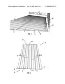
[0032]FIG. 1 is a perspective view of portions of panels of the present invention as installed on a sub-floor of a room;
[0033]FIG. 2 is a perspective view of a heating panel thereof having panel segments arranged in a co-planar orientation;
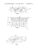
[0034]FIG. 3 is an end view thereof with the panel segments shown in a partially folded state;
[0035]FIG. 4 is a top plan view of a portion of a transition panel thereof abutting an end of a heating panel;
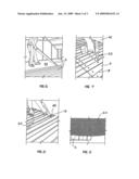
[0036]FIG. 5 is a partial perspective view thereof showing a metal sheet being placed onto a panel segment; and
[0037]FIGS. 6 through 9 are partial perspective views depicting stages of installation including respectively: laying heating panels, fastening the panels to the sub-floor, fastening tubing to the metal sheets, and covering the panels and metal sheets with a sound insulation and heat conduction padding.
DETAILED DESCRIPTION OF THE INVENTION
[0038]The above described drawing figures illustrate the described apparatus and its method of use in at least one of its preferred, best mode embodiment, which is further defined in detail in the following description. Those having ordinary skill in the art may be able to make alterations and modifications to what is described herein without departing from its spirit and scope. Therefore, it must be understood that what is illustrated is set forth only for the purposes of example and that it should not be taken as a limitation in the scope of the present apparatus and method of use.
[0039]Described now in detail, and illustrated in the figures, is a preferred embodiment of the present invention, a hydronic floor heating apparatus adaptable to various installation sizes and fluid conducting circuit arrangements as a system. The apparatus is modular comprising a plurality of heating and transition panels and fluid conductors. Heating panels 2 (FIG. 2) are each made up of a plurality of panel segments, referred to herein as planks 4. Each plank 4 contains a linear groove 8 extending medially and longitudinally between opposing ends 10 of the plank 4 on its mounting surface 12. Additionally, each plank 4 has a continuous metal sheet 14 covering the mounting surface 12 (FIG. 5) and also fastened into the respective linear groove 8. The planks 4 are positioned in side-by-side juxtaposition and joined by a hinge 6, which may be plural individual hinges 6 or one continuous hinge 6 and may be made of cloth, duct tape, or other similar materials which will be known to those of skill in the art. The hinges 6 are positioned on alternate sides of planks 4 enabling the side-by-side planks 4 to fold in accordion fashion between a coplanar arrangement, shown in FIG. 2, and a stacked arrangement where the planks 4 are folded in the manner shown in FIG. 3 so that they lay face-to-face, i.e., with mounting surfaces 12 touching.
[0040]A transition panel 30 abuts each of the ends 10 of the heating panel 2, and each panel 30 provides a first set of curved grooves 32 extending between the linear grooves 8 of adjacent pairs of the planks 4, and a second set of curved grooves 34 extending between the linear grooves 8 of non-adjacent pairs of the planks 4 (FIG. 4). In addition, a further linear groove 36 connects the second set of curved grooves, allowing for even more water flow path arrangements.
[0041]Preferably, each heating panel 2 is rectangular in shape when in the unfolded state (FIG. 2), and is made up of six of the planks 4, preferably measuring 40 inches wide by 48 inches long; however, more or less planks 4, as well as other sizes and shapes may be used without a loss of efficacy of the invention. Each plank 4 is preferably made of construction grade plywood so that it has flat surfaces and is dimensionally stable. Therefore, the planks 4 expand or contract minimally with temperature changes. Of course, other structural materials with similar engineering characteristics may be substituted in this application.
[0042]As demonstrated in FIG. 5, the metal sheet 14 is mounted on the mounting surface 12, preferably using a glue or similar bonding agent, and extends longitudinally between ends 10. Each metal sheet 14 has a sheet upset 16, preferably a rectangular notch, which fits intimately within the linear groove 8 when the metal sheet 14 is mounted on plank 4. The metal sheets 14 are preferably made of a good thermal conductor such as aluminum. Use of aluminum sheets enables the apparatus to efficiently disperse and transfer heat away from the linear grooves 8 so that the metal sheets 14 maintain a uniform temperature across their full width and length without appreciable thermal gradients even when warming up or cooling down.
[0043]Tubing 20 is mounted with a bonding agent 44 within selected ones of upsets 16 and grooves 32, 34, 36 as desired. The upsets 16 and grooves 32, 34, 36 are deep enough to secure tubing 20 below the respective outer surfaces. The tubing 20 is preferably made of cross-linked polyethylene material, which allows it to maintain its required flexibility and strength over a range of temperatures that might be experienced at the installation site. Other tubing materials may be substituted depending on particular environmental situations.
[0044]As shown in FIG. 1, when installing the present apparatus, a pair of transition panels 30 is used, abutting the ends of each heating panel 2. The purpose of these transition panels 30, shown in greater detail in FIG. 4, is to allow for a variety of placement patterns for tubing 20 during installation. For example, tubing 20 may be placed within each one of the sheet upsets 16. In an alternative arrangement, tubing 20 may be placed within every other upset 16, thus leaving some of the upsets 16 without tubing 20. In addition, a first path of tubing 20 may be placed within alternating upsets 16 utilizing the first set of curved grooves 32, while a second path of tubing 20 is placed within the other upsets 16 utilizing the second set of curved grooves 34 and the further linear groove 36. Thus, the transition panels 30 allow for a variety of desired installation patterns, including both series and parallel circuits, which the installer can choose on site without additional modifications. Enabling the apparatus to run parallel circuits of hot water creates a more uniform dispersal of heat, thus avoiding the potential problem of water gradually cooling in a series circuit which might, create thermal gradients in the space being heated. While the preferred embodiment of each transition panel 30 includes a first 32 second 34 set of curved grooves, and a further linear groove 36, clearly, it may have any plurality of sets of curved grooves and linear grooves.
[0045]Parquet and, in particular, laminate floors are sensitive to humidity. In addition, damp proofing is necessary in new buildings and cellars, and also in the case of repaired screeds in refurbished buildings. As shown in FIG. 6, the heating panel 2 is being laid over the sub-floor 40. The sub-floor 40 should have already been made moisture-proof with a layer of Polyethylene (PE) foil or similar water-proofing materials which will be known to those of skill in the art, as required by local building law and regulation. A layer of moisture and heat insulation padding is recommended to be laid on top of the PE foil to prevent downward heat transmission to the layers below. On top of the heating panels 2, a heat conduction and sound proofing padding 24 is laid. This improves heat transmission to the flooring on top, and provides better impact absorption and sound insulation. Other material will be known to persons with ordinary skill in the art and may be substituted.
[0046]The method of installation of the present apparatus is quick and simple. After the accordion stacked planks 4 are moved into the room, they are unfolded to form the planar heating panels 2. The panels 2 are then placed onto the prepared sub-floor 40 of the room. A plurality of heating panels 2 are used, as necessary, in order to cover the entire sub-floor 40 of the room, as illustrated in FIG. 1. This is accomplished by placing the heating panels 2 in an abutting coplanar arrangement, side-by-side and end-to-end with the linear grooves 8 oriented in parallel and collinear as shown (FIG. 6).
[0047]Transition panels 30 are then positioned, abutting the ends of each of the heating panels 2. The transition panels 30 are positioned as shown in FIG. 4, enabling the transition of the tubing 20 between the upsets 16 and the corresponding curved grooves 32, 34, 36.
[0048]Next, each of the heating panels 2 and transition panels 30 are secured to the sub-floor 40 using fasteners 42, such as screws or similar hardware, as shown in FIG. 7. Tubing 20 is then engaged within selected ones of the upsets 16 and grooves 32, 34, 36, as desired by the installer, to create a continuous path, or plurality of continuous paths, allowing fluids to flow through the panels. The tubing 20 is permanently secured using an appropriate bonding agent 44, as shown in FIG. 8.
[0049]Finally, a sound insulation and heat conduction padding 24 is placed over the heating panel 2, as shown in FIG. 9. Wood, vinyl, or laminated flooring may now be installed on top. For carpeted flooring, plywood backer sheet may be placed on top of the padding 24. For tile flooring, thin liquid cement may be layered directly on top of the heating panel 2. The tubing ends are connected to a hot water source, and pump if necessary, thus enabling hot water to travel through the floor continuously in order to heat the room.
[0050]The enablements described in detail above are considered novel over the prior art of record and are considered critical to the operation of at least one aspect of the apparatus and its method of use and to the achievement of the above described objectives. The words used in this specification to describe the instant embodiments are to be understood not only in the sense of their commonly defined meanings, but to include by special definition in this specification: structure, material or acts beyond the scope of the commonly defined meanings. Thus if an element can be understood in the context of this specification as including more than one meaning, then its use must be understood as being generic to all possible meanings supported by the specification and by the word or words describing the element.
[0051]The definitions of the words or drawing elements described herein are meant to include not only the combination of elements which are literally set forth, but all equivalent structure, material or acts for performing substantially the same function in substantially the same way to obtain substantially the same result. In this sense it is therefore contemplated that an equivalent substitution of two or more elements may be made for any one of the elements described and its various embodiments or that a single element may be substituted for two or more elements in a claim.
[0052]Changes from the claimed subject matter as viewed by a person with ordinary skill in the art, now known or later devised, are expressly contemplated as being equivalents within the scope intended and its various embodiments. Therefore, obvious substitutions now or later known to one with ordinary skill in the art are defined to be within the scope of the defined elements. This disclosure is thus meant to be understood to include what is specifically illustrated and described above, what is conceptually equivalent, what can be obviously substituted, and also what incorporates the essential ideas.
[0053]The scope of this description is to be interpreted only in conjunction with the appended claims and it is made clear, here, that each named inventor believes that the claimed subject matter is what is intended to be patented.
Claims:
1. An apparatus comprising: a heating panel made up of a plurality of
side-by-side planks; each said plank providing a planar mounting surface
having therein a linear groove extending longitudinally between opposing
ends of the plank; each one of the planks having a continuous metal sheet
covering the mounting surface and the respective linear groove therein;
each pair of the side-by-side planks joined by a hinge means enabling the
side-by-side planks to rotate between a coplanar state and a stacked
state; a pair of transition panels abutting the ends of heating panel,
each said transition panel providing a first set of curved grooves
extending between the linear grooves of adjacent pairs of the planks, a
second set of the curved grooves extending between the linear grooves of
non-adjacent pairs of the planks, and a further linear groove connecting
the second set of curved grooves.
2. The apparatus of claim 1 further comprising tubing engaged within selected portions of the linear and curved grooves for conducting heating fluid therethrough.
3. The apparatus of claim 2 wherein the tubing is secured within the grooves by a bonding agent.
4. The apparatus of claim 3 further comprising a layer of sound insulation and heat conduction padding laid on top of the heating panel to improve heat transmission to the flooring on top, and provide better impact absorption and sound insulation.
5. A method of providing a heated floor comprising the steps of:a) providing a plurality of heating panels each made up of a plurality of side-by-side planks; each said plank providing a planar mounting surface having therein a linear groove extending longitudinally between opposing ends of the plank; each one of the planks having a continuous metal sheet covering the mounting surface and the respective linear groove therein;b) providing a plurality of pairs of transition panels abutting the opposing ends of the planks, each said transition panel providing a first set of curved grooves extending between the linear grooves of adjacent pairs of the planks, and a second set of the curved grooves extending between the linear grooves of non-adjacent pairs of the planks;c) fastening the heating panels and the transition panels to a sub-floor surface;d) engaging tubing within selected portions of the linear and curved grooves for conducting heating fluid therethrough;e) securing the tubing within the linear and curved grooves using a bonding agent; andf) covering the heating and transition panels with a layer of sound insulation and heat conduction padding.
6. The method of claim 5 wherein the tubing is engaged with each one of the linear grooves in at least one of a series and a parallel arrangement.
7. The method of claim 5 wherein the tubing is engaged with non-adjacent ones of the linear grooves in at least one of a series and a parallel arrangement.
Description:
CROSS-REFERENCE TO RELATED APPLICATIONS
[0001]Not applicable.
STATEMENT REGARDING FEDERALLY SPONSORED RESEARCH OR DEVELOPMENT
[0002]Not applicable.
THE NAMES OF THE PARTIES TO A JOINT RESEARCH AGREEMENT
[0003]Not applicable.
INCORPORATION-BY-REFERENCE OF MATERIAL SUBMITTED ON A COMPACT DISC
[0004]Not applicable.
REFERENCE TO A "MICROFICHE APPENDIX"
[0005]Not applicable.
BACKGROUND OF THE INVENTION
[0006]1. Field of the Present Disclosure
[0007]This disclosure relates generally to heating systems for living and working spaces and more particularly to a hydronic floor heating system adaptable to a wide range of circuit configurations.
[0008]2. Description of Related Art Including Information Disclosed Under 37 CFR 1.97 and 1.98
[0009]Williams, U.S. Pat. No. 3,037,746 discloses a floor covering for radiant heating installations, utilizing tiles for installation against a flat surface such as a floor, wall, ceiling, etc. for covering a heating element overlying that surface. The objectives of this invention can be obtained by positioning an elongated heating element on the surface in a sinuous pattern and covering it with relatively large tiles, preferably molded of plastic material, these tiles being grooved to receive sections of the sinuous heating element. One of the important features of the invention is to provide a tile which is so grooved that it can be used to cover both straight runs and curved end sections of a sinuous heating element.
[0010]Bourne, U.S. Pat. No. 4,782,889 discloses a low mass hydronic radiant floor heating system for heating a room by circulating a liquid, the system including a metal deck having a plurality of regularly spaced troughs to provide structural strength. The deck is adapted to be secured directly to a plurality of floor joists. Tubing is placed in the troughs to distribute heat by circulating warm liquid through the tubing. The troughs of the metal deck support structural floor loads while providing a housing for the tubing. Flat portions of the deck between the troughs distribute heat laterally.
[0011]Shiroki, U.S. Pat. No. 4,865,120 discloses a floor structure for heating a timber-framed house, with which the floor of the house can be kept warm for a while even after the circulation of hot water in the hot water pipe has been stopped, whereas the pipe can be reduced in length as well. In achieving an object as above, a floor structure for heating according to the present invention comprises: a wooden board; a wooden frame secured on the wooden board; a heat accumulating layer which is inserted and fitted inside the frame on the wooden board; a plurality of grooves extending from one edge of the wooden frame by way of the surface of the heat accumulating layer to the other edge relative to the one end thereof; and a metal plate which is inserted in these grooves, covers the surface of the heat accumulating layer and its contiguous surface of the wooden frame, and is fitted on the wooden frame.
[0012]Fiedrich, U.S. Pat. No. 5,292,065 and U.S. Pat. No. 5,579,996 disclose a hydronic heating system that has a boiler supplying hot supply water, a reservoir of cooler return water, a supply water line, a return water line and one or more heating loops through which water flows from the supply line to the return line, the heating loops including a heating element that is a length of tubing that conducts water from the supply to the return and is mounted in a wall or a floor of an area heated by said system by RFH or RWH has: a thermally conductive plate mounted in the area floor or wall, adjacent a surface thereof and board-like members for holding the plate and the length of tubing in intimate thermal contact with the plate, so that the plate is heated by conduction of heat from the tubing and the plate has a radiating surface that radiates heat to the area. The plate and board-like members with an elongated space for holding the tubing is provided as a modular piece and several such modular pieces are arranged in line attached to the sub-flooring for RFH, or the wall studs for RWH, for insertion of the length of tubing in the aligned slots thereof; and following such insertion, the installation is ready for a finishing floor or wall covering. Thus, RFH or RWH is installed "dry" (without wet concrete, cement, or plaster) and can be accessed later by removing the finishing cover.
[0013]Pickard et al, U.S. Pat. No. 5,454,428 discloses an extruded aluminum radiant heat transfer plate including an integral elongated receptacle for holding and confining a plastic tubing. The aluminum radiant heat transfer plate is extruded to provide heat transfer side edges in the form of thin-walled fins running the length of the extrusion. Between the fins, the extrusion provides the elongated receptacle for the plastic tubing. The receptacle can take the form of a "C" that stands above the plane of the heat transfer fins. The receptacle, alternately, can take the form of a "U," the legs of which integrally connect to the fins.
[0014]Alsberg, U.S. Pat. No. 5,788,152 discloses in combination, a radiant panel heating system, configured for ease of installation and maintenance which also provides the structural characteristics required of a sub-flooring panel within a floor framing system. The system consists of structural sub-flooring panels with grooves arrayed in a modular geometry. The panels are overlaid with a heat-conducting surface embossed with a matching groove pattern. The panels are capable of being fastened to a variety of floor support structures in a manner typical of sub-floor panels, which fulfill a structural requirement only while simultaneously interacting to create an array of approximately evenly spaced grooves into which tubing or wire of the type used in hydronic or electric radiant panel heating is installed.
[0015]Fiedrich, U.S. Pat. No. 5,931,381 discloses in radiant floor, wall and/or ceiling hydronic heating and/or cooling systems using metal radiation plates that are heated or cooled by attached tubing that is fed hot or cold water, where the system includes a plurality of aligned modular heating and/or cooling panels attached to the floor, wall and ceiling, each panel containing a metal radiation plate and each holds a length of the same tubing, the tubing being inserted into an accommodation in the panel and held therein in intimate thermal contact with the plate, and the assembly of panels with tubing inserted is covered with a finished floor, wall or ceiling and then hot water for heating or cold water for cooling is fed to the tubing, a thermal barrier is provided between the panels and the finished floor, wall or ceiling to: diminish or eliminate "hot spots" in the surface of the finished flooring, wall covering and ceiling covering during heating and "cold spots" during cooling; avoid condensation during cooling; and improve performance.
[0016]Fiedrich, U.S. Pat. No. 6,270,016 discloses in a hydronic radiant heating and/or cooling system modular panels each of a metal plate or sheet on a board or boards providing a slot into which tubing is inserted and held against the plate in intimate thermal contact therewith, so that the plate is heated/cooled by conduction of heat between the water in the tubing and the plate, the improvement in which two or more of said panels are hinged together, side by side or end to end to provide a hinged set of panels so that two or more of sets of hinged panels unfolded at their hinges and arranged side by side on a floor, wall or ceiling provide elongated spaces into which said tubing is inserted and held against said radiation plate a finished floor, wall or ceiling covering can be installed thereon and said system operated to heat or cool said room.
[0017]Chiles et al, U.S. Pat. No. 6,726,115 discloses a radiant heating system for installation on a sub-floor. Header panels having arcuate cutouts are secured on the sub-floor near opposite walls of a room. Spaced apart sleepers are secured to extend between the header panels and provide channels that receive radiant heating tubing. The cutouts are initially occupied by break away header plates which can be detached to allow the tubing to curve through the cutouts so that it can extend between the ends of adjacent channels. The cutouts can be inserted back into the cutouts to secure the tubing bends in place. Heat conductive panels overlie the sleepers and channels and can be overlaid with finished flooring.
[0018]Rodin, U.S. Pat. No. 6,739,097 discloses a floor element, for floor heating systems and the like, and a method of manufacturing such element. The element includes a sheet having at least one channel and a heat transfer layer which extends over one main surface of the sheet and on each side of respective channels, and forms an upwardly open recess that receives a heat transfer conductor and tightly embraces the conductor around half its circumference in the channel, with the upper side of the conductor being flush with or lower than the upper side of the sheet. The heat transfer layer is preferably made of thin, readily flexed foil that has a thickness of less than 200 m.
[0019]Seki et al, U.S. Pat. No. 6,776,222 discloses a foldable floor heating panel that can be folded longitudinally and laterally. The foldable floor heating panel includes several small plate-like members of a rectangular plan configuration, which are arranged longitudinally and laterally so as to be adjacent to each other. A flexible thin plate is attached to upper surfaces of the small plate-like members so as to allow longitudinal and lateral folding. Heat carrier flexible tube passages are provided in longitudinal and lateral folding portions of the panel so as to leave some play, and folding margin members are provided at the lateral folding portions. Fit-in members are attachably and detachably provided in respective heat carrier flexible tube passages with some play.
[0020]The related art described above discloses foldable floor heating panels, grooves for heating devices, use of a metal sheet conductive layer, cemented mounting of tubes, and headers for tube transfer. However, the prior art fails to disclose the use of a plurality of elongated panels each foldable for stacking in an accordion style. Additionally, the prior art teaches floor heating systems which conduct hot water through a single series circuit of tubing. It fails, however, to teach a system with the capability to selectively conduct a range of circuit configurations including both series and parallel circuits. The present disclosure distinguishes over the prior art providing heretofore unknown advantages as described in the following summary.
BRIEF SUMMARY OF THE INVENTION
[0021]This disclosure teaches certain benefits in construction and use which give rise to the objectives described below.
[0022]Hydronic floor heating is a well-known technique of heating living and working spaces. However, as mentioned above, much of the prior art discloses heating panels which tend to be difficult to store and transport due to their size. This, in turn, can make storage, transportation, and installation rather expensive. The presently described apparatus provides a solution to this problem by enabling the heating panels to fold in a compact accordion fashion for storage and transport.
[0023]In addition, the prior art teaches heating systems which conducts hot water through tubing in a series circuit. This obviously leads to gradual cooling of the water as it travels through the tubing, thus creating a thermal gradient across the floor. The presently described apparatus provides a solution to this problem, creating faster and more uniform heat dispersal, by enabling the tubing to be run in both series and parallel circuits and with a circuit density as desired.
[0024]The present invention uses flat foldable heating panels that are placed in adjacency and fastened over a supporting sub-floor. These heating panels receive conducting tubes for the transfer of heating fluids, and transition panels provide selective configuration of the fluid flow between panels. The heating panels are segmented for folding in a stacked arrangement for easy transport and installation.
[0025]A primary objective inherent in the above described apparatus and method of use is to provide advantages not taught by the prior art.
[0026]A further objective is to provide such a floor heating system that provides a choice of water flow path arrangements.
[0027]A still further objective is to provide a hydronic floor heating system that is easily transported.
[0028]A still further objective is to provide such a floor heating system that is compactly stored when not installed.
[0029]An even further objective is to provide such a floor heating system for which installation is relatively easy and inexpensive.
[0030]Other features and advantages of the present invention will become apparent from the following more detailed description, taken in conjunction with the accompanying drawings, which illustrate, by way of example, the principles of the presently described apparatus and method of its use.
BRIEF DESCRIPTION OF THE SEVERAL VIEWS OF THE DRAWING(S)
[0031]Illustrated in the accompanying drawing(s) is at least one of the best mode embodiments of the present invention In such drawing(s):
[0032]FIG. 1 is a perspective view of portions of panels of the present invention as installed on a sub-floor of a room;
[0033]FIG. 2 is a perspective view of a heating panel thereof having panel segments arranged in a co-planar orientation;
[0034]FIG. 3 is an end view thereof with the panel segments shown in a partially folded state;
[0035]FIG. 4 is a top plan view of a portion of a transition panel thereof abutting an end of a heating panel;
[0036]FIG. 5 is a partial perspective view thereof showing a metal sheet being placed onto a panel segment; and
[0037]FIGS. 6 through 9 are partial perspective views depicting stages of installation including respectively: laying heating panels, fastening the panels to the sub-floor, fastening tubing to the metal sheets, and covering the panels and metal sheets with a sound insulation and heat conduction padding.
DETAILED DESCRIPTION OF THE INVENTION
[0038]The above described drawing figures illustrate the described apparatus and its method of use in at least one of its preferred, best mode embodiment, which is further defined in detail in the following description. Those having ordinary skill in the art may be able to make alterations and modifications to what is described herein without departing from its spirit and scope. Therefore, it must be understood that what is illustrated is set forth only for the purposes of example and that it should not be taken as a limitation in the scope of the present apparatus and method of use.
[0039]Described now in detail, and illustrated in the figures, is a preferred embodiment of the present invention, a hydronic floor heating apparatus adaptable to various installation sizes and fluid conducting circuit arrangements as a system. The apparatus is modular comprising a plurality of heating and transition panels and fluid conductors. Heating panels 2 (FIG. 2) are each made up of a plurality of panel segments, referred to herein as planks 4. Each plank 4 contains a linear groove 8 extending medially and longitudinally between opposing ends 10 of the plank 4 on its mounting surface 12. Additionally, each plank 4 has a continuous metal sheet 14 covering the mounting surface 12 (FIG. 5) and also fastened into the respective linear groove 8. The planks 4 are positioned in side-by-side juxtaposition and joined by a hinge 6, which may be plural individual hinges 6 or one continuous hinge 6 and may be made of cloth, duct tape, or other similar materials which will be known to those of skill in the art. The hinges 6 are positioned on alternate sides of planks 4 enabling the side-by-side planks 4 to fold in accordion fashion between a coplanar arrangement, shown in FIG. 2, and a stacked arrangement where the planks 4 are folded in the manner shown in FIG. 3 so that they lay face-to-face, i.e., with mounting surfaces 12 touching.
[0040]A transition panel 30 abuts each of the ends 10 of the heating panel 2, and each panel 30 provides a first set of curved grooves 32 extending between the linear grooves 8 of adjacent pairs of the planks 4, and a second set of curved grooves 34 extending between the linear grooves 8 of non-adjacent pairs of the planks 4 (FIG. 4). In addition, a further linear groove 36 connects the second set of curved grooves, allowing for even more water flow path arrangements.
[0041]Preferably, each heating panel 2 is rectangular in shape when in the unfolded state (FIG. 2), and is made up of six of the planks 4, preferably measuring 40 inches wide by 48 inches long; however, more or less planks 4, as well as other sizes and shapes may be used without a loss of efficacy of the invention. Each plank 4 is preferably made of construction grade plywood so that it has flat surfaces and is dimensionally stable. Therefore, the planks 4 expand or contract minimally with temperature changes. Of course, other structural materials with similar engineering characteristics may be substituted in this application.
[0042]As demonstrated in FIG. 5, the metal sheet 14 is mounted on the mounting surface 12, preferably using a glue or similar bonding agent, and extends longitudinally between ends 10. Each metal sheet 14 has a sheet upset 16, preferably a rectangular notch, which fits intimately within the linear groove 8 when the metal sheet 14 is mounted on plank 4. The metal sheets 14 are preferably made of a good thermal conductor such as aluminum. Use of aluminum sheets enables the apparatus to efficiently disperse and transfer heat away from the linear grooves 8 so that the metal sheets 14 maintain a uniform temperature across their full width and length without appreciable thermal gradients even when warming up or cooling down.
[0043]Tubing 20 is mounted with a bonding agent 44 within selected ones of upsets 16 and grooves 32, 34, 36 as desired. The upsets 16 and grooves 32, 34, 36 are deep enough to secure tubing 20 below the respective outer surfaces. The tubing 20 is preferably made of cross-linked polyethylene material, which allows it to maintain its required flexibility and strength over a range of temperatures that might be experienced at the installation site. Other tubing materials may be substituted depending on particular environmental situations.
[0044]As shown in FIG. 1, when installing the present apparatus, a pair of transition panels 30 is used, abutting the ends of each heating panel 2. The purpose of these transition panels 30, shown in greater detail in FIG. 4, is to allow for a variety of placement patterns for tubing 20 during installation. For example, tubing 20 may be placed within each one of the sheet upsets 16. In an alternative arrangement, tubing 20 may be placed within every other upset 16, thus leaving some of the upsets 16 without tubing 20. In addition, a first path of tubing 20 may be placed within alternating upsets 16 utilizing the first set of curved grooves 32, while a second path of tubing 20 is placed within the other upsets 16 utilizing the second set of curved grooves 34 and the further linear groove 36. Thus, the transition panels 30 allow for a variety of desired installation patterns, including both series and parallel circuits, which the installer can choose on site without additional modifications. Enabling the apparatus to run parallel circuits of hot water creates a more uniform dispersal of heat, thus avoiding the potential problem of water gradually cooling in a series circuit which might, create thermal gradients in the space being heated. While the preferred embodiment of each transition panel 30 includes a first 32 second 34 set of curved grooves, and a further linear groove 36, clearly, it may have any plurality of sets of curved grooves and linear grooves.
[0045]Parquet and, in particular, laminate floors are sensitive to humidity. In addition, damp proofing is necessary in new buildings and cellars, and also in the case of repaired screeds in refurbished buildings. As shown in FIG. 6, the heating panel 2 is being laid over the sub-floor 40. The sub-floor 40 should have already been made moisture-proof with a layer of Polyethylene (PE) foil or similar water-proofing materials which will be known to those of skill in the art, as required by local building law and regulation. A layer of moisture and heat insulation padding is recommended to be laid on top of the PE foil to prevent downward heat transmission to the layers below. On top of the heating panels 2, a heat conduction and sound proofing padding 24 is laid. This improves heat transmission to the flooring on top, and provides better impact absorption and sound insulation. Other material will be known to persons with ordinary skill in the art and may be substituted.
[0046]The method of installation of the present apparatus is quick and simple. After the accordion stacked planks 4 are moved into the room, they are unfolded to form the planar heating panels 2. The panels 2 are then placed onto the prepared sub-floor 40 of the room. A plurality of heating panels 2 are used, as necessary, in order to cover the entire sub-floor 40 of the room, as illustrated in FIG. 1. This is accomplished by placing the heating panels 2 in an abutting coplanar arrangement, side-by-side and end-to-end with the linear grooves 8 oriented in parallel and collinear as shown (FIG. 6).
[0047]Transition panels 30 are then positioned, abutting the ends of each of the heating panels 2. The transition panels 30 are positioned as shown in FIG. 4, enabling the transition of the tubing 20 between the upsets 16 and the corresponding curved grooves 32, 34, 36.
[0048]Next, each of the heating panels 2 and transition panels 30 are secured to the sub-floor 40 using fasteners 42, such as screws or similar hardware, as shown in FIG. 7. Tubing 20 is then engaged within selected ones of the upsets 16 and grooves 32, 34, 36, as desired by the installer, to create a continuous path, or plurality of continuous paths, allowing fluids to flow through the panels. The tubing 20 is permanently secured using an appropriate bonding agent 44, as shown in FIG. 8.
[0049]Finally, a sound insulation and heat conduction padding 24 is placed over the heating panel 2, as shown in FIG. 9. Wood, vinyl, or laminated flooring may now be installed on top. For carpeted flooring, plywood backer sheet may be placed on top of the padding 24. For tile flooring, thin liquid cement may be layered directly on top of the heating panel 2. The tubing ends are connected to a hot water source, and pump if necessary, thus enabling hot water to travel through the floor continuously in order to heat the room.
[0050]The enablements described in detail above are considered novel over the prior art of record and are considered critical to the operation of at least one aspect of the apparatus and its method of use and to the achievement of the above described objectives. The words used in this specification to describe the instant embodiments are to be understood not only in the sense of their commonly defined meanings, but to include by special definition in this specification: structure, material or acts beyond the scope of the commonly defined meanings. Thus if an element can be understood in the context of this specification as including more than one meaning, then its use must be understood as being generic to all possible meanings supported by the specification and by the word or words describing the element.
[0051]The definitions of the words or drawing elements described herein are meant to include not only the combination of elements which are literally set forth, but all equivalent structure, material or acts for performing substantially the same function in substantially the same way to obtain substantially the same result. In this sense it is therefore contemplated that an equivalent substitution of two or more elements may be made for any one of the elements described and its various embodiments or that a single element may be substituted for two or more elements in a claim.
[0052]Changes from the claimed subject matter as viewed by a person with ordinary skill in the art, now known or later devised, are expressly contemplated as being equivalents within the scope intended and its various embodiments. Therefore, obvious substitutions now or later known to one with ordinary skill in the art are defined to be within the scope of the defined elements. This disclosure is thus meant to be understood to include what is specifically illustrated and described above, what is conceptually equivalent, what can be obviously substituted, and also what incorporates the essential ideas.
[0053]The scope of this description is to be interpreted only in conjunction with the appended claims and it is made clear, here, that each named inventor believes that the claimed subject matter is what is intended to be patented.
User Contributions:
Comment about this patent or add new information about this topic:
| People who visited this patent also read: | |
| Patent application number | Title |
|---|---|
| 20150024676 | LAST MILE DATA DELIVERY SYSTEMS AND METHODS |
| 20150024675 | Airflow Boosting Assembly for a Forced Air Circulation and Delivery System |
| 20150024674 | Agricultural frost protection using induction fans |
| 20150024672 | INDUSTRIAL ON-DEMAND EXHAUST VENTILATION SYSTEM WITH CLOSED-LOOP REGULATION OF DUCT AIR VELOCITIES |
| 20150024671 | EFEM AND LOAD PORT |
Images included with this patent application:
 |  |
 |  |
| Similar patent applications: | |
| Date | Title |
|---|---|
| 2013-02-21 | Open-loopnatural thermal energy releasing system wtih partialreflux |
| 2012-10-11 | Cooling system equipped with an advection-type fan |
| 2012-06-28 | Fluid flow mixing box with fluid flow control device |
| 2012-09-20 | Transformer assembly with enhanced air cooling |
| 2013-01-10 | Encasement for heat transfer fluid (htf) conduits |
| New patent applications in this class: | |
| Date | Title |
|---|---|
| 2016-12-29 | Flexible liquid desiccant heat and mass transfer panels with a hydrophilic layer |
| 2016-05-12 | Architectural heat and moisture exchange |
| 2016-04-28 | Heat distribution apparatus |
| 2016-04-21 | Equipment and method |
| 2016-04-21 | Rainscreen with integrated heat and moisture exchanger |
| Top Inventors for class "Heat exchange" | |
| Rank | Inventor's name |
|---|---|
| 1 | Levi A. Campbell |
| 2 | Chun-Chi Chen |
| 3 | Tai-Her Yang |
| 4 | Robert E. Simons |
| 5 | Richard C. Chu |