Patent application title: FLUORESCENT LAMP
Inventors:
Chun-Chi Hsu (Taichung City, TW)
IPC8 Class: AH01J6304FI
USPC Class:
313486
Class name: With gaseous discharge medium phosphor on envelope wall including particular phosphor
Publication date: 2008-11-27
Patent application number: 20080290779
es: a UV light-generating unit including a lamp
seat, a lamp vessel sealed hermetically to the lamp seat, and a luminous
gas contained sealingly in the lamp vessel for generating UV light when
excited; and an outer vessel mounted detachably on the lamp seat,
enclosing the lamp vessel, and having an inner surface coated with a
UV-converting material.Claims:
1. A fluorescent lamp comprising:a UV light-generating unit includinga
lamp seat,a lamp vessel sealed hermetically to said lamp seat, anda
luminous gas contained sealingly in said lamp vessel for generating UV
light when excited; andan outer vessel mounted detachably on said lamp
seat, enclosing said lamp vessel, and having an inner surface coated with
a UV-converting material.
2. The fluorescent lamp as claimed in claim 1, wherein said lamp seat has a conductive base and a case opposite to said conductive base, said outer vessel having a connecting end portion connected detachably to said case of said lamp seat, and a bulb portion extending from said connecting end portion of said outer vessel, said UV-converting material being coated on said inner surface of said bulb portion of said outer vessel.
3. The fluorescent lamp as claimed in claim 2, wherein said case of said lamp seat and said connecting end portion of said outer vessel are threadedly engaged.
4. The fluorescent lamp as claimed in claim 1, wherein said luminous gas includes a mercury-containing inert gas.
5. The fluorescent lamp as claimed in claim 1, wherein said UV-converting material is a phosphor material.Description:
BACKGROUND OF THE INVENTION
[0001]1. Field of the Invention
[0002]The invention relates to a fluorescent lamp, more particularly to a fluorescent lamp including a lamp vessel containing a luminous gas therein and an outer vessel enclosing the lamp vessel and coated with a phosphor material.
[0003]2. Description of the Related Art
[0004]U.S. Pat. No. 7,088,056 discloses a fluorescent lamp that includes a case, a base connected to the case, and a luminous bulb mounted sealingly on the case. The luminous bulb includes an inner tube that encloses an induction coil therein, and an outer tube sealed from the inner tube, containing a mercury-containing luminous gas therein, and coated with a phosphor layer on an inner surface thereof. The case, the base, the induction coil, and the luminous bulb are integrated into one unit. As such, when the phosphor layer deteriorates, the entire unit is required to be replaced.
SUMMARY OF THE INVENTION
[0005]Therefore, the object of the present invention is to provide a fluorescent lamp that can overcome the aforesaid drawback associated with the prior art.
[0006]Accordingly, a fluorescent lamp of the present invention comprises: a UV light-generating unit including a lamp seat, a lamp vessel sealed hermetically to the lamp seat, and a luminous gas contained sealingly in the lamp vessel for generating UV light when excited; and an outer vessel mounted detachably on the lamp seat, enclosing the lamp vessel, and having an inner surface coated with a UV-converting material.
BRIEF DESCRIPTION OF THE DRAWINGS
[0007]Other features and advantages of the present invention will become apparent in the following detailed description of the preferred embodiments with reference to the accompanying drawings, of which:
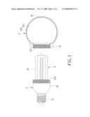
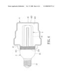
[0008]FIG. 1 is an exploded perspective view of the first preferred embodiment of a fluorescent lamp according to the present invention;
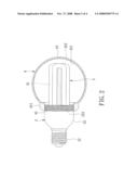
[0009]FIG. 2 is an assembled partly sectional view of the first preferred embodiment;
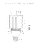
[0010]FIG. 3 is an assembled partly sectional view of the second preferred embodiment of a fluorescent lamp according to the present invention; and
[0011]FIG. 4 is an assembled partly sectional view of the third preferred embodiment of a fluorescent lamp according to the present invention.
DETAILED DESCRIPTION OF THE PREFERRED EMBODIMENTS
[0012]Before the present invention is described in greater detail with reference to the accompanying preferred embodiments, it should be noted herein that like elements are denoted by the same reference numerals throughout the disclosure.
[0013]Referring to FIGS. 1 and 2, the first preferred embodiment of a fluorescent lamp according to the present invention is shown to include: a UV light-generating unit including a lamp seat 2, a lamp vessel 3 sealed hermetically to the lamp seat 2 and defining a chamber 31 therein, and a luminous gas contained sealingly in the chamber 31 in the lamp vessel 3 for generating UV light when excited; and an outer vessel 4 mounted detachably on the lamp seat 2, enclosing the lamp vessel 3, and having an inner surface 422 coated with a UV-converting material 421.
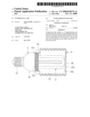
[0014]In this embodiment, the lamp seat 2 has a conductive base 21 and a case 22 opposite to the conductive base 21. The outer vessel 4 has a connecting end portion 41 connected detachably to the case 22 of the lamp seat 2, and a bulb portion 42 extending from the connecting end portion 41 of the outer vessel 4. The UV-converting material 421 is coated on the inner surface 422 of the bulb portion 42 of the outer vessel 4.
[0015]The case 22 of the lamp seat 2 has an outer threaded section 221. The connecting end portion 41 of the outer vessel 4 has an inner threaded section 411 that engages threadedly the outer threaded section 221 of the case 22.
[0016]The luminous gas includes a mercury-containing inert gas, such as Ar and Ne. The UV-converting material 421 is a phosphor material.
[0017]In use, the luminous gas in the chamber 31 in the lamp vessel 3 is excited to radiate UV light. The generated UV light passes through the lamp vessel 3 and into the outer vessel 4, and is converted into visible light through the UV-converting material 421.
[0018]Referring to FIGS. 3 and 4, the second and third preferred embodiments of the present invention differ from the previous preferred embodiment in that the outer vessels 4 of the second and third preferred embodiments have a different shape which is chosen based on actual requirements.
[0019]When the UV-converting material 421 deteriorates, only the outer vessel 4 is required to be replaced. Hence, the aforesaid drawback associated with the prior art can be eliminated.
[0020]While the present invention has been described in connection with what are considered the most practical and preferred embodiments, it is understood that this invention is not limited to the disclosed embodiments but is intended to cover various arrangements included within the spirit and scope of the broadest interpretation so as to encompass all such modifications and equivalent arrangements.
Claims:
1. A fluorescent lamp comprising:a UV light-generating unit includinga
lamp seat,a lamp vessel sealed hermetically to said lamp seat, anda
luminous gas contained sealingly in said lamp vessel for generating UV
light when excited; andan outer vessel mounted detachably on said lamp
seat, enclosing said lamp vessel, and having an inner surface coated with
a UV-converting material.
2. The fluorescent lamp as claimed in claim 1, wherein said lamp seat has a conductive base and a case opposite to said conductive base, said outer vessel having a connecting end portion connected detachably to said case of said lamp seat, and a bulb portion extending from said connecting end portion of said outer vessel, said UV-converting material being coated on said inner surface of said bulb portion of said outer vessel.
3. The fluorescent lamp as claimed in claim 2, wherein said case of said lamp seat and said connecting end portion of said outer vessel are threadedly engaged.
4. The fluorescent lamp as claimed in claim 1, wherein said luminous gas includes a mercury-containing inert gas.
5. The fluorescent lamp as claimed in claim 1, wherein said UV-converting material is a phosphor material.
Description:
BACKGROUND OF THE INVENTION
[0001]1. Field of the Invention
[0002]The invention relates to a fluorescent lamp, more particularly to a fluorescent lamp including a lamp vessel containing a luminous gas therein and an outer vessel enclosing the lamp vessel and coated with a phosphor material.
[0003]2. Description of the Related Art
[0004]U.S. Pat. No. 7,088,056 discloses a fluorescent lamp that includes a case, a base connected to the case, and a luminous bulb mounted sealingly on the case. The luminous bulb includes an inner tube that encloses an induction coil therein, and an outer tube sealed from the inner tube, containing a mercury-containing luminous gas therein, and coated with a phosphor layer on an inner surface thereof. The case, the base, the induction coil, and the luminous bulb are integrated into one unit. As such, when the phosphor layer deteriorates, the entire unit is required to be replaced.
SUMMARY OF THE INVENTION
[0005]Therefore, the object of the present invention is to provide a fluorescent lamp that can overcome the aforesaid drawback associated with the prior art.
[0006]Accordingly, a fluorescent lamp of the present invention comprises: a UV light-generating unit including a lamp seat, a lamp vessel sealed hermetically to the lamp seat, and a luminous gas contained sealingly in the lamp vessel for generating UV light when excited; and an outer vessel mounted detachably on the lamp seat, enclosing the lamp vessel, and having an inner surface coated with a UV-converting material.
BRIEF DESCRIPTION OF THE DRAWINGS
[0007]Other features and advantages of the present invention will become apparent in the following detailed description of the preferred embodiments with reference to the accompanying drawings, of which:
[0008]FIG. 1 is an exploded perspective view of the first preferred embodiment of a fluorescent lamp according to the present invention;
[0009]FIG. 2 is an assembled partly sectional view of the first preferred embodiment;
[0010]FIG. 3 is an assembled partly sectional view of the second preferred embodiment of a fluorescent lamp according to the present invention; and
[0011]FIG. 4 is an assembled partly sectional view of the third preferred embodiment of a fluorescent lamp according to the present invention.
DETAILED DESCRIPTION OF THE PREFERRED EMBODIMENTS
[0012]Before the present invention is described in greater detail with reference to the accompanying preferred embodiments, it should be noted herein that like elements are denoted by the same reference numerals throughout the disclosure.
[0013]Referring to FIGS. 1 and 2, the first preferred embodiment of a fluorescent lamp according to the present invention is shown to include: a UV light-generating unit including a lamp seat 2, a lamp vessel 3 sealed hermetically to the lamp seat 2 and defining a chamber 31 therein, and a luminous gas contained sealingly in the chamber 31 in the lamp vessel 3 for generating UV light when excited; and an outer vessel 4 mounted detachably on the lamp seat 2, enclosing the lamp vessel 3, and having an inner surface 422 coated with a UV-converting material 421.
[0014]In this embodiment, the lamp seat 2 has a conductive base 21 and a case 22 opposite to the conductive base 21. The outer vessel 4 has a connecting end portion 41 connected detachably to the case 22 of the lamp seat 2, and a bulb portion 42 extending from the connecting end portion 41 of the outer vessel 4. The UV-converting material 421 is coated on the inner surface 422 of the bulb portion 42 of the outer vessel 4.
[0015]The case 22 of the lamp seat 2 has an outer threaded section 221. The connecting end portion 41 of the outer vessel 4 has an inner threaded section 411 that engages threadedly the outer threaded section 221 of the case 22.
[0016]The luminous gas includes a mercury-containing inert gas, such as Ar and Ne. The UV-converting material 421 is a phosphor material.
[0017]In use, the luminous gas in the chamber 31 in the lamp vessel 3 is excited to radiate UV light. The generated UV light passes through the lamp vessel 3 and into the outer vessel 4, and is converted into visible light through the UV-converting material 421.
[0018]Referring to FIGS. 3 and 4, the second and third preferred embodiments of the present invention differ from the previous preferred embodiment in that the outer vessels 4 of the second and third preferred embodiments have a different shape which is chosen based on actual requirements.
[0019]When the UV-converting material 421 deteriorates, only the outer vessel 4 is required to be replaced. Hence, the aforesaid drawback associated with the prior art can be eliminated.
[0020]While the present invention has been described in connection with what are considered the most practical and preferred embodiments, it is understood that this invention is not limited to the disclosed embodiments but is intended to cover various arrangements included within the spirit and scope of the broadest interpretation so as to encompass all such modifications and equivalent arrangements.
User Contributions:
Comment about this patent or add new information about this topic:
Images included with this patent application:
 |  |
 |  |
 |
| Similar patent applications: | |
| Date | Title |
|---|---|
| 2008-10-30 | Fluorescent lamp |
| 2008-11-13 | Low wattage fluorescent lamp |
| 2008-11-20 | Compact fluorescent lamp |
| 2009-02-19 | Odor neutralizing fluorescent sunlamp |
| 2009-02-26 | Fluorescent lamp tube |
| New patent applications in this class: | |
| Date | Title |
|---|---|
| 2022-05-05 | A phosphor combination for a uv emitting device and a uv generating device utilizing such a phosphor combination |
| 2016-03-17 | Compositions and methods for modifying lumen maintenance characteristics of phosphor-containing coatings |
| 2015-12-31 | Phosphor, deep ultraviolet light-emitting device and phosphor production method |
| 2015-02-26 | Coating systems and fluorescent lamps provided therewith |
| 2014-07-10 | Illuminant and illuminant lamp comprising said illuminant |
| New patent applications from these inventors: | |
| Date | Title |
|---|---|
| 2022-01-13 | Abnormality detecting system for a solar power grid |
| Top Inventors for class "Electric lamp and discharge devices" | |
| Rank | Inventor's name |
|---|---|
| 1 | Satoshi Seo |
| 2 | Shou-Shan Fan |
| 3 | Nobuharu Ohsawa |
| 4 | Liang Liu |
| 5 | Peng Liu |