Patent application title: Heat Exchanger
Inventors:
Josef Bachmaier (Hohenpolding, DE)
IPC8 Class: AF28D702FI
USPC Class:
165164
Class name: Heat exchange flow passages for two confined fluids
Publication date: 2008-10-23
Patent application number: 20080257534
Inventors list |
Agents list |
Assignees list |
List by place |
Classification tree browser |
Top 100 Inventors |
Top 100 Agents |
Top 100 Assignees |
Usenet FAQ Index |
Documents |
Other FAQs |
Patent application title: Heat Exchanger
Inventors:
Josef Bachmaier
Agents:
BROOKS KUSHMAN P.C.
Assignees:
Origin: SOUTHFIELD, MI US
IPC8 Class: AF28D702FI
USPC Class:
165164
Abstract:
The invention relates to a heat exchanger provided with channels (3.1,
3.2) which are separated by separating walls, and which are cross-flown
in an alternating manner to the counter flow by one or the other flow
mediums (W, K). Said heat exchanger is formed by a spiral-shaped, wound,
sheet-like material (1). The windings (2.1, 2.2, . . . ) of the spiral
form the separating walls between the channels (3.1, 3.2, . . . ). The
channels (3.1, 3.2, . . . ) are also separated from each other by
separating webs (4.1, 4.2, . . . ) which are arranged between adjacent
windings (2.1, 2.2, . . . ).Claims:
1. Heat exchanger comprising channels (3.1, 3.2, . . . , 13.1, 13.2)
separated by means of separation walls, which are cross flown in an
alternating manner to the counter flow by the one or the other flow
medium (K, W), characterized by at least one spiral-shaped wound
sheet-like material (1, 10, 11), wherein the windings (2.1, 2.2, . . . )
of the spiral form the separating walls and the channels (3.1, 3.2, . . .
, 13.1, 13.2, 20.1, 20.2, 20.3, 21.1, 21.2, 21.3) are formed by the
distances between the individual windings (2.1, 2.2, . . . ).
2. Heat exchanger as claimed in claim 1, wherein the channels (3.1, 3.2, . . . ) are separated from one another by separation webs (4.1, 4.2, . . . ) between adjacent windings.
3. Heat exchanger as claimed in claim 1, characterized by at least one pair of spiral-shaped sheets (10, 11) wound at a spacing to each other, wherein the channel (13.1) or the channels (20.1, 20.1, 20.3) for the one flow medium (W, K) is formed by the distance between the two sheets (10, 11) of the pair, and the channel (13.2) or the channels (21.1, 21.2, 21.3) for the other flow medium (K, W) is formed by the distance between the windings of the sheet pair (10, 11).
4. Heat exchanger as claimed in claim 1, wherein the individual channels (3.1, 3.2, . . . ) at a front end (A, B) of the heat exchanger are closed through a partial circle (5.1, 5.2, . . . ) and are open at the other front end (B, A) through a partial circle (6.1, 6.2, . . . ).
5. Heat exchanger as claimed in claim 2, wherein the separation webs (4.1, 4.2, . . . ) extend in parallel to the polar axis (P) of the spiral.
6. Heat exchanger as claimed in claim 5, wherein the closed partial circle (5.1, 5.2, . . . ) of a channel (3.1, 3.2, . . . ) at the one front end (A, B) is opposed by an open partial circle (6.1, 6.2, . . . ) at the other front end (B, A).
7. Heat exchanger as claimed in claim 4, wherein the closed partial circle (5.1, 5.2, . . . ) and the open partial circles (6.1, 6.2, . . . ) are formed by a semi circle.
8. Heat exchanger as claimed in claim 2, wherein the separation webs (4.1, 4.2, . . . ) extend in a screw-shaped manner around the polar axis (P) of the spiral.
9. Heat exchanger as claimed in claim 1, wherein the separation webs (4.1, 4.2, . . . ) are arranged in a manner adjoining one another between the windings (2.1, 2.2, . . . ).
10. Heat exchanger as claimed in claim 1, wherein one single separation web (4.1, 4.2, . . . ) is arranged between two windings (2.1, 2.2, . . . ).
11. Heat exchanger as claimed in claim 1, wherein the windings (2.1, 2.2, . . . ) are connected to one another punctually (6).
12. Heat exchanger as claimed in claim 1, wherein the spiral-shaped wound, sheet-like material (1) encloses a bypass channel (9) in the center of the heat exchanger.
13. Heat exchanger as claimed in claim 3, wherein the two sheets (10, 11) of each pair are connected to one another according to a first predetermined angle (a) and the inner sheet (11) of a winding to the outer sheet (10) of the adjoining inner winding according to a second predetermined angle (b), which is offset with respect to the first predetermined angle (a), to form the channels (20.1, 20.2, 20.3) for the one flow medium (K) and the channels (21.1, 21.2, 21.3) for the other flow medium (Wk).
14. Heat exchanger as claimed in claim 13, wherein the first angle (a) and the second angle (b) are equally large.
15. Heat exchanger as claimed in claim 13, wherein the angle about which the connections (24) between the inner sheet (11) of a winding with the outer sheet (10) of the respective inner winding are offset with respect to the connections of the two sheets (10, 11) of each pair is half of the first angle (a).
16. Heat exchanger as claimed in claim 13, wherein the connections between the sheet pairs (10, 11) are formed by constrictions (23) of the sheet pairs.
17. Heat exchanger as claimed in claim 13, wherein the channels (20.1, 20.2, 20.3) for the one flow medium (K) and the channels (21.1, 21.2, 21.3) for the other flow medium (Wk) to the polar axis (P) are arranged radially behind one another.
Description:
[0001]The present invention refers to a heat exchanger according to the
preamble of claim 1.
[0002]The most different types of heat exchangers are known, e.g. tubular heat exchangers, plate heat exchangers, etc. They do not only differ in type, they also differ in their field of application. Heat exchangers are for instance used for air ventilation of rooms, however, they are also used in Stirling machines or nitrogen motors. Besides the high efficiency and a low manufacturing effort, a low space requirement and a high compressive and/or heat resistance is required.
[0003]It is the object of the present invention to provide a heat exchanger that fulfills these requirements.
[0004]This is achieved according to the invention by the heat exchanger characterized in claim 1. Advantageous developments of the invention are defined in the dependent claims.
[0005]According to the invention the heat exchanger is manufactured in a simple manner in that at least one sheet-like material is wound around the longitudinal axis of the heat exchanger. Seen in cross section, a spiral with spaced apart windings is formed thereby. The windings therefore form the separating walls, while the channels are formed through the space between the spaced apart windings. In order to separate the individual channels from one another, additional separation webs may be provided between adjacent windings, said webs extending along the heat exchanger from one front end to the other front end. Thus, one channel each is formed between two windings and two separation webs. This ensures a compact, space-saving structure of the heat exchanger according to the invention. Moreover, the heat exchanger may be produced as yard ware with any amount of windings and with any dimension.
[0006]The channels are cross-flown in an alternating manner to the counter flow by one or the other flow medium between which the heat transfer takes place. That means that the innermost or first channel between the innermost or first winding and the second winding is cross flown by a for instance warm flow medium in one direction and the second channel between the second winding and the third winding is cross flown by the other, colder flow medium in the counter direction, the third channel is cross flown by the warm flow medium and so forth.
[0007]The flow medium may both be a gas as well as a liquid, but also a solid heat storage mass having a melting temperature below the temperature of the warm flow medium, e.g. paraffin, wax or grease. The sheet-like material may be metal, plastics or a different material, if it can be wound or if it can be produced in wound form. In a gaseous flow medium and less extreme demands, e.g. when being used for ventilating rooms, the sheet-like material may be plastics. In the case of high temperatures a stainless steel sheet can also be used.
[0008]Particularly if the separation walls are integrally formed of a sheet-like material, the heat exchanger according to the invention has a high compressive strength and temperature resistance. To increase the compressive strength, punctual joints ma be provided between the windings preferably in the longitudinal direction and distributed around the circumference.
[0009]To prolong the flow path at an identical length and identical diameter of the heat exchanger and to thereby increase the efficiency, the individual channels are preferably closed at the front ends of the heat exchanger via a partial circle and at the other front ends they are open via a partial circle. If the separation webs extend in parallel with respect to the polar axis of the spiral, i.e. in parallel with respect to the longitudinal axis of the heat exchanger, the closed partial circle of a channel at the one front end is preferably opposed by an open partial circle on the other front end. Thus, the flow medium does not flow straightly through the channels but is deflected in the circumferential direction so that it exits at the other front end referring to the cross section of the heat exchanger on the opposite side. That means if it enters at a horizontally arranged heat exchanger at the top of the one front end or on the right side into the channel, it exits at the other front end on the bottom or left side.
[0010]The partial circles are preferably formed by semi circles. The open partial circles or semi circles through which the flow medium enters into the heat exchanger, are preferably arranged on the same side or half of the one side of the heat exchanger, and the open partial circles or semi circles through which the other flow medium enters on the other front end in the counter direction are arranged on the opposite side or half of the other front end.
[0011]That means that in the case of a horizontally arranged heat exchanger and separation webs extending in parallel to the longitudinal axis, the open partial or semi circles are provided e.g. on the bottom or right side for entry of the one flow medium, and the open partial or semi circles at the other front end are provided for entry of the other flow medium in the counter flow on the top or left. Thus, connection of the heat exchanger is significantly facilitated, since the one flow medium can be connected at the one front end and the other flow medium can be connected in counter flow on the other front end on a side or half of the respective front end.
[0012]The separation webs may extend spirally around the polar axis of the spiral, i.e. the longitudinal axis of the heat exchanger. The screw angle may be 180° or a multiple thereof. Thus, the flow medium may enter at the same side at the one front end and it may exist at the other front end, i.e. it may enter in a horizontally arranged heat exchanger in the upper half at the front end and it may exit from the other front end at the upper half.
[0013]The heat exchanger according to the invention may be used in different fields. It may for instance be used in nitrogen motors in which liquid nitrogen is relieved with air, i.e. in which the nitrogen forms the cold flow medium and air or water in the counter flow form the warm flow medium. As a further alternative of use the Stirling machine must be cited, since the heat exchanger according to the invention can withstand a high pressure and a high temperature. The heat exchanger according to the invention may also be used as an absorber for heat pumps, furthermore as water/air heater, e.g. as a pre-heater or re-heater. It is also excellently suitable for geo-heat systems.
[0014]If an electrical contact is arranged at the one and the other side of each winding, the heat exchanger according to the invention can also be used for producing thermal current according to the Peltier effect.
[0015]Three embodiments of the heat exchanger according to the invention are explained in detail by means of the enclosed drawing. The Figures schematically show:
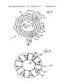
[0016]FIG. 1 shows a heat exchanger according to a first embodiment in perspective view;
[0017]FIGS. 2 and 3 show a top plan view onto the one or the other front end of the heat exchanger;
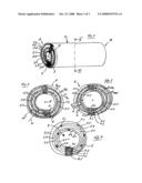
[0018]FIG. 4 shows a cross section along line IV-IV in FIG. 1;
[0019]FIG. 5 shows a cross section through the heat exchanger according to a further embodiment;
[0020]FIGS. 6 and 7 show a top plan view onto a front end of the heat exchanger with a lid and without a lid according to FIG. 5;
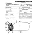
[0021]FIG. 8 show a top plan view corresponding to FIG. 7, however, onto a heat exchanger formed as a mixer;
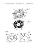
[0022]FIG. 9 shows a cross section through the heat exchanger according to a third embodiment; and
[0023]FIG. 10 show a top plan view onto a front end of the heat exchanger according to FIG. 9 with the lid for one of the two flow media.
[0024]The heat exchanger according to the invention is composed of a sheet-like material 1, which is helically wound around the longitudinal axis of the heat exchanger or polar axis P of the spiral. The windings 2.1, 2.2, 2.3, . . . , 2.6 of the spiral form the separation walls of the heat exchanger, whereas channels 3.1, 3.2, . . . 3.5 are formed by the space between the adjacent windings.
[0025]In order to separate the individual channels from one another in a flow medium-tight manner, additional separation webs 4.1, 4.2, . . . , 4.5 are provided between adjacent windings 2.1, 2.2, 2.3, . . . , extending along the heat exchanger from a front end A to the other front end B.
[0026]The channels 3.1, 3.2, . . . are cross flown in an alternating manner to the counter flow by the warm flow medium W and the cold flow medium K, respectively, wherein the warm flow medium W enters at the front end A and exits at the other front end B as Wk, while the cold flow medium K enters at the front end B and exists in heated manner at the front end A as Kw.
[0027]That means that the innermost or first channel 3.1. between the innermost or first winding 2.1 and the second winding 2.2 is cross flown by the cold flow medium K in the one direction and the second channel 3.2 between the winding 2.2 and the third winding 2.3 is cross flown by the warm flow medium W in the counter direction, the third channel 3.3 is again cross flown by the cold flow medium K, the fourth channel 3.4 is cross flown by the warm flow medium W and the fifth channel 3.5 is cross flown by the cold flow medium K.
[0028]To prolong the flow path and to thereby increase efficiency, the individual channels 3.1, 3.2, . . . are closed at both front ends A and B of the heat exchanger through a semi circle 5.1, 5.2, . . . 5.5 and are open inbetween. The closed semi circle 5.1, 5.2, on the one front end A is opposed by an open semi circle 6.1, 6.2, . . . on the other front end B. The closed semi circles 5.1, 5.2, extend up to the separation web 4.1, 4.2, . . . . Since the separation webs 4.1, 4.2, . . . extend in parallel to the polar axis P, the flow medium W and K, respectively, does not straightly flow through the channels 3.1, 3.2, . . . , but it is deflected in the circumferential direction, so that it exits on the opposite half. That means the flow medium W enters at the one, left half of the front end A and exits on the other opposite, i.e. right half of the front end B as Wk, while the other flow medium K enters at the left half of the front end B and exits at the right half of the front end A as Kw, so that the respective inlet and outlet lines can be connected there.
[0029]To increase the compressive strength of the heat exchanger, punctual joints 6' are provided between the windings 2.1, 2.2, . . . distributed in the longitudinal direction and in the circumferential direction, said joints being produced e.g. by spot welding.
[0030]The separation webs 4.1, 4.2, . . . between the individual windings 2.1, 2.2 are arranged in a manner adjoining one another on one side of the heat exchanger. The end sections of the inner and outer longitudinal edge 7 and 8, respectively of the spirally wound material 1 is tightly connected to the adjoining winding 2.2 and 2.5, respectively.
[0031]A bypass channel 9 is provided in the center of the heat exchanger, through which when the heat exchanger is used for ventilating rooms cold air can be conveyed into the room, for instance during summer time.
[0032]To improve the heat transition, lamellae or similar elements enlarging surfaces can be provided in the channels 3.1, 3.2 . . . .
[0033]In the further embodiment of the heat exchanger according to FIGS. 5 and 6, two, i.e. a pair of sheets 10 and 11 separated from one another by means of spacers 14 are spirally wound around the longitudinal or polar axis P. The channel 13.1 for the one, e.g. the warm flow medium W is formed by the distance between the two sheets 10 and 11, and the channel 13.2 for the other, e.g. the cold flow medium K, is formed by the distance between the inner sheet 11 of the respective outer winding of the sheet pair 11, 12 and the outer sheet 10 of the adjoining inner winding of the sheet pair 10, 11.
[0034]Screw-shaped separation webs may for instance be provided in the channels 13.1 and 13.2 (not shown) in order to prolong the flow path. The channels 13.1 and 13.2 can have a different width caused by differently long spacers 15. A broad channel 13.2 for the air passage and a small channel 13.1 for the water passage may for instance be provided in an air/heat exchanger.
[0035]FIG. 5 also shows the contacts 15, 16 for collecting the thermal current according to the Peltier effect from the sheet 11, which is heated on the one side by the warm flow medium W in the channel 13.1 and which is cooled on the other side by the cold flow medium K in the channel 13.2.
[0036]The heat exchanger according to the invention may also be adapted for three and more media. If for instance a separation web is provided in the of the channels 13.1, 13.2, to form three channels, the heat carrier liquid heated by a solar plant may for instance flow through a channel, a heat storage mass may be provided in the second channel, e.g. paraffin or grease, and for instance water may flow through the third channel in the passage to obtain hot water.
[0037]According to FIG. 6 the channel 13.1 in the embodiment according to FIG. 5 may be closed at a front end on one, e.g. the left-hand side, and it may be open on the other side, whereas the channel 13.2 on this front end is open on the left-hand side and is closed on the right-hand side. By attaching respective lids 17, 18 with pipe connections 19, 20 on the respective side of each front end, the respective inlet and outlet lines for the respective flow medium can be connected. The bypass channel 6 is closed by the lid.
[0038]If the bypass channel 6 is connected to the channel 13.1 and/or 13.2, the heat exchanger may also be used as a mixer. As shown in FIG. 8, the lid 18 from which the warmer flow medium exits, also extends over the bypass channel 16.
[0039]The embodiment according to FIGS. 9 and 10 differs from the embodiment according to FIG. 5 substantially in that the two sheets 10, 11 of each pair are connected to one another according to a first predetermined angle α, and the inner sheet 11 of a winding is connected to the outer sheet 10 of the adjoining inner winding according to a second predetermined angle β, which is offset with respect to the first predetermined angle α to form the channels 20.1, 20.2, 20.3 for the one flow medium and 21.1, 21.2 and 21.3 for the other flow medium.
[0040]The connections between the sheets 10, 11 of a pair are formed by constrictions 23 of the sheet pairs.
[0041]The angle about which the constrictions 23 are offset with respect to the connections 24 between the inner sheet 11 of a winding with the outer sheet 10 of the respective adjoining inner winding is α/2. In this manner the channels 20.1, 20.2 and 20.3 for the for instance cold flow medium K, and the channels 21.1, 21.2, 21.3 for the warm flow medium Wk are arranged radially behind one another. Compared to the embodiment according to FIG. 5 the heat exchanger surface is enlarged in this embodiment.
[0042]FIG. 10 schematically shows the lid 26, which locks the channels 21.1, 21.2, 21.3 at a front end of the heat exchanger to connect these channels with the outlet line for the flow medium Wk. The lid 26 comprises radially extending wings 27 which cover the channels 21.1, 21.2 and 21.3. The gussets 28 at the constrictions 23 and connections 24 are closed to separate the two flow media from one another. The lid that is not shown on this front end for connecting the inlet line for the cold flow medium K with the heat exchanger 1 is structured identically as the lid 26.
[0043]In the embodiments according to FIG. 1 to 4 and 5 to 8 the inlet and outlet of the flow media at the two front ends of the heat exchanger 1 may also be implemented in several partial circles, i.e. not only in the shape of semi circles, as shown in FIG. 1 to 4, and 5 to 8, respectively.
[0044]Thus, it is e.g. possible to provide two partial circles with 90° with respect to the entry and two partial circles with 90° with respect to the exit, or six partial circles with 30° with respect to the entry and six partial circles with 30° with respect to the outlet, or four partial circles with 60° with respect to the entry and two partial circles with 60° with respect to the exit, or two partial circles with 160° with respect to the entry and two partial circles with 20° with respect to the exit on each front end of the heat exchanger.
[0045]In the case of gases and high temperatures the inlet and outlet openings may be adapted to the volume changes by the cooling or heating through the size of the opening angles of the individual partial circles to the inlet and outlet volumes. That means that if a gas of a high temperature enters through a partial circle surface of e.g. 60% or an overall portion of the partial circle of e.g. 60% at a front end, the volume is reduced caused by the cooling effect and it exits at the other front end of the heat exchanger with e.g. 40% of the opening surface. In the same manner, e.g. 40% of the overall surface for the cold gas may be provided for the entry at one front end and e.g. 60% of the overall surface can be provided for the exit at the other front end of the heat exchanger.
[0046]A preferred application of this variant of the heat exchanger is the exhaust gas heat recovery, for instance in bio mass combustion in which the exhaust gas heats the combustion air.
[0047]According to the invention highly efficient ventilation heat exchangers can be manufactured at a low price. In this case, the bypass 6 in the interior is advantageous, particularly in connection with a mixing valve.
User Contributions:
comments("1"); ?> comment_form("1"); ?>Inventors list |
Agents list |
Assignees list |
List by place |
Classification tree browser |
Top 100 Inventors |
Top 100 Agents |
Top 100 Assignees |
Usenet FAQ Index |
Documents |
Other FAQs |
User Contributions:
Comment about this patent or add new information about this topic:
Images included with this patent application:
 |  |
 |  |
| Similar patent applications: | |
| Date | Title |
|---|---|
| 2010-08-26 | Sludge heat exchanger |
| 2010-08-26 | Heat exchanger |
| 2010-09-02 | Heat exchange surface |
| 2010-09-09 | Heat exchanger |
| 2010-09-09 | Heat exchanger |
| New patent applications in this class: | |
| Date | Title |
|---|---|
| 2016-05-12 | Heat exchanger |
| 2016-04-21 | Method for producing a heat exchanger module having at least two fluid flow circuits |
| 2016-03-17 | Manifold for process variable transmitter with steam coupling |
| 2016-02-25 | High effectiveness low pressure drop heat exchanger |
| 2016-01-07 | Countercurrent heat exchanger/reactor |
| Top Inventors for class "Heat exchange" | |
| Rank | Inventor's name |
|---|---|
| 1 | Levi A. Campbell |
| 2 | Chun-Chi Chen |
| 3 | Tai-Her Yang |
| 4 | Robert E. Simons |
| 5 | Richard C. Chu |