Patent application title: Three Pipe System
Inventors:
Aristidis Afentoulidis (Kozani, GR)
IPC8 Class: AF28F110FI
USPC Class:
165172
Class name: Heat exchange side-by-side tubular structures or tube sections
Publication date: 2008-10-16
Patent application number: 20080251244
Inventors list |
Agents list |
Assignees list |
List by place |
Classification tree browser |
Top 100 Inventors |
Top 100 Agents |
Top 100 Assignees |
Usenet FAQ Index |
Documents |
Other FAQs |
Patent application title: Three Pipe System
Inventors:
Aristidis Afentoulidis
Agents:
JEROME D. JACKSON (JACKSON PATENT LAW OFFICE)
Assignees:
Origin: ALEXANDRIA, VA US
IPC8 Class: AF28F110FI
USPC Class:
165172
Abstract:
The 3-pipe system is a new method of building closed hydraulic networks
for heat transfer and fluid distribution. Generally, the new system can
be applied in HVAC networks and ensures better and more stable network
behaviour during flow adjustment. In other words, it ensures
hydraulically balanced networks with optimal behaviour. The basic
characteristic of the new three-pipe system is that the central
distribution pipe is split into two, in which water flows in the same
direction as in the central distribution pipe. Subsequently, the two
pipes are joined in one, which is the return pipe. Thus, the pipes create
a central loop, which includes the terminal units. The one part of the
loop is the point where the terminal unit branches start and the other is
where they end. Water flow is ensured by means of a local circulator,
which compensates for pressure drop in the branch. In case of reverse
flow in deactivated terminal units, a non-return valve is recommended for
each terminal unit. The structure of the patent is demonstrated in FIG.
<8>. The central distribution pipe <<A>> is split into
two pipes, <<B>> and <<C>>, in which water flow
is also split. The two pipes are joined again in pipe <<D>>,
creating a closed loop. Water in pipes <<A>>,
<<B>>, <<C>> and <<D>> flows in the
same direction. The terminal unit branches are positioned inside the
loop. Each local branch has got a circulator to compensate for water
supply. There is also a central circulator, which supplies the central
loop with water.Claims:
1. Structure of a closed HVAC network, which is characterised by a central
loop created by a distribution pipe which is split into two pipes and
joined in one again. Water in the distribution pipe, the split pipes and
the pipe joined in one flows in the same direction. The terminal unit
branches are positioned inside the central loop. In other words, the
terminal unit branches start at the one split pipe and end at the other.
When water flows in the central loop, there is no initial flow tendency
through the terminal unit branches. Thus, water flow in the local
branches requires a local circulator. Water flow in the central loop
should be regulated by means of a suitable circulator.
2. Structure as in <1>; the only difference is that the central distribution pipe is split into more than two pipes. One pipe is chosen as a network component where the return pipes of the local branches end whereas the rest of the pipes are used as a component where the distribution of local supply branches start.
3. Structure as in <1>; the only difference is that the central distribution pipe is split into more than two pipes. One pipe is chosen as a network component where the supply pipes of the local branches start whereas the rest of the pipes are used as a component where the local return branches end.
4. Structure as in <1>, composed of multiple central loops in series.
5. Structure as in <1>, composed of multiple central loops in parallel.
Description:
THEORETICAL CONSIDERATIONS
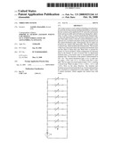
[0001]In HVAC systems, heat transfer is achieved by building closed hydraulic networks, in which the heating medium--usually water--flows. The water flows through pumps or circulators, which lend water with energy that compensates for friction loss in the network. Network building methodologies are plenty. All networks are comprised of a central distribution pipe and a central return pipe. The water flows through the central pipe of distribution, supplies the terminal units through the local distribution risers and branches, enters the local return pipes and, finally, the central return pipe and ends at the point it started. Conventional network structures are demonstrated in FIGS. <1>, <2>, <3>, <4> and <5>.
[0002]To facilitate understanding, it is emphasized that in FIG. 1, object 1 is a circulator and object 2 is a two-way control valve. In FIG. 3, object 3 is a non-return valve and object 4 indicates the flow direction. The specific objects are depicted in all Figures according to the illustrated example.
[0003]In all networks, the initial distribution temperature is common for all terminal units. There are special cases, however, for which the temperature in the central distribution pipe is variable during water flow, and, therefore, in each terminal unit, temperature is decreased (heating) or increased (cooling) (FIG. 6). The specific structure is common, but not widely used.
[0004]Notably, the above applications, which are conventional structures in a number of versions, are comprised of 3-way or 4-way control valves, additional circulators apart from the basic ones, a pressure break bottle, and self regulating valves, which do not spoil the fundamental and original structure and network building methodology.
[0005]The structure demonstrated in FIG. <1> is the most common type and is widely used. A simple form of such a structure has got a central circulator for water flow, but in extended networks there can be more circulators for energy distribution.
[0006]The structure demonstrated in FIG. <2> has got one circulator for each terminal unit and after each circulator there is a non-return valve to cut off any undesirable reverse flow.
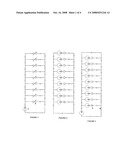
[0007]Frequently, structures like that in FIG. <2> include a central circulator (FIG. <3>, with or without a bypass pipe), whereas structures similar to those in FIG. <3> are often used as collectors of low pressure drop and provide for terminal unit hydraulic independence. Apart from the non-return valve above the circulators, it is likely that a 2-way on-off valve be used so that undesirable flow could be cut off. The structure demonstrated in FIG. <4> (also called Tichelmann structure), is similar to that in FIG. <1>, but the only difference is that each local branch is composed of equal sized pipes. The structure demonstrated in FIG. <5> is a Tichelmann structure with circulators per branch, whereas the structure in FIG. <6> is a special structure, which is not commonly used due to the fact that the distribution temperature in the local branches is variable. In the specific structure, the central distribution pipe is also used as a central return pipe.
[0008]In all structures discussed above, especially in the basic types, there are interference and interactive phenomena; in other words, adjusting or cutting off a branch can lead to flow variation and ΔP (pressure drop) in the rest of branches, which is different for different types of networks and depends on network sizing. Interactive phenomena in the branches are critical and bring about various problems related to network operation, heating or cooling failure per terminal unit, energy waste and, in general terms, network deterioration.
[0009]The specific problems can be partly eliminated by using self regulating valves, pressure break bottles and 3-way or 4-way valves, depending on the case.
REFERENCES
[0010]1. Recknagel Sprenger Schramek, Taschenbuch fuer Heizung und Klimatechnik 94/95 [0011]2. Robert Petitjean, Total Hydronic Balancing [0012]3. H. Roos, Hydraulik der Wasserheizung. 2A [0013]4. W. Burkhardt, Projektierung von Warmwasserheizungen [0014]5. Trainings & Weiterbildungszentrum Wolfenbueteel e.V. (enev.tww.de) [0015]6. Internetsite (hydronicpros.com) by John Siegenthaler [0016]7. ASHRAE Handbook
THE PATENT
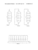
[0017]The structure suggested consists of a central distribution pipe which is split into two pipes and after that joined again in one pipe, so as to create a central closed loop where the local terminal units are connected.
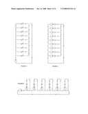
[0018]In detail, the local terminal units are distributed through the one side of the split central distribution pipe and the water from each local branch returns to the other side of the split central pipe. The structure of the application suggested is depicted in FIG. <7>. The central distribution pipe <<A>> is split in two pipes, pipes <<B>> and <<C>>. In the specific pipes, water flow is also split. The two pipes, <<B>> and <<C>>, are joined again in one pipe, pipe <<D>>, and creates a closed loop. Water in pipes <<A>>, <<B>>, <<C>> and <<D>> flows in the same direction. The terminal unit branches are connected to the loop. Each local branch has a circulator to compensate for water distribution. During operation, when all terminal units are deactivated, water flow is split in branches <<B>> and <<C>> and does not enter any terminal unit branches. When one terminal unit is activated, water flow in branch "B" is increased by the rate of flow in the activated terminal unit and in branch "C" it is reduced by the same rate. At the point after the terminal unit, the opposite procedure takes place in the two branches, and consequently the water flow in branch "B" is reduced by the rate of flow in the activated terminal unit and in branch "C" it is increased at the same rate.
[0019]The more terminal units are activated, the more the quantity of water that enters branch <<B>> and the less that enters branch <<C>>.
[0020]On the contrary, at the end of the loop, water flow is increased in branch <<C>> and reduced in branch <<B>>.
[0021]Notably, water flow in the terminal unit loop requires the use of a central circulator, as demonstrated in FIG. <8>.
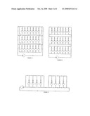
[0022]In case of reverse flow in deactivated terminal units, a non-return valve is recommended for each terminal unit, FIG. <9>.
[0023]In FIG. <10>, there is the structure of a simple application of the system. The Figure demonstrates the division of the central pipe, the terminal unit loop, the use of the one part of the loop for the local distribution pipes, and of the other part for the point where local return pipes end. FIGS. <11>, <12> and <13> demonstrate some other more complex applications of the three-pipe system.
[0024]In general terms, the system is characterized by symmetry, harmony and balance during operation. It is also particularly stable and hydraulically independent, and, compared with all existing similar systems, interference and interactive phenomena in the network, under similar conditions of operation, are significantly fewer and, in effect, negligible. This is an essential advantage in terms of operation, reliability and energy saving. The specific structure can be applied to any HVAC system, that is, in every hydraulic closed network of heat transfer, such as in home central heating units, district heating, and hotel or building air conditioning systems with water coolers.
User Contributions:
comments("1"); ?> comment_form("1"); ?>Inventors list |
Agents list |
Assignees list |
List by place |
Classification tree browser |
Top 100 Inventors |
Top 100 Agents |
Top 100 Assignees |
Usenet FAQ Index |
Documents |
Other FAQs |
User Contributions:
Comment about this patent or add new information about this topic:
| People who visited this patent also read: | |
| Patent application number | Title |
|---|---|
| 20120020053 | PACKAGE, LIGHT UNIFORMIZATION STRUCTURE, AND BACKLIGHT MODULE USING SAME |
| 20120020052 | FLAMELESS CANDLE WITH FRAGRANCE DIFFUSION |
| 20120020051 | ILLUMINATION SYSTEM WITH REMOTE PHOSPHOR LAYER AND/OR SCATTERING LAYER |
| 20120020050 | Chemiluminescent grenade |
| 20120020049 | HOOK-TYPE ELECTRIC METER CAPABLE OF PROVIDING LIGHT SOURCE |
Images included with this patent application:
 |  |
 |  |
 |
| New patent applications in this class: | |
| Date | Title |
|---|---|
| 2019-05-16 | Heat exchanger with louvered fins |
| 2016-06-02 | Heat exchanger, air-conditioning apparatus using the same and method of manufacturing the same |
| 2016-05-05 | Waste heat reclamation system, method for reclamation of waste heat, and system and method for using waste heat |
| 2016-04-28 | Aerodynamic tube shields |
| 2016-03-10 | Hygienic heat exchanger |
| Top Inventors for class "Heat exchange" | |
| Rank | Inventor's name |
|---|---|
| 1 | Levi A. Campbell |
| 2 | Chun-Chi Chen |
| 3 | Tai-Her Yang |
| 4 | Robert E. Simons |
| 5 | Richard C. Chu |