Patent application title: Tile grouting machine
Inventors:
Robert Brasier (Nashville, TN, US)
IPC8 Class: AE04F21165FI
USPC Class:
425 87
Class name: Plastic article or earthenware shaping or treating: apparatus hand movable, substrate traversing, plural dimension shaping means including molding material supply
Publication date: 2008-10-02
Patent application number: 20080241294
Inventors list |
Agents list |
Assignees list |
List by place |
Classification tree browser |
Top 100 Inventors |
Top 100 Agents |
Top 100 Assignees |
Usenet FAQ Index |
Documents |
Other FAQs |
Patent application title: Tile grouting machine
Inventors:
Robert Brasier
Agents:
JAMES RAY & ASSOCIATES
Assignees:
Origin: MONROEVILLE, PA US
IPC8 Class: AE04F21165FI
USPC Class:
425 87
Abstract:
A tile grouting machine has an electric motor mounted in a housing. At one
end of the housing is a rubber boot having an outer edge and a back wall
so as to form a cavity to receive grout. A drive connects the shaft of
the motor to the boot and the drive includes a cam for shaking the boot
in a direction parallel to the plane defined by the open end of the boot.Claims:
1. A tile grouting machine comprisingan electric motor,a boot having an
outer edge defining a plane and a cavity behind said outer edge, anda
drive between said motor and said boot wherein said motor and said drive
will shake said boot causing movement perpendicular to said plane.
2. The tile grouting machine of claim 1 wherein said drive includes a cam.
3. The tile grouting machine of claim 1 and further comprisinga housing,a motor mounted on and said housing, anda retaining member moveably retaining said boot to said housing.
4. The tile grouting machine of claim 3 wherein said drive includes a cam for causing a shaking movement of said foot.
Description:
[0001]The applicant claims priority from his provisional application filed
Mar. 28, 2007 and assigned Ser. No. 60/908,440. The present invention
relates to the grouting industry and to a machine to assist in the
applying of grout.
BACKGROUND OF THE INVENTION
[0002]Tile setters apply tiles to a surface, such as a wall or floor, and fill the spaced between adjacent tiles with a grout. Tiling provides a decorative surface and therefore a tile setter spends a great deal of his time in the application of grout to ensure that the grout fills all the spaces between the tiles and is compacted therein to provide an attractive appearance that will last the life of the tile. Prior to the present invention, a tile setter must use a trowel and manually force the grout into the crevices between adjacent tiles.
SUMMARY OF THE INVENTION
[0003]Briefly, the present invention is a tile grouting machine that includes an electric motor and a boot having an outer edge that defines a plane and a cavity within the boot rearward of the outer edge. A drive connects the motor to the boot to shake the boot by causing movement perpendicular to the plane of the outer edge of the boot.
BRIEF DESCRIPTION OF THE DRAWINGS
[0004]A better and more complete understanding of the invention can be had after a reading of the following detailed description taken in conjunction with the drawings wherein:
[0005]FIG. 1 is a side elevational view of a grouting machine in accordance with the present invention;
[0006]FIG. 2 is an isometric view of the bottom of the boot and drive of the machine shown in FIG. 1;
[0007]FIG. 3 is a cross-sectional view of the boot and drive taken through line 3-3 of FIG. 1; and
[0008]FIG. 4 is a cross-sectional view of the drive for the machine taken through line 4-4 of FIG. 1.
DETAILED DESCRIPTION OF PREFERRED EMBODIMENT
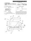
[0009]Referring to FIG. 1, a tile grouting machine 10 includes an electric motor 12 having a power cord 14 with a suitable connector 16 at the distal end thereof for connecting to a source of AC power to thereby apply power to the windings of the motor. The machine 10 also includes a switch 18 one pole of which is connected to one of the connectors 16 and the other of which is connected to the motor 12 such that opening the switch 18 terminates power to the motor 12 and closing the switch 18 applies power to the motor 12 when the connector 16 is connected to a source of AC power.
[0010]The invention may also include an adjustable control 20 for selectively applying power received through the connector 16 to the motor 12 to thereby adjust the speed of the motor 12.
[0011]The motor 12 is mounted in a housing 22 which may be made of a non-electrically conductive plastic. Alternately, the housing 22 may be made of a metal with the portions of the electric motor 12 that are exposed to the source of electric power insulated from the housing 22. The housing 22 includes a handle 24 suitably shaped to be grasped by the human hand to thereby enable a tile setter to control the device as it assists in the compacting of grout between adjacent tiles.
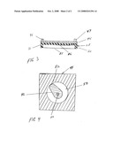
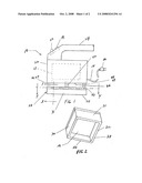
[0012]The machine 10 also includes a working end 26 adequately spaced from the handle 22 so as to protect the operator's hands during operation of the device. Although the device 10 can be used to apply grout between tiles whether they are attached to a floor, a wall, or ceiling, for the purposes of this discussion the working end 26 of the machine will be described as the forward end and therefore the motor 12 is herein described as being rearward of the working end 26. Accordingly, forward of the working end 26 is a boot 28 that is preferably made of a relatively stiff rubber. The boot 28 is generally rectangular in shape having sides 30, 31, 32, 33 and rearward of the sides a generally planar back 36. The forward edge 38 of the sides 30-33 define a plane generally parallel to the back 36 and the inner surfaces of the sides 30-33 and the back 38 defining a cavity behind the plane defined by the forward edge 38.
[0013]As best shown in FIG. 4, the motor 12 drives an output shaft 40 upon which is mounted a non-circular cam 42. The cam 42 is received in a generally cylindrical retainer 44 which is bonded by a glue or other suitable means to the back 36 of the boot 28. Also, a plurality of flexible pegs 46, 47, 48, 49 have one end connected to the housing 22 and the other end thereof connected to the boot 28 to generally retain the boot 28 a fixed distance from the housing 22 but allowing for a small amount of movement of the boot in a direction parallel to the plane define by the outer edge 38.
[0014]As best seen in FIG. 4, the retainer 44 has a cylindrical aperture 50 that is positioned to be coaxial with the shaft 40 and having a diameter a little larger than the diameter of the cam 42 such that the cam 42 is rotatable within the aperture 50. The cam 42, however, has an elongated cam end 52 the length of which is a little longer than the radius of the aperture 50 such that rotation of the shaft 40 and the cam 42 causes movement of the retainer 44 and the boot 28 in a direction parallel to the plane defined by the forward edge 38.
[0015]To use the machine 10 to apply grout between adjacent tiles, a quantity of grout is applied into the cavity of the boot 28 with a trowel or other tool. The connector 16 of the power cord 14 is inserted into a suitable receptacle for receiving AC power and the open end of the boot 28 is applied against the surface of the tile. The switch 18 is then turned to the on position causing the motor 12 to rotate the cam 42 and shake the boot 28. The flexible pegs 46-49 bend in response to movement of the boot 28 allowing the boot 28 to vibrate without damaging the pegs 46-49. The machine 10 is then moved over the surface of the tiles causing the grout in the boot to be urged between the tiles and compacted.
[0016]While the present invention has been described with respect to a single embodiment, it will be appreciated that many modifications and variations may be made without departing from the true spirit and scope of the invention. It is therefore the intent of the appended claims to cover all such modifications and variations that fall within the spirit and scope of the invention.
User Contributions:
comments("1"); ?> comment_form("1"); ?>Inventors list |
Agents list |
Assignees list |
List by place |
Classification tree browser |
Top 100 Inventors |
Top 100 Agents |
Top 100 Assignees |
Usenet FAQ Index |
Documents |
Other FAQs |
User Contributions:
Comment about this patent or add new information about this topic:
| People who visited this patent also read: | |
| Patent application number | Title |
|---|---|
| 20150229600 | Method, Apparatus, And System For Automatically Prompting User To Sign Up For Microblog |
| 20150229599 | METHODS AND SYSTEMS FOR SHARING EMAIL IN A MULTITENANT DATABASE SYSTEM |
| 20150229598 | METHOD AND SYSTEM OF SYNCHRONING AN UNREAD MESSAGE IN INSTANT COMMUNICATION |
| 20150229597 | METHODS FOR OBTAINING A NAVIGATION TRACK BETWEEN A FIRST AND A SECOND LOCATION AT A CLIENT DEVICE USING LOCATION INFORMATION OBTAINED FROM A SERVER DEVICE AND RELATED DEVICES AND COMPUTER PROGRAM PRODUCTS |
| 20150229596 | EMAIL THREADING METHOD AND ELECTRONIC DEVICE THEREFOR |
Images included with this patent application:
 |  |
 |
| Similar patent applications: | |
| Date | Title |
|---|---|
| 2013-11-14 | Cooling device for the drive for adjusting the needle of a needle valve nozzle in hot runner systems for injection molding machines |
| 2012-06-07 | Tablet compressing machine |
| 2012-09-13 | Meatball rolling machine |
| 2011-08-11 | Mote molding machine |
| 2013-10-31 | Injection-moulding machine with a shut-off needle |
| New patent applications in this class: | |
| Date | Title |
|---|---|
| 2016-02-04 | Hand-held three-dimensional drawing device |
| 2014-06-05 | Hand-held three-dimensional drawing device |
| 2012-06-21 | Flat finisher spring coupler and maintenance method |
| 2011-04-21 | Method and device for dispensing sealant within a gap |
| 2011-02-03 | Food extruder |
| Top Inventors for class "Plastic article or earthenware shaping or treating: apparatus" | |
| Rank | Inventor's name |
|---|---|
| 1 | Xiao-Ping Wu |
| 2 | Shih-Hsiung Ho |
| 3 | Denis Babin |
| 4 | Herbert Gunther |
| 5 | Chien-Feng Huang |