Patent application title: Direct Expansion Heat Recovery Method and Device
Inventors:
IPC8 Class: AF25B600FI
USPC Class:
1 1
Class name:
Publication date: 2016-11-10
Patent application number: 20160327313
Abstract:
A direct expansion heat recovery method includes a complete refrigeration
cycle including a compression process by a compressor, a condensing
process by a condenser, a throttling process by an expansion valve, and
an evaporation process by an evaporator. A heat output process of a
condensing process of the condenser includes providing at least two
condensers which are connected serially. A heat output required by a
second condenser is to proportionally control a heat output of a first
condenser, so as to precisely control the heat output required by the
second condenser. A heat input process of an evaporation process of the
evaporator includes providing at least two evaporators which are
connected serially. A heat input required by a second evaporator is to
proportionally control a heat input of a first evaporator, so as to
precisely control the heat input required by the second evaporator.Claims:
1. A direct expansion heat recovery method comprising: a complete
refrigeration cycle including a compression process by a compressor, a
condensing process by a condenser, a throttling process by an expansion
valve, and an evaporation process by an evaporator; the improvement
comprising: a heat output process of a condensing process of the
condenser includes providing at least two condensers which are connected
serially; a heat output required by a second condenser is to
proportionally control a heat output of a first condenser, so as to
precisely control the heat output required by the second condenser; and
the second condenser functions as a heater or humidifier of heat
recovery, without affecting a normal operation of the compressor.
2. A direct expansion heat recovery method comprising: a complete refrigeration cycle including a compression process by a compressor, a condensing process by a condenser, a throttling process by an expansion valve, and an evaporation process by an evaporator; the improvement comprising: a heat input process of an evaporation process of the evaporator includes providing at least two evaporators which are connected serially; a heat input required by a second evaporator is to proportionally control a heat input of a first evaporator, so as to precisely control the heat input required by the second evaporator; the second evaporator functions as a cooler and a dehumidifier, so that when a volume of the second evaporator is smaller than that of a heater of heat recovery, there is a heating effect at a high temperature, without affecting a normal operation of the compressor.
3. A constant temperature and humidity direct expansion heat recovery method comprising: using a high temperature refrigerant of heat recovery to heat a humidifying water in a humidifier to produce humidified air; and introducing an external air to produce air bubbles in the humidifying water in the humidifier, to increase a contact area of the air and the humidifying water, so as to enhance a humidifying quantity, and to achieve the heat recovery.
4. A direct expansion heat recovery device comprising: a compressor, a condenser, an expansion valve, and an evaporator which are connected to construct a complete refrigeration cycle; the improvement comprising: the condenser includes a first condenser and a second condenser which are connected serially; controlling a heat output required by the second condenser is to proportionally control a heat output of the first condenser, so as to precisely control the heat output required by the second condenser; and the second condenser functions as a heater of heat recovery, without affecting a normal operation of the compressor.
5. The direct expansion heat recovery device of claim 4, wherein: the evaporator includes a first evaporator and a second evaporator which are connected serially; a heat input required by the second evaporator is to proportionally control a heat input of the first evaporator, so as to precisely control the heat input required by the second evaporator; the second evaporator functions as a cooler and a dehumidifier, so that when a volume of the second evaporator is smaller than that of a heater of the heat recovery, there is a heating effect at a high temperature, without affecting a normal operation of the compressor.
6. The direct expansion heat recovery device of claim 4, wherein: the condenser further includes a third condenser and a fourth condenser which are connected serially; the serially connected third condenser and fourth condenser are connected in parallel with the serially connected first condenser and second condenser; and the direct expansion heat recovery device further comprises solenoid valves to control and start heating or humidifying functions of the heat recovery.
7. The direct expansion heat recovery device of claim 6, wherein the fourth condenser is a humidifier.
8. The direct expansion heat recovery device of claim 7, wherein: the humidifier includes humidifying water, an external water source control unit, a high temperature refrigerant pipe, a compression air pipe, and an air compressor; the external water source control unit is used to control a water level of the humidifying water; the high temperature refrigerant pipe has a first end connected with the third condenser and a second end connected with the expansion valve, so that a heat recovery of the high temperature refrigerant supplied by the third condenser is used to heat the humidifying water to produce humidified air; and the compression air pipe is connected with the air compressor and uses a compressed air to produce air bubbles, to increase a contact area of the compressed air and the humidifying water, so as to enhance a humidifying quantity.
9. The direct expansion heat recovery device of claim 6, further comprising a second compressor connected in parallel with the compressor.
10. The direct expansion heat recovery device of claim 5, wherein: the condenser further includes a third condenser and a fourth condenser which are connected serially; the serially connected third condenser and fourth condenser are connected in parallel with the serially connected first condenser and second condenser; and the direct expansion heat recovery device further comprises solenoid valves to control and start heating or humidifying functions of the heat recovery.
Description:
BACKGROUND OF THE INVENTION
[0001] 1. Field of the Invention
[0002] The present invention relates to an air-conditioning technology and, more particularly, to multiple direct expansion heat recovery energy-saving method and device for a working place with requirements of control of temperature and humidity.
[0003] 2. Description of the Related Art
[0004] A conventional direct expansion constant temperature and humidity system comprises a cooling and dehumidifying coil. When air in the room passes through the cooling and dehumidifying coil, the cooling and dehumidifying coil performs cooling and dehumidifying procedures to cool and dehumidify the air in the room until the temperature of the air reaches a dew point temperature. Then, ambient supply air is introduced into the room to reduce the temperature and humidity of the air in the room simultaneously. The temperature of the air in the room reaches a preset point faster than the humidity does during operation. The cooling and dehumidifying coil continues to perform the dehumidifying procedure to dehumidify the air in the room. After the air in the room passes through the cooling and dehumidifying coil, it is necessary to provide a heater to heat the air so that the air in the room is kept at a constant value. When the humidity of the air in the room reaches a preset point, the cooling and dehumidifying coil is controlled to reduce its energy and to maintain a normal operation. However, the compressor of the conventional direct expansion constant temperature and humidity system only has cooling and dehumidifying functions, without reheating and humidifying functions, so that it is necessary to additionally provide a heater and a humidifier to achieve the reheating and humidifying functions, thereby greatly limiting the versatility of the conventional direct expansion constant temperature and humidity system. In addition, the heater wastes a large amount of electricity, thereby increasing the cost of operation of the conventional direct expansion constant temperature and humidity system.
[0005] A conventional heat exchanger can control the flow rate of the refrigerant (or air or water) to achieve a required heat conduction quantity or temperature and humidity conditions. For example, controlling the flow rate and the temperature differential of the primary fluid (that is, the refrigerant) of the heat exchanger can reach the required heat exchange quantity (high or low temperature). Alternatively, controlling the flow rate and the temperature differential of the secondary fluid (that is, the water or air) of the heat exchanger can reach the required heat exchange quantity (high or low temperature). However, the refrigerant of the compressor injects a high pressure gas so that the flow rate is not controlled easily, and operation of the compressor is interfered when the flow rate and pressure of the refrigerant are changed.
[0006] The refrigerant system is not controlled easily, so that a secondary refrigerant system is provided, such as a brine system of refrigeration, a cold water system of air-conditioning or a hot water system of air-conditioning. Thus, the secondary refrigerant provides cooling, dehumidifying and heating functions. However, such a system has a complicated and large structure, thereby increasing the cost of fabrication.
BRIEF SUMMARY OF THE INVENTION
[0007] The primary objective of the present invention is to provide a direct expansion heat recovery method comprising a complete refrigeration cycle including a compression process by a compressor, a condensing process by a condenser, a throttling process by an expansion valve, and an evaporation process by an evaporator. A heat output process of a condensing process of the condenser includes providing at least two condensers which are connected serially. A heat output required by a second condenser is to proportionally control a heat output of a first condenser, so as to precisely control the heat output required by the second condenser. The second condenser functions as a heater or humidifier of heat recovery, without affecting a normal operation of the compressor.
[0008] A heat input process of an evaporation process of the evaporator includes providing at least two evaporators which are connected serially. A heat input required by a second evaporator is to proportionally control a heat input of a first evaporator, so as to precisely control the heat input required by the second evaporator. The second evaporator functions as a cooler and a dehumidifier, so that when a volume of the second evaporator is smaller than that of a heater of heat recovery, there is a heating effect at a high temperature, without affecting a normal operation of the compressor.
[0009] Another objective of the present invention is to provide a direct expansion heat recovery device comprising a compressor, a condenser, an expansion valve, and an evaporator which are connected to construct a complete refrigeration cycle. The condenser includes a first condenser and a second condenser which are connected serially.
[0010] The evaporator includes a first evaporator and a second evaporator which are connected serially.
[0011] The condenser further includes a third condenser and a fourth condenser which are connected serially. The serially connected third condenser and fourth condenser are connected in parallel with the serially connected first condenser and second condenser. The direct expansion heat recovery device further comprises solenoid valves to control and start heating or humidifying functions of the heat recovery.
[0012] The fourth condenser is a humidifier.
[0013] The humidifier includes humidifying water, an external water source control unit, a high temperature refrigerant pipe, a compression air pipe, and an air compressor. The external water source control unit is used to control a water level of the humidifying water. The high temperature refrigerant pipe has a first end connected with the third condenser and a second end connected with the expansion valve, so that a heat recovery of the high temperature refrigerant supplied by the third condenser is used to heat the humidifying water to produce humidified air. The compression air pipe is connected with the air compressor and uses a compressed air to produce air bubbles, to increase a contact area of the compressed air and the humidifying water, so as to enhance a humidifying quantity.
[0014] The direct expansion heat recovery device further comprises a second compressor connected in parallel with the compressor.
[0015] Further benefits and advantages of the present invention will become apparent after a careful reading of the detailed description with appropriate reference to the accompanying drawings.
BRIEF DESCRIPTION OF THE SEVERAL VIEWS OF THE DRAWING(S)
[0016] FIG. 1 is a graph showing a pressure and enthalpy relationship of a conventional refrigeration cycle in accordance with the prior art.
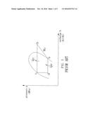
[0017] FIG. 2 is a graph showing a pressure and enthalpy relationship of a refrigeration cycle in accordance with the present invention.
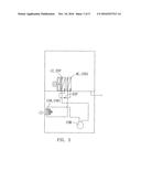
[0018] FIG. 3 is a circuit diagram of a device in accordance with a first preferred embodiment of the present invention.
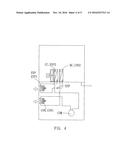
[0019] FIG. 4 is a circuit diagram of a device in accordance with a second preferred embodiment of the present invention.
[0020] FIG. 5 is a circuit diagram of a device in accordance with a third preferred embodiment of the present invention.
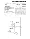
[0021] FIG. 6 is a schematic view of a humidifier of the device in accordance with the present invention.
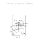
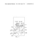
[0022] FIG. 7 is a circuit diagram of a device in accordance with a fourth preferred embodiment of the present invention.
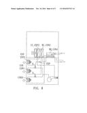
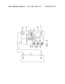
[0023] FIG. 8 is a circuit diagram of a device in accordance with a fifth preferred embodiment of the present invention.
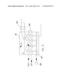
[0024] FIG. 9 is a schematic operational view of the device as shown in FIG. 8 in use.
DETAILED DESCRIPTION OF THE INVENTION
[0025] The present invention relates to a direct expansion heat recovery energy-saving method and a device which uses the method to have a cooling, dehumidifying, reheating and humidifying functions by a heat recovery.
[0026] Referring to the drawings and initially to FIG. 1, a refrigeration cycle in accordance with the prior art comprises a compression process "a-b" (by a compressor), a condensing process "b-c" (by a condenser), a throttling process "c-d" (by an expansion valve), and an evaporation process "d-a" (by an evaporator).
[0027] In the compression process "a-b",
W.sub.c=G.times.(h.sub.b-h.sub.a)
[0028] In the condensing process "b-c",
Q.sub.c=G.times.(h.sub.b-h.sub.c)
[0029] In the throttling process "c-d",
h.sub.d=h.sub.c
[0030] In the evaporation process "d-a",
Q.sub.e=G.times.(h.sub.a-h.sub.d)
[0031] The operational balance of the compressor is as follow:
Q.sub.c=Q.sub.e+W.sub.c
[0032] When Q.sub.c and Q.sub.e are not balanced, the compressor fails due to abnormal conditions of high and low pressure.
[0033] The symbols of the above-mentioned equations are described as follow:
[0034] W.sub.c=power of the compressor=KJ/S(KW)
[0035] G=mass flow rate of the refrigerant=KG/S
[0036] h=enthalpy of the refrigerant=KJ/KG
[0037] Q.sub.c=heat output per unit time of the condenser=KJ/S(KW)
[0038] Q.sub.e=heat absorption per unit time of the evaporator=KJ/S(KW)
[0039] Referring now to FIG. 2, a refrigeration cycle in accordance with the preferred embodiment of the present invention comprises a compression process "a-b" (by a compressor), a condensing process "b-c" (by a condenser), a throttling process "c-d" (by an expansion valve), and an evaporation process "d-a" (by an evaporator).
[0040] In the compression process "a-b",
W.sub.c=G.times.(h.sub.b-h.sub.a)
[0041] In the condensing process "b-c",
Q.sub.c=Q.sub.c1+Q.sub.c2
Q.sub.c1=G(h.sub.b-h.sub.X)=G.sub.f1.times.C.sub.f1.times..DELTA.T.sub.1
Q.sub.c2=Q.sub.c-Q.sub.c1=Q.sub.c-G.sub.f1.times.C.sub.f1.times..DELTA.T- .sub.1
[0042] Noted that:
[0043] Q.sub.c is a constant under a fixed condition, so that precisely controlling the value of Q.sub.c1 can precisely control the value of Q.sub.c2.
[0044] In the throttling process "c-d",
h.sub.d=h.sub.c
[0045] In the evaporation process "d-a",
Q.sub.e=Q.sub.e1+Q.sub.e2
Q.sub.e1=G(h.sub.Y-h.sub.d)=G.sub.f2.times.C.sub.f2.times..DELTA.T.sub.2
Q.sub.e2=Q-Q.sub.e1=Q.sub.e-G.sub.f2.times.C.sub.f2.times..DELTA.T.sub.2
[0046] Noted that:
[0047] Q.sub.e is a constant under a fixed condition, so that precisely controlling the value of Q.sub.e1 can precisely control the value of Q.sub.e2.
[0048] The operational balance of the compressor is as follow:
Q.sub.c=Q.sub.e+W.sub.c
(Q.sub.c1+Q.sub.c2)=(Q.sub.e1+Q.sub.e2)+W.sub.c
[0049] Q.sub.c1 and Q.sub.c2 are complementary, and Q.sub.e1 and Q.sub.e2 are complementary, so that Q.sub.c, Q.sub.e and W.sub.e are balanced easily, and the compressor will not fail due to abnormal conditions of high and low pressure.
[0050] The symbols of the above-mentioned equations are described as follow:
[0051] W.sub.c=power of the compressor=KJ/S(KW)
[0052] G=mass flow rate of the refrigerant=KG/S
[0053] h=enthalpy of the refrigerant=KJ/KG
[0054] Q.sub.c=total heat output per unit time of the condenser=KJ/S(KW)
[0055] Q.sub.c1=heat output per unit time of the first condenser=KJ/S(KW)
[0056] Q.sub.c2=heat output per unit time of the second condenser=KJ/S(KW)
[0057] G.sub.f1=mass flow rate of the secondary fluid (water or air) of the first condenser=KG/S
[0058] C.sub.f1=specific heat of the secondary fluid (water or air) of the first condenser=KJ/KG.degree. C.
[0059] .DELTA.T.sub.1=temperature differential of the secondary fluid (water or air) of the first condenser=.degree. C.
[0060] Q.sub.e=total heat absorption per unit time of the evaporator=KJ/S(KW)
[0061] Q.sub.e1=heat absorption per unit time of the first evaporator=KJ/S(KW)
[0062] Q.sub.e2=heat absorption per unit time of the second evaporator=KJ/S(KW)
[0063] G.sub.f2=mass flow rate of the secondary fluid (water or air) of the first evaporator=KG/S
[0064] C.sub.f2=specific heat of the secondary fluid (water or air) of the first evaporator=KJ/KG.degree. C.
[0065] .DELTA.T.sub.2=temperature differential of the secondary fluid (water or air) of the first evaporator=.degree. C.
[0066] In the heat output process of the present invention, at least two condensers ("CON1" and "CON2") are connected serially. Controlling the heat output Q.sub.c2 required by the second condenser is not to control the flow rate and temperature differential of the primary fluid (refrigerant) of the second condenser, but is to proportionally control the heat output Q.sub.c1 of the first condenser, that is, to form a point "X" along the line of the heat output process as shown in FIG. 2, and to let the point "X" move leftward and rightward, so as to precisely control the heat output Q.sub.c2 required by the second condenser. Thus, the total heat output in the condensing process of the refrigeration cycle is limited under a fixed condition, that is, the total heat output minus the heat output is equal to the required heat output, which is indicated by the equation of Q.sub.c-Q.sub.c1=Q.sub.c2.
[0067] In the heat input process of the present invention, at least two evaporators ("EVP1" and "EVP2") are connected serially. Controlling the heat input Q.sub.e2 required by the second evaporator is not to control the flow rate and temperature differential of the primary fluid (refrigerant) of the second evaporator, but is to proportionally control the heat input Q.sub.e1 of the first evaporator, that is, to form a point "Y" along the line of the heat input process as shown in FIG. 2, and to let the point "Y" move leftward and rightward, so as to precisely control the heat input Q.sub.e2 required by the second evaporator. Thus, the total heat input in the evaporation process of the refrigeration cycle is limited under a fixed condition, that is, the total heat input minus the heat input is equal to the required heat input, which is indicated by the equation of Q.sub.e-Q.sub.e1=Q.sub.e2.
[0068] In conclusion, the direct expansion heat recovery energy-saving method of the present invention comprises a complete refrigeration cycle including a compression process by a compressor, a condensing process by a condenser, a throttling process by an expansion valve, and an evaporation process by an evaporator. In the heat output process of the condensing process of the condenser of the present invention, at least two condensers are connected serially. The heat output required by the second condenser is to proportionally control the heat output of the first condenser, so as to precisely control the heat output required by the second condenser. The second condenser functions as a heater or humidifier of heat recovery, without affecting the normal operation of the compressor. In the heat input process of the evaporation process of the evaporator of the present invention, at least two evaporators are connected serially. The heat input required by the second evaporator is to proportionally control the heat input of the first evaporator, so as to precisely control the heat input required by the second evaporator. The second evaporator functions as a cooler and a dehumidifier, so that when the volume of the second evaporator is smaller than that of the heater of heat recovery, the system has a heating effect at a high temperature, without affecting the normal operation of the compressor.
[0069] In addition, the direct expansion heat recovery energy-saving device of the present invention is used to overcome the shortcomings of the conventional direct expansion constant temperature and humidity system. The conventional direct expansion constant temperature and humidity system only has cooling and dehumidifying functions without reheating and humidifying functions. In comparison, the direct expansion heat recovery energy-saving device of the present invention has cooling, dehumidifying, reheating and humidifying functions. In practice, the direct expansion heat recovery energy-saving device of the present invention only needs to start the compressor to provide the cooling, dehumidifying, reheating and humidifying functions by the heat recovery.
[0070] In the preferred embodiment of the present invention, the heat exchanger primarily relates to a heat exchanger of a refrigerant of a compressor refrigeration cycle. In the basic refrigeration cycle, the heat exchanger only relates to an evaporator and a condenser. In the present invention, the evaporator and the condenser have different names at different positions, but the primary function (heat exchange function) of the evaporator and the condenser is not changed. For example, the cooling coil is also an evaporator, the heating coil is also a condenser, and the humidifier is also a condenser.
[0071] In the preferred embodiment of the present invention, the heat exchanger has an air-cooled type, that is, the refrigerant performs heat exchange with the air. Alternatively, the heat exchanger may have a water-cooled type, that is, the refrigerant performs heat exchange with the water.
[0072] In the preferred embodiment of the present invention, the air-cooled fan is a fan with an axial flow. Alternatively, the air-cooled fan is a centrifugal fan.
[0073] Referring now to FIG. 3, a direct expansion heat recovery energy-saving device in accordance with the preferred embodiment of the present invention comprises a compressor "COM", a condenser "CON", an expansion valve "EXP", and an evaporator "EVP" which are connected to construct a complete refrigeration cycle. The condenser "CON" includes a first condenser "CON1" and a second condenser "CON2" which are connected serially. Controlling the heat output required by the second condenser "CON2" is to proportionally control the heat output of the first condenser "CON1", so as to precisely control the heat output required by the second condenser "CON2". The second condenser "CON2" functions as a heater of the heat recovery, without affecting the normal operation of the compressor "COM". Namely, the direct expansion heat recovery energy-saving device of the present invention only needs to start the compressor "COM" to provide the cooling, dehumidifying and heating functions by means of the heat recovery. Thus, the direct expansion heat recovery energy-saving device of the present invention is available for an industry needing the conditions of low humidity and constant temperature (lower temperature), such as a warehouse that stores foods and needs a low temperature manufacturing procedures. The second condenser "CON2" may be a heating coil "HC", and the evaporator "EVP" may be a cooling coil "CC".
[0074] Referring now to FIG. 4, the evaporator "EVP" includes a first evaporator "EVP1" and a second evaporator "EVP2" which are connected serially. Controlling the heat output required by the second condenser "CON2" is to proportionally control the heat output of the first condenser "CON1", so as to precisely control the heat output required by the second condenser "CON2". The second condenser "CON2" functions as a heater of heat recovery, without affecting the normal operation of the compressor "COM". The heat input required by the second evaporator "EVP2" is to proportionally control the heat input of the first evaporator "EVP1", so as to precisely control the heat input required by the second evaporator "EVP2". The second evaporator "EVP2" functions as a cooler and a dehumidifier, so that when the volume of the second evaporator "EVP2" is smaller than that of the heater of the heat recovery, the system has a heating effect at a high temperature, without affecting the normal operation of the compressor "COM". Namely, the direct expansion heat recovery energy-saving device of the present invention only needs to start the compressor "COM" to provide the cooling, dehumidifying and heating functions by means of the heat recovery. Thus, the direct expansion heat recovery energy-saving device of the present invention is available for an industry needing the conditions of low humidity and constant temperature (higher temperature), such as a warehouse that stores foods and needs a low temperature manufacturing procedures. The second evaporator "EVP2" may be a cooling coil "CC".
[0075] Referring now to FIG. 5, the condenser "CON" further includes a third condenser "CON3" and a fourth condenser "CON4" which are connected serially. The serially connected third condenser "CON3" and fourth condenser "CON4" are connected in parallel with the serially connected first condenser "CON1" and second condenser "CON2". The direct expansion heat recovery energy-saving device further comprises solenoid valves "S" to control and start the heating or humidifying functions of the heat recovery. Namely, the direct expansion heat recovery energy-saving device of the present invention only needs to start the compressor "COM" to provide the cooling, dehumidifying, heating and humidifying functions by means of the heat recovery. Thus, the direct expansion heat recovery energy-saving device of the present invention is available for an industry needing the conditions of constant temperature and humidity, such as a computer room, an electronic constant temperature and humidity machine, or a shell mold drying process of lost wax casting. The fourth condenser "CON4" is a humidifier "HR".
[0076] Referring now to FIG. 6, the humidifier "HR" primarily includes humidifying water, an external water source control unit "HRA", a high temperature refrigerant pipe "HRB", a compression air pipe "HRC", and an air compressor "HRD". The external water source control unit "HRA" is used to control the water level of the humidifying water. The high temperature refrigerant pipe "HRB" has a first end connected with the third condenser "CON3" and a second end connected with the expansion valve "EXP", so that the heat recovery of the high temperature refrigerant supplied by the third condenser "CON3" can heat the humidifying water to produce humidified air. The compression air pipe "HRC" is connected with the air compressor "HRD" and uses the compressed air to produce air bubbles, to increase the contact area of the air and the water, so as to enhance the humidifying quantity. It is to be noted that, the temperature of the high temperature refrigerant supplied by the third condenser "CON3" is not high enough to evaporate the water efficiently, so that it is necessary to provide an aerator, that is, the compression air pipe "HRC" and the air compressor "HRD", so as to increase the heat exchange area of the air and the water. The calculation formula is described as follows.
[0077] Calculation of the humidifying quantity of the humidifier "HR" of the heat recovery of the present invention has the following conditions. The water evaporates from a water surface in an open water tank, depending on a saturated humidity ratio corresponding to a water temperature, a humidity ratio in the air, the contact area (containing the water surface and under the water surface) of the air and the water, and the air velocity above the water surface.
[0078] The quantity of the evaporated water is expressed by:
G.sub.h=(.theta.A.sub.1+C.sub.3A.sub.2)(X.sub.s-X)
[0079] The symbols of the above-mentioned equations are described as follow:
[0080] G.sub.h=amount of the evaporated water per hour=(kg/h)
[0081] .theta.=(C1+C2 V)=evaporation coefficient=(kg/m.sup.2h)
[0082] C1=constant (no unit) under a fixed condition
[0083] C2=constant (no unit) under a fixed condition
[0084] C3=constant (kg/m.sup.2h) under a fixed condition
[0085] V=velocity of the air above the water surface=(m/s)
[0086] A1=the contact area of the air above the water surface and the water=(m.sup.2)
[0087] A2=the contact area of the tiny air bubbles under the water surface and the water=(m.sup.2)
[0088] X.sub.s=humidity ratio of saturated air water at the water temperature=(kg/kg)
[0089] X=humidity ratio in the air=(kg/kg)
[0090] It is to be noted that, the units of .theta.(kg/m.sup.2h) and V(m/s) do not match, because it is an experienced formula that is the result of experiments.
[0091] Referring now to FIG. 7, the direct expansion heat recovery energy-saving device of the present invention further comprises a second compressor "COM2" connected in parallel with the compressor "COM". In the preferred embodiment of the present invention, the device is a water-cooled double compressor heat recovery device which only needs to start the compressor to provide the cooling, dehumidifying, heating and humidifying functions by means of the heat recovery. Thus, the water-cooled double compressor heat recovery device of the present invention is available for an industry needing the conditions of constant temperature and humidity, such as a computer room, an electronic constant temperature and humidity machine, or a shell mold drying process of lost wax casting.
[0092] Referring now to FIG. 8, the condenser "CON" further includes a third condenser "CON3" and a fourth condenser "CON4" which are connected serially. The serially connected third condenser "CON3" and fourth condenser "CON4" are connected in parallel with the serially connected first condenser "CON1" and second condenser "CON2". The direct expansion heat recovery energy-saving device further comprises solenoid valves "S" to control and start the heating or humidifying functions of the heat recovery. Namely, the direct expansion heat recovery energy-saving device of the present invention only needs to start the compressor "COM" to provide the cooling, dehumidifying, heating and humidifying functions by means of the heat recovery. Thus, the direct expansion heat recovery energy-saving device of the present invention is available for an industry needing the conditions of constant temperature and humidity, such as a computer room, an electronic constant temperature and humidity machine, a sauna chamber, or a shell mold drying process of lost wax casting.
[0093] Referring now to FIG. 9, the direct expansion heat recovery energy-saving device of the present invention further comprises an air conditioner unit 1 and an exterior constant temperature and humidity space 2 connected with the air conditioner unit 1. The air conditioner unit 1 is divided into an equipment space 10 and an interior constant temperature and humidity space 11 for mounting all of the above-mentioned parts of the present invention. The interior constant temperature and humidity space 11 is provided with a supply fan "SF" connected with a supply air outlet "SA" of the exterior constant temperature and humidity space 2. The exterior constant temperature and humidity space 2 has a return air outlet "RA" connected with the interior constant temperature and humidity space 11.
[0094] Accordingly, the direct expansion heat recovery energy-saving device of the present invention directly recycles the high temperature of the refrigerant exactly into the temperature and humidity conditions required by the system, so as to completely replace the electric heater or humidifier in the present market. In addition, the direct expansion heat recovery energy-saving device of the present invention has a simplified structure and is controlled easily and stably, so that it is the optimum choice for a direct expansion constant temperature and humidity system.
[0095] It is appreciated that, the direct expansion heat recovery energy-saving device of the present invention is available for a basic circulation system with one-stage compression and one-stage expansion. Alternatively, the direct expansion heat recovery energy-saving device of the present invention is also available for a multiple compressor parallel connection system, a multi-stage compressor system, a refrigerant circuit parallel connection system, a multi-stage expansion system, or a multiple refrigerant system.
[0096] Although the invention has been explained in relation to its preferred embodiment(s) as mentioned above, it is to be understood that many other possible modifications and variations can be made without departing from the scope of the present invention. It is, therefore, contemplated that the appended claim or claims will cover such modifications and variations that fall within the true scope of the invention.
User Contributions:
Comment about this patent or add new information about this topic:
Images included with this patent application:
 |  |
 |  |
 |  |
 |  |
 |  |
 |
| New patent applications in this class: | |
| Date | Title |
|---|---|
| 2022-09-22 | Electronic device |
| 2022-09-22 | Front-facing proximity detection using capacitive sensor |
| 2022-09-22 | Touch-control panel and touch-control display apparatus |
| 2022-09-22 | Sensing circuit with signal compensation |
| 2022-09-22 | Reduced-size interfaces for managing alerts |