Patent application title: METHOD AND ELECTRONIC APPARATUS FOR TRANSMITTING PACKET WITH CHANGEABLE SPREADING FACTOR
Inventors:
Jianhan Liu (San Jose, CA, US)
Jianhan Liu (San Jose, CA, US)
Chien-Fang Hsu (Taoyuan City, TW)
IPC8 Class: AH04B17097FI
USPC Class:
1 1
Class name:
Publication date: 2016-10-13
Patent application number: 20160301445
Abstract:
The present invention provides a method and an electronic apparatus for
transmitting a packet with changeable spreading factor. The method
comprises: utilizing a spreading circuit to select a spreading factor
from a plurality of spreading factors according to a transmitting
condition to adjust a spreading for the packet; and transmitting the
packet. The electronic apparatus comprises: a spreading circuit and a
transmitting circuit. The spreading circuit is utilized for selecting a
spreading factor from a plurality of spreading factors according to a
transmitting condition to adjust the spreading for the packet. The
transmitting circuit is coupled to the spreading circuit, and utilized
for transmitting the packet.Claims:
1. A method for transmitting a packet, comprising: utilizing a spreading
circuit to select a spreading factor from a plurality of spreading
factors according to a transmitting condition to adjust a spreading for
the packet; and transmitting the packet.
2. The method of claim 1, wherein the spreading uses Barker Sequences.
3. The method of claim 1, wherein a packet type of the packet is control PHY in IEEE 802.11aj specification.
4. The method of claim 1, wherein the spreading factor signaling information is conveyed by a field of the control PHY header.
5. The method of claim 1, wherein the spreading factor field of the control PHY header has two bits.
6. The method of claim 1, wherein the spreading factors are Barker sequence 4, Barker sequence 7, Barker sequence 13, and no spreading.
7. An electronic apparatus for transmitting a packet, comprising: a spreading circuit, for selecting a spreading factor from a plurality of spreading factors according to a transmitting condition to adjust a spreading for the packet; and a transmitting circuit, coupled to the spreading circuit, for transmitting the packet.
8. The electronic apparatus of claim 7, wherein the spreading uses Barker Sequences.
9. The electronic apparatus of claim 7, wherein a packet type of the packet is control PHY in IEEE 802.11aj specification.
10. The electronic apparatus of claim 7, wherein the spreading factor signaling information is conveyed by a field of the control PHY header.
11. The electronic apparatus of claim 7, wherein the spreading factor filed of the control PHY header has two bits.
12. The electronic apparatus of claim 7, wherein the spreading factors are Barker sequence 4, Barker sequence 7, Barker sequence 13, and no spreading.
13. The electronic apparatus of claim 7, applied to 40-50 GHz Millimeter Wave Communication Systems.
Description:
CROSS REFERENCE TO RELATED APPLICATIONS
[0001] This application claims the benefit of U.S. Provisional Application No. 62/143,909, filed on Apr. 7, 2015 and included herein by reference.
BACKGROUND
[0002] In IEEE 802.11aj specifications, Control PHY is only transmitted in 540 MHz channel. In a conventional Control PHY design and a conventional transmitting method, there is a fixed spreading factor. For example, using a fixed spreading factor, 16, always provides signal-to-noise ratio (SNR) enhancement of 12 dB. Thus, the conventional transmitting method with a fixed spreading factor causes unnecessary high power consumption when a transmitting condition is not bad. In addition, to support up to 10 m Non-line-of-sight (NLOS) transmission, station discovery and beamforming training need Control PHY to work in low SNR environments. Thus, an innovative Control PHY design and transmitting method are required.
SUMMARY
[0003] It is therefore one of the objectives of the disclosure to provide a method and an electronic apparatus for provide a Control PHY with low implementation complexity and good performance with lower power consumption, and the spreading factor is changeable for flexible designs and different spectrum efficiency, so as to solve the problem mentioned above.
[0004] In accordance with an embodiment of the present invention, a method for transmitting a packet is disclosed. The method comprises: utilizing a spreading circuit to select a spreading factor from a plurality of spreading factors according to a transmitting condition to adjust a spreading for the packet; and transmitting the packet.
[0005] In accordance with an embodiment of the present invention, an electronic apparatus for transmitting a packet is disclosed. The electronic apparatus comprises: a spreading circuit and a transmitting circuit. The spreading circuit is utilized for selecting a spreading factor from a plurality of spreading factors according to a transmitting condition to adjust the spreading for the packet. The transmitting circuit is coupled to the spreading circuit, and utilized for transmitting the packet.
[0006] Briefly summarized, the method and the electronic apparatus disclosed by the embodiments can provide a Control PHY with low implementation complexity and good performance with lower power consumption, wherein the spreading factor is changeable for flexible designs and different spectrum efficiency.
[0007] These and other objectives of the present invention will no doubt become obvious to those of ordinary skill in the art after reading the following detailed description of the preferred embodiment that is illustrated in the various figures and drawings.
BRIEF DESCRIPTION OF THE DRAWINGS
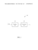
[0008] FIG. 1 is a simplified diagram of an electronic apparatus for transmitting a packet in accordance with an embodiment of the present invention.
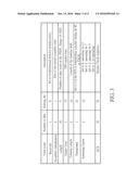
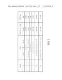
[0009] FIG. 2 illustrates a Barker sequence table in accordance with an embodiment of the present invention.
[0010] FIG. 3 illustrates a field control PHY header in accordance with an embodiment of the present invention.
[0011] FIG. 4 is an exemplary flowchart showing a method in accordance with operation schemes of electronic apparatus in FIG. 1.
DETAILED DESCRIPTION
[0012] Certain terms are used throughout the description and following claims to refer to particular components. As one skilled in the art will appreciate, manufacturers may refer to a component by different names. This document does not intend to distinguish between components that differ in name but not function. In the following description and in the claims, the terms "include" and "comprise" are used in an open-ended fashion, and thus should be interpreted to mean "include, but not limited to". Also, the term "couple" is intended to mean either an indirect or direct electrical connection. Accordingly, if one device is coupled to another device, that connection may be through a direct electrical connection, or through an indirect electrical connection via other devices and connections.
[0013] Please refer to FIG. 1. FIG. 1 is a simplified diagram of an electronic apparatus 100 for transmitting a packet in accordance with an embodiment of the present invention, wherein the electronic apparatus 100 can be a transmitter (TX) of a smartphone or a tablet, and can be applied to 40-50 GHz millimeter wave communication systems, and a packet type of the packet can be control PHY in IEEE 802.11aj specification. However, other electronic device operating at different frequencies or following different standards may also apply. The electronic apparatus 100 comprises: a spreading circuit 110 and a transmitting circuit 120. The spreading circuit 110 is utilized for selecting a spreading factor from a plurality of spreading factors according to a transmitting condition to adjust the spreading for the packet, wherein in the design of the present invention, the spreading can use Barker Sequence which is a finite sequence of N values of +1 and -1 with ideal correlation property since Barker Sequence has the lowest sidelobe level ratio among all binary sequences. In addition, the spreading factor signaling information can be conveyed by a field in the control PHY header, and the spreading factor can be represented with two bits, for example. The transmitting circuit 120 is coupled to the spreading circuit 110, and utilized for transmitting the packet.
[0014] For example, please refer to FIG. 2. FIG. 2 illustrates a Barker sequence table in accordance with an embodiment of the present invention. As shown in FIG. 2, the design of the present invention chooses Barker sequence 4, Barker sequence 7, Barker sequence 13 as spreading factors 4, 7, and 13, respectively, wherein the spreading factor 4 provides 6 dB SNR enhancement, and the spreading factor 7 provides 8.4 dB SNR enhancement, and the spreading factor 13 provides 11.1 dB SNR enhancement. In addition, please refer to FIG. 3. FIG. 3 illustrates a field of the control PHY header in accordance with an embodiment of the present invention. As shown in FIG. 3, the spreading factor signaling information is conveyed by the spreading factor field in the control PHY header, wherein the starting bit of the spreading factor is 22, and the number of bits of the spreading factor is 2. Thus, the spreading circuit 110 can select a spreading factor from four spreading factors according to a transmitting condition to adjust the spreading for the packet. For example, if the transmitting condition is good enough without spreading, then the spreading circuit 110 will select the spreading factor of no spreading. If the transmitting condition requires a low SNR gain (such as not higher than 6 dB), then the spreading circuit 110 will select the spreading factor 4 to adjust the spreading for the packet. If the transmitting condition requires a medium SNR gain (such as higher than 6 dB but not higher than 8.4 dB), then the spreading circuit 110 will select the spreading factor 7 to adjust the spreading for the packet. If the transmitting condition requires a high SNR gain (such as higher than 8.4 dB but not higher than 11.1 dB), then the spreading circuit 110 will select the spreading factor 13 to adjust the spreading for the packet.
[0015] According to another embodiment of the present invention, the spreading circuit 110 may start with a code with the longest length, such as the code with a length of 13 shown in FIG. 2. The spreading circuit 110 may then use a code with a different length according to the channel condition or the transmitting condition. For example, if the channel condition gets better, a code with a shorter length is used. If the channel condition gets worse or remains the same, the spreading circuit 110 may use a code with the same length or a code with a longer length. However, the adjustment of the length of the code does not have to use the very next code. If the channel condition gets much better, a much shorter code can be used. For example, a code with a length 13 is first used, then a code with a length of 5 or 7 can be used if the channel condition gets much better. Similarly, when a code with a length of 4 is currently used, a code with a length 11 can then be used if the channel condition degrades dramatically. Please note that the above embodiments are only for an illustrative purpose and are not meant to be a limitation of the present invention. For example, the field control PHY header design and the Barker sequence table can be changed according to different design requirements.
[0016] In this way, the spreading factor is changeable for flexible designs and different spectrum efficiency in the present invention, and the present invention can provide a Control PHY with low implementation complexity and good performance with lower power consumption.
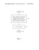
[0017] Please refer to FIG. 4. FIG. 4 is an exemplary flowchart showing a method in accordance with operation schemes of electronic apparatus 100 in the above embodiment. Provided that the result is substantially the same, the steps in FIG. 4 are not required to be executed in the exact order shown in FIG. 4. The method in accordance with the above embodiment of the electronic apparatus 100 in the present invention comprises the following steps:
[0018] Step 200: Start.
[0019] Step 210: Utilize a spreading circuit to select a spreading factor from a plurality of spreading factors according to a transmitting condition to adjust a spreading for the packet.
[0020] Step 220: Transmit the packet.
[0021] Step 230: End
[0022] Briefly summarized, the method and the electronic apparatus disclosed by the embodiments can provide a Control PHY with low implementation complexity and good performance with lower power consumption, wherein the spreading factor is changeable for flexible designs and different spectrum efficiency.
[0023] Those skilled in the art will readily observe that numerous modifications and alterations of the device and method may be made while retaining the teachings of the invention. Accordingly, the above disclosure should be construed as limited only by the metes and bounds of the appended claims.
User Contributions:
Comment about this patent or add new information about this topic:
| People who visited this patent also read: | |
| Patent application number | Title |
|---|---|
| 20200243097 | Audio Recording Optimization for Calls Serviced by an Artificial Intelligence Agent |
| 20200243096 | DOWNMIXER AND METHOD FOR DOWNMIXING AT LEAST TWO CHANNELS AND MULTICHANNEL ENCODER AND MULTICHANNEL DECODER |
| 20200243095 | Device, System, and Method for Assigning Differential Weight to Meeting Participants and for Generating Meeting Summaries |
| 20200243094 | SWITCHING BETWEEN SPEECH RECOGNITION SYSTEMS |
| 20200243093 | SERVER AND METHOD FOR CONTROLLING EXTERNAL DEVICE |
Images included with this patent application:
 |  |
 |  |
 |
| Similar patent applications: | |
| Date | Title |
|---|---|
| 2017-04-20 | Throttle emulator |
| 2017-04-20 | Method and apparatus for purification and treatment of air |
| New patent applications in this class: | |
| Date | Title |
|---|---|
| 2022-09-22 | Electronic device |
| 2022-09-22 | Front-facing proximity detection using capacitive sensor |
| 2022-09-22 | Touch-control panel and touch-control display apparatus |
| 2022-09-22 | Sensing circuit with signal compensation |
| 2022-09-22 | Reduced-size interfaces for managing alerts |
| New patent applications from these inventors: | |
| Date | Title |
|---|---|
| 2022-08-25 | Eht-ltf sequence design for distributed-tone resource units with papr reduction |
| 2022-08-18 | Eht-stf transmission for distributed-tone resource units in 6ghz low-power indoor systems |
| 2022-08-18 | Pilot tone design for distributed-tone resource units in 6ghz low-power indoor systems |
| 2022-08-11 | Signaling for ul tb ppdu with distributed-tone resource units in 6ghz low-power indoor systems |
| 2022-08-04 | Tone alignment for distributed-tone resource units in 6ghz low-power indoor systems |