Patent application title: METHOD FOR OPTIMIZING FLIGHT SPEED OF REMOTELY-SENSED SCAN IMAGING PLATFORM
Inventors:
Xiaobo Zou (Jiangsu, CN)
Jiyong Shi (Jiangsu, CN)
Jiewen Zhao (Jiangsu, CN)
Xiaowei Huang (Jiangsu, CN)
Yaodi Zhu (Jiangsu, CN)
Zhihua Li (Jiangsu, CN)
Assignees:
JIANGSU UNIVERSITY
IPC8 Class: AG05D1302FI
USPC Class:
1 1
Class name:
Publication date: 2016-10-13
Patent application number: 20160299513
Abstract:
A method for optimizing a flight speed of a remotely-sensed scan imaging
platform. The method comprises: selecting a reference point; obtaining a
remotely-sensed scan image in a reference point region, and processing
data; and optimizing a flight speed of a remotely-sensed scan platform.
By optimizing a movement speed of a remotely-sensed movement platform,
the method can prevent a geometric dimension of a target in a
remotely-sensed scan image from being distorted, so as to obtain a
high-precision remotely-sensed image of a ground target; and the method
can be used for airborne and satellite borne remotely-sensed images.Claims:
1. A method for optimizing flight speed of a remotely-sensed scan imaging
platform, characterized in that it includes the following steps: Step 1:
Selecting reference points: selecting point A and point B on the ground
as reference points, wherein the distance between point A and point B is
L.sub.AB km; selecting the central point of the connecting line of point
A and point B as a reference point C; selecting point D as another
reference point to make the connecting line CD of point D and point C
perpendicular to the connecting line AB of point A and point B, and the
distance between point D and point C be L.sub.CD km; Step 2: Obtaining a
remotely-sensed scan image in a reference point region, and processing
data; Step 3: Optimizing the flight speed of the remotely-sensed scan
imaging platform.
2. The method for optimizing flight speed of a remotely-sensed scan imaging platform according to claim 1, characterized in that "Step 2: Obtaining a remotely-sensed scan image in a reference point region, and processing data" further includes: using a remotely-sensed scan platform to carry a remote sensing camera to obtain the remotely-sensed images A', B', C' and D' of reference points A, B, C and D at a movement speed V; and calculating the distance between A' and B' in the remotely-sensed images as L.sub.A'B' pixels, and the distance between C' and D' as L.sub.C'D' pixels.
3. The method for optimizing flight speed of a remotely-sensed scan imaging platform according to claim 1, characterized in that "Step 3: Optimizing the flight speed of the remotely-sensed scan imaging platform" further includes: calculating the optimized movement speed V' of the remotely-sensed scan platform by using the movement speed V of the remotely-sensed scan platform, distance L.sub.A'B' between A' and B' in the remotely-sensed images, distance L.sub.C'D' between C' and D', distance L.sub.AB between point A and point B and distance L.sub.CD between point D and point C according to the formula of V ' = V L AB L C ' D ' L CD L A ' B ' . ##EQU00003##
Description:
FIELD OF THE INVENTION
[0001] The present invention relates to the field of remote sensing detection technology, particularly to a method for optimizing flight speed of a remotely-sensed scan imaging platform.
BACKGROUND OF THE INVENTION
[0002] Remote sensing detection technology is a comprehensive technology, which applies various sensors to collect and process the information of electromagnetic wave radiated and reflected by remote targets according to the theory of electromagnetic waves, for finally imaging and thereby detecting and identifying the sceneries on the ground. By applying remote sensing technology, maps can be plotted at a high speed with high quality. The ways of remotely-sensed imaging include photographic imaging and scan imaging. The way of scan imaging requires the remotely-sensed scan platform to carry a remote sensing camera and fly over the imaging region at a constant relative speed. In order to prevent distortion of geometric dimensions of a target in a remotely-sensed scan image, the flight speed of the remotely-sensed imaging platform should be calibrated. The literature "integrated calibration method of agricultural product scanning and hyperspectral imaging system" (Transactions of the Chinese Society of Agricultural Engineering, Issue No. 14, Volume 28 of 2012, pages 244-249) discloses a method for calibrating scanning speed and correcting guide rail deviation, thus ensuring the accuracy of imaging data. This method adopts a specific corrector plate to correct the image collection system, whereas, during remotely-sensed scan imaging, the scanning speed cannot be calculated by a similar method.
[0003] For this reason, the present invention provides a method for optimizing flight speed of a remotely-sensed scan imaging platform to solve the foregoing problem.
SUMMARY OF THE INVENTION
[0004] The object of the present invention is to provide a method for optimizing flight speed of a remotely-sensed scan imaging platform, so as to realize high-precision remotely-sensed scan imaging of ground targets.
[0005] In order to solve the foregoing technical problem, the present invention adopts the following technical scheme:
[0006] A method for optimizing flight speed of a remotely-sensed scan imaging platform, characterized in that it includes the following steps:
[0007] Step 1: Selecting reference points: selecting point A and point B on the ground as reference points, wherein the distance between point A and point B is L.sub.AB km; selecting the central point of the connecting line of point A and point B as a reference point C; selecting point D as another reference point to make the connecting line CD of point D and point C perpendicular to the connecting line AB of point A and point B, and the distance between point D and point C be L.sub.CD km;
[0008] Step 2: Obtaining a remotely-sensed scan image in a reference point region, and processing data;
[0009] Step 3: Optimizing the flight speed of the remotely-sensed scan imaging platform.
"Step 2: Obtaining a remotely-sensed scan image in a reference point region, and processing data" further includes: using a remotely-sensed scan platform to carry a remote sensing camera to obtain the remotely-sensed images A', B', C' and D' of reference points A, B, C and D at a movement speed V; calculating the distance between A' and B' in the remotely-sensed images as L.sub.A'B' pixels, and the distance between C' and D' as L.sub.C'D' pixels. "Step 3: Optimizing flight speed of the remotely-sensed scan imaging platform" further includes: calculating the optimized movement speed V' of the remotely-sensed scan platform by using the movement speed V of the remotely-sensed scan platform, distance L.sub.A'B' between A' and B' in the remotely-sensed images, distance L.sub.C'D' between C' and D', distance L.sub.AB between point A and point B and distance L.sub.CD between point D and point C. The calculation formula is
V ' = V L AB L C ' D ' L CD L A ' B ' . ##EQU00001##
[0010] The present invention has the following beneficial effects: through optimizing the movement speed of the remotely-sensed mobile platform, the present invention can prevent the geometric dimensions of a target in a remotely-sensed scan image from being distorted so as to obtain a high-precision remotely-sensed image of ground target.
BRIEF DESCRIPTION OF THE DRAWINGS
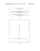
[0011] FIG. 1 is a flow diagram of the present invention;
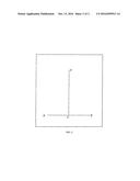
[0012] FIG. 2 is a schematic diagram of reference points A, B, C and D;
[0013] FIG. 3 is a schematic diagram of points A', B', C' and D' corresponding to reference points A, B, C and D in the remotely-sensed images;
DETAILED DESCRIPTION OF THE EMBODIMENTS
[0014] Below the present invention will be described in details with reference to the accompanying drawings and specific embodiments, but these embodiments are not intended to limit the present invention. The structural, methodological or functional modifications made by those skilled in the art according to these embodiments fall within the scope of protection of the present invention.
[0015] As shown in FIG. 1, the method for optimizing flight speed of a remotely-sensed scan imaging platform includes the following steps:
[0016] Step 1: Selecting reference points;
[0017] Step 2: Obtaining a remotely-sensed scan image in a reference point region, and processing data;
[0018] Step 3: Optimizing the flight speed of the remotely-sensed scan imaging platform;
[0019] As shown in FIG. 2, "Step 1: Selecting reference points" is characterized by: selecting point A and point B on the ground as reference points, wherein the distance between point A and point B is L.sub.AB=100 km; selecting the central point of the connecting line of point A and point B as a reference point C; selecting point D as another reference point to make the connecting line CD of point D and point C perpendicular to the connecting line AB of point A and point B, and the distance between point D and point C be L.sub.CD=10000 km
[0020] As shown in FIG. 3, "Step 2: Obtaining a remotely-sensed scan image in a reference point region, and processing data" is characterized by: using a remotely-sensed scan platform to carry a remote sensing camera to obtain the remotely-sensed images A', B', C' and D' of reference points A, B, C and D at a movement speed V=120 KM/H; and calculating the distance between A' and B' in the remotely-sensed images as L.sub.A'B'=1200 pixels, and the distance between C' and D' as L.sub.C'D'=114000 pixels.
[0021] "Step 3: Optimizing the flight speed of the remotely-sensed scan imaging platform" is characterized by: calculating the optimized movement speed V' of the remotely-sensed scan platform by using the movement speed V=120 KM/H, L.sub.A'B'=1,200 pixels, L.sub.C'D'=114,000 pixels, L.sub.AB=100 KM, L.sub.CD=10,000 KM according to the formula of
V ' = V L AB L C ' D ' L CD L A ' B ' = 114 KM / H . ##EQU00002##
User Contributions:
Comment about this patent or add new information about this topic:
Images included with this patent application:
 |  |
 |
| Similar patent applications: | |
| Date | Title |
|---|---|
| 2016-08-18 | Transparent template and positioning device with overlapping lines forming a halo effect |
| 2016-08-18 | Boresight insert for alignment of aiming system with firing system of weapon |
| 2016-08-11 | Rotating slit-scan fundus imager |
| 2016-08-18 | Light source utilizing wavelength conversion |
| 2016-08-04 | Method and apparatus for sorting or retreiving items |
| New patent applications in this class: | |
| Date | Title |
|---|---|
| 2022-09-22 | Electronic device |
| 2022-09-22 | Front-facing proximity detection using capacitive sensor |
| 2022-09-22 | Touch-control panel and touch-control display apparatus |
| 2022-09-22 | Sensing circuit with signal compensation |
| 2022-09-22 | Reduced-size interfaces for managing alerts |
| New patent applications from these inventors: | |
| Date | Title |
|---|---|
| 2014-09-04 | Multi-sensor based automatic brewing mass overturn machine |
| 2013-08-08 | Hyperspectral imaging light source system |