Patent application title: FREQUENCY SHIFTING A COMMUNICATIONS SIGNAL(S) IN A MULTI-FREQUENCY DISTRIBUTED ANTENNA SYSTEM (DAS) TO AVOID OR REDUCE FREQUENCY INTERFERENCE
Inventors:
Dror Harel (Hod Hasharon, IL)
Dror Harel (Hod Hasharon, IL)
IPC8 Class: AH04L2503FI
USPC Class:
375334
Class name: Receivers angle modulation frequency shift keying
Publication date: 2016-05-12
Patent application number: 20160134439
Abstract:
Frequency shifting a communications signal(s) in a multiple frequency
(multi-frequency) distributed antenna system (DAS) to avoid or reduce
frequency interference is disclosed. Related devices, methods, and DASs
are disclosed. Non-limiting examples of frequency interference include
frequency band interference and frequency channel interference. As a
non-limiting example, frequency interference in a multi-frequency DAS may
result from non-linearity of a signal processing component generating an
out-of-band harmonic of a first, in-use communications signal in a first
frequency band, within different frequency band(s) of other in-use
communications signal(s). To avoid or reduce such interference,
embodiments disclosed herein involve predicting frequency interference
that may result from processing received, in-use communications signals
in multiple frequency bands to be distributed in a multi-frequency DAS.
Frequency shifting is performed to avoid or reduce any interfering signal
products produced from the signal processing of any in-use communications
signals, from interfering in the frequencies of other in-use
communications signals.Claims:
1. A frequency interference prediction system, comprising: a
communications signal interface configured to provide communications to a
plurality of antennas in a wireless communication system, comprising: a
first communications signal interface configured to receive at least one
first communications signal in at least one first frequency range; and a
second communications signal interface configured to receive at least one
second communications signal in at least one second frequency range
different from the at least one first frequency range; a first
communications signal path communicatively coupled to the first
communications signal interface, the first communications signal path
comprising: a first frequency shifting circuit configured to frequency
shift the at least one first communications signal from a first frequency
in the at least one first frequency range to a shifted first
communications signal at a shifted first frequency based on a first
frequency control signal; a second communications signal path
communicatively coupled to the second communications signal interface and
configured to provide the at least one second communications signal as an
output second communications signal to a second communications signal
path output; a combiner communicatively coupled to a first communications
signal path output and the second communications signal path output, the
combiner configured to combine an output first communications signal and
the output second communications signal into a combined multi-frequency
communications signal; an electrical-to-optical converter configured to
convert the combined multi-frequency communications signal into an
optical combined multi-frequency communications signal; and a controller
configured to: predict frequency interference in the combined
multi-frequency communications signal; and if frequency interference is
predicted in the combined multi-frequency communications signal:
determine the shifted first frequency to shift the at least one first
communications signal in the combined multi-frequency communications
signal; and set the first frequency control signal to cause the first
frequency shifting circuit to frequency shift the at least one first
communications signal to the shifted first communications signal at the
shifted first frequency.
2. The frequency interference prediction system of claim 1, wherein the controller is configured to: predict the frequency interference in the combined multi-frequency communications signal based on a first interfering signal product generated from signal processing of the at least one first communications signal in the multi-frequency DAS, interfering in the at least one second frequency range of the at least one second communications signal; and if frequency interference from the first interfering signal product is predicted in the combined multi-frequency communications signal, determine the shifted first frequency to shift the at least one first communications signal in the combined multi-frequency communications signal so that the first interfering signal product does not interfere with the at least one second frequency range of the at least one second communications signal.
3. The frequency interference prediction system of claim 2, wherein the second communications signal path comprises a second frequency shifting circuit configured to frequency shift the at least one second communications signal from a second frequency to a shifted second communications signal at a shifted second frequency based on a second frequency control signal.
4. The frequency interference prediction system of claim 2, further comprising a first selector circuit configured to selectively provide the at least one first communications signal or the shifted first communications signal as the output first communications signal to the first communications signal path output, in response to a first selector control signal, wherein the controller further configured to, if frequency interference is predicted in the combined multi-frequency communications signal, generate the first selector control signal to cause the first selector circuit to provide the shifted first communications signal as the output first communications signal to the first communications signal path output.
5. The frequency interference prediction system of claim 2, wherein: the at least one first communications signal is in a first frequency band; the at least one second communications signal is in a second frequency band; the first frequency shifting circuit is configured to frequency shift the at least one first communications signal from the first frequency band to the shifted first communications signal at a shifted first frequency band based on the first frequency control signal; and the controller is configured to: predict frequency band interference in the combined multi-frequency communications signal, based on the first interfering signal product generated from signal processing of the at least one first communications signal in the multi-frequency DAS interfering in the second frequency band of the at least one second communications signal; if the frequency band interference from the first interfering signal product is predicted in the combined multi-frequency communications signal, set the first frequency control signal to cause the first frequency shifting circuit to frequency shift the at least one first communications signal to the shifted first communications signal at the shifted first frequency outside of the second frequency band of the at least one second communications signal.
6. The frequency interference prediction system of claim 2, wherein: the at least one first communications signal is in at least one first frequency channel; the at least one second communications signal is in at least one second frequency channel; the first frequency shifting circuit is configured to frequency shift the at least one first communications signal from the at least one first frequency channel to the shifted first communications signal at a shifted first frequency channel based on the first frequency control signal; and the controller is configured to: predict frequency channel interference in the combined multi-frequency communications signal based on the first interfering signal product generated from signal processing of the at least one first communications signal in the multi-frequency DAS, interfering in the at least one second frequency channel of the at least one second communications signal; if the frequency channel interference from the first interfering signal product is predicted in the combined multi-frequency communications signal, set the first frequency control signal to cause the first frequency shifting circuit to frequency shift the at least one first communications signal to the shifted first communications signal at the shifted first frequency channel outside of the at least one second frequency channel of the at least one second communications signal.
7. The frequency interference prediction system of claim 1, wherein the controller is configured to: predict the frequency interference in the combined multi-frequency communications signal, based on a second interfering signal product generated from signal processing of the at least one second communications signal in the multi-frequency DAS interfering in the at least one first frequency range of the at least one first communications signal; and if frequency interference from the second interfering signal product is predicted in the combined multi-frequency communications signal, determine the shifted first frequency to shift the at least one first communications signal in the combined multi-frequency communications signal so that the second interfering signal product does not interfere with the at least one first frequency range of the at least one first communications signal.
8. The frequency interference prediction system of claim 1, wherein the controller is further configured to provide a synchronization control signal based on the first frequency control signal in the combined multi-frequency communications signal.
9. The frequency interference prediction system of claim 1, wherein the first frequency shifting circuit comprises: a first synthesizer configured to receive the first frequency control signal and generate a first mixing frequency signal based on the received first frequency control signal; and a first mixer configured to receive the first mixing frequency signal and the at least one first communications signal, and mix the first mixing frequency signal with the at least one first communications signal to generate the shifted first communications signal.
10. A method of avoiding or reducing frequency interference, comprising: receiving at least one first communications signal in at least one first frequency range comprising a first communications signal path output; receiving at least one second communications signal in at least one second frequency range different from the at least one first frequency range comprising a second communications signal path output; predicting frequency interference in a combined multi-frequency communications signal comprising the at least one first communications signal combined with the at least one second communications signal, as a result of an interfering signal product produced as a result of signal processing at least one of the at least one first communications signal and the at least one second communications signal; if frequency interference is predicted in the combined multi-frequency communications signal: determining a shifted first frequency to shift the at least one first communications signal in the combined multi-frequency communications signal; frequency shifting the at least one first communications signal to a shifted first communications signal at the shifted first frequency; and providing the shifted first communications signal as an output first communications signal to the first communications signal path output; and combining the first communications signal path output and the second communications signal path output to provide the combined multi-frequency communications signal.
11. The method of claim 10, wherein: predicting the frequency interference in the combined multi-frequency communications signal comprises predicting the frequency interference in the combined multi-frequency communications signal based on a first interfering signal product generated from signal processing of the at least one first communications signal in the multi-frequency DAS, interfering in the at least one second frequency range of the at least one second communications signal; and if frequency interference from the first interfering signal product is predicted in the combined multi-frequency communications signal, determining the shifted first frequency by determining the shifted first frequency to shift the at least one first communications signal in the combined multi-frequency communications signal so that the first interfering signal product does not interfere with the at least one second frequency range of the at least one second communications signal.
12. The method of claim 10, wherein: predicting the frequency interference in the combined multi-frequency communications signal comprises predicting the frequency interference in the combined multi-frequency communications signal based on a second interfering signal product generated from signal processing of the at least one second communications signal in the multi-frequency DAS interfering in the at least one first frequency range of the at least one first communications signal; and if frequency interference from the second interfering signal product is predicted in the combined multi-frequency communications signal, determining the shifted first frequency by determining the shifted first frequency to shift the at least one first communications signal in the combined multi-frequency communications signal so that the second interfering signal product does not interfere with the at least one first frequency range of the at least one first communications signal.
13. A multiple frequency communication system, comprising: a central unit configured to: receive a combined uplink multi-frequency communications signal from a plurality of remote units; receive a first downlink communications signal in at least one first frequency range and a second downlink communications signal in at least one second frequency range different from the at least one first frequency range; and distribute the first downlink communications signal as an output first downlink communications signal to a first downlink communications signal path output and the second downlink communications signal as an output second downlink communications signal to a second downlink communications signal path output; the central unit comprising: a combiner communicatively coupled to the first downlink communications signal path output and the second downlink communications signal path output, the combiner configured to combine the output first downlink communications signal and the output second downlink communications signal into a combined downlink multi-frequency communications signal; and an electrical-to-optical converter configured to convert the combined multi-frequency communications signal into an optical signal; the plurality of remote units each configured to: receive the combined downlink multi-frequency communications signal from the central unit and distribute the combined downlink multi-frequency communications signal from the central unit to at least one client device; receive a first uplink communications signal in at least one first frequency range and a second uplink communications signal in at least one second frequency range different from the at least one first frequency range; and distribute the first uplink communications signal as an output first uplink communications signal to a first uplink communications signal path output and the second uplink communications signal as an output second uplink communications signal to a second uplink communications signal path output; at least one of the remote units comprising: a combiner communicatively coupled to the first uplink communications signal path output and the second uplink communications signal path output, the combiner configured to combine the output first uplink communications signal and the output second uplink communications signal into a combined uplink multi-frequency communications signal; a frequency interference prediction system, comprising: a first communications signal path, comprising: a first frequency shifting circuit configured to frequency shift at least one first communications signal among the first downlink communications signal and the first uplink communications signal from a first frequency to a shifted first communications signal at a shifted first frequency based on a first frequency control signal; a second communications signal path configured to provide at least one second communications signal among the second downlink communications signal and the second uplink communications signal as an output second communications signal to a second communications signal path output among the second downlink communications signal path output and the second uplink communications signal path output; and a controller configured to: predict frequency interference in a combined multi-frequency communications signal among the combined downlink multi-frequency communications signal and the combined uplink multi-frequency communications signal; if frequency interference is predicted in the combined multi-frequency communications signal: determine the shifted first frequency to shift the at least one first communications signal in the combined multi-frequency communications signal; and set the first frequency control signal to cause the first frequency shifting circuit to frequency shift the at least one first communications signal to the shifted first communications signal at the shifted first frequency.
14. The multi-frequency system of claim 13, wherein the frequency interference prediction system comprises: a communications signal interface, comprising: a first communications signal interface configured to receive the at least one first communications signal in the at least one first frequency range; and a second communications signal interface configured to receive the at least one second communications signal in the at least one second frequency range different from the at least one first frequency range.
15. The multi-frequency system of claim 13, wherein the controller is configured to: predict the frequency interference in the combined multi-frequency communications signal based on a first interfering signal product generated from signal processing of the at least one first communications signal in the multi-frequency DAS, interfering in the at least one second frequency range of the at least one second communications signal; and if frequency interference from the first interfering signal product is predicted in the combined multi-frequency communications signal, determine the shifted first frequency to shift the at least one first communications signal in the combined multi-frequency communications signal so that the first interfering signal product does not interfere with the at least one second frequency range of the at least one second communications signal.
16. The multi-frequency system of claim 13, wherein the first frequency shifting circuit comprises: a first synthesizer configured to receive the first frequency control signal and generate a first mixing frequency signal based on the received first frequency control signal; and a first mixer configured to receive the first mixing frequency signal and the at least one first communications signal, and mix the first mixing frequency signal with the at least one first communications signal to generate the shifted first communications signal.
Description:
CROSS-REFERENCE TO RELATED APPLICATION
[0001] This is a continuation application of U.S. patent application Ser. No. 14/824,660, filed on Aug. 12, 2015, which is a continuation of U.S. patent application Ser. No. 14/496,349, filed on Sep. 25, 2014, now U.S. Pat. No. 9,184,960, the contents of which are relied upon and incorporated herein by reference in their entireties, and the benefit of priority under 35 U.S.C. §120 is hereby claimed.
BACKGROUND
[0002] The technology of the present disclosure relates generally to distributed antenna systems (DASs), and more particularly to frequency shifting a communications signal(s) in a multiple frequency (multi-frequency) DAS to avoid or reduce potential frequency band interference, such as due to out-of-band harmonics generated by non-linearities in signal processing components.
[0003] Wireless communication is rapidly growing, with ever-increasing demands for high-speed mobile data communication. As an example, local area wireless services (e.g., so-called "wireless fidelity" or "WiFi" systems) and wide area wireless services are being deployed in many different types of areas (e.g., coffee shops, airports, libraries, etc.). Distributed communications or antenna systems communicate with wireless devices called "clients," "client devices," or "wireless client devices," which must reside within the wireless range or "cell coverage area" in order to communicate with an access point device. Distributed antenna systems are particularly useful to be deployed inside buildings or other indoor environments where client devices may not otherwise be able to effectively receive radio-frequency (RF) signals from a source, such as a base station for example. Example applications where distributed antenna systems can be used to provide or enhance coverage for wireless services include public safety, cellular telephony, wireless local access networks (LANs), location tracking, and medical telemetry inside buildings and over campuses.
[0004] One approach to deploying a distributed antenna system involves the use of RF antenna coverage areas, also referred to as "antenna coverage areas." Antenna coverage areas can be formed by remotely distributed antenna units, also referred to as remote units (RUs). The remote units each contain or are configured to couple to one or more antennas configured to support the desired frequency(ies) or polarization to provide the antenna coverage areas. Antenna coverage areas can have a radius in the range from a few meters up to twenty meters as an example. Combining a number of remote units creates an array of antenna coverage areas. Because the antenna coverage areas each cover small areas, there typically may be only a few users (clients) per antenna coverage area. This arrangement generates a uniform high quality signal enabling high throughput supporting the required capacity for the wireless system users.
[0005] As an example, FIG. 1 illustrates distribution of communications services to coverage areas 10(1)-10(N) of a DAS 12, wherein `N` is the number of coverage areas. These communications services can include cellular services, wireless services such as RFID tracking, Wireless Fidelity (WiFi), local area network (LAN), WLAN, and combinations thereof, as examples. The coverage areas 10(1)-10(N) may be remotely located. In this regard, the remote coverage areas 10(1)-10(N) are created by and centered on remote antenna units 14(1)-14(N) connected to a central unit 16 (e.g., a head-end controller or head-end unit). The central unit 16 may be communicatively coupled to a base station 18. If the DAS 12 is a broadband DAS, the central unit 16 receives downlink communications signals 20D in multiple frequency bands for different communications services from the base station 18 to be distributed to the remote antenna units 14(1)-14(N). The remote antenna units 14(1)-14(N) are configured to receive downlink communications signals 20D from the central unit 16 over a communications medium 22 to be distributed as downlink communications signals 20D to the respective coverage areas 10(1)-10(N) of the remote antenna units 14(1)-14(N). Each remote antenna unit 14(1)-14(N) may include an RF transmitter/receiver (not shown) and a respective antenna 24(1)-24(N) operably connected to the RF transmitter/receiver to wirelessly distribute the communications services to client devices 26 within their respective coverage areas 10(1)-10(N).
[0006] With continuing reference to FIG. 1, the remote antenna units 14(1)-14(N) in the DAS 12 are also configured to receive uplink communications signals 20U in multiple frequency bands from the client devices 26 in their respective coverage areas 10(1)-10(N). The uplink communications signals 20U received in multiple frequency bands can be routed to different uplink path circuits (not shown) in the remote antenna units 14(1)-14(N) related to their frequency band. At the related uplink path circuits in the remote antenna units 14(1)-14(N), the uplink communications signals 20U can be filtered, amplified, and combined together into the combined uplink communications signals 20U to be distributed to the central unit 16. The central unit 16 can separate out the received combined uplink communications signals 20U into their respective bands to distribute to the base station 18.
[0007] Interference of downlink communications signals 20D and/or uplink communications signals 20U may occur in the DAS 12 due to non-linear signal processing components provided therein. For example, in the broadband DAS 12 in FIG. 1, signals in a frequency band of a given downlink communications signal 20D received and processed by a non-linear signal processing component in the central unit 16 may be duplicated as harmonics in other frequency bands falling within frequency bands of other received downlink communications signals 20D. For example, an 1800 MHz harmonic may be generated from a 900 MHz downlink communications signal 20D. Thus, when the downlink communications signals 20D in their respective frequency bands are combined in the central unit 16 to be distributed to the remote antenna units 14(1)-14(N), any harmonics generated from downlink communications signals 20D may interfere with other downlink communications signals 20D when combined. Similarly, when received uplink communications signals 20U are combined in a remote antenna unit 14(1)-14(N) to be distributed to the central unit 16, any harmonics generated from received uplink communications signals 20U may interfere with other uplink communications signals 20U when combined. Limiting input power to signal processing components is one method of limiting or avoiding harmonics caused by non-linearity. However, limiting input power can limit dynamic range of the DAS 12 in an undesired manner.
[0008] No admission is made that any reference cited herein constitutes prior art. Applicant expressly reserves the right to challenge the accuracy and pertinency of any cited documents.
SUMMARY
[0009] Embodiments disclosed herein include frequency shifting a communications signal(s) in a multiple frequency (multi-frequency) distributed antenna system (DAS) to avoid or reduce frequency interference. Related devices, methods, and DASs are also disclosed. Non-limiting examples of frequency interference include frequency band interference and frequency channel interference. For example, frequency interference in a multi-frequency DAS may result from non-linearity of a signal processing component generating an out-of-band harmonic of a first, in-use communications signal in a first frequency band, within different frequency band(s) of other in-use communications signal(s). Thus, to avoid or reduce such interference, certain embodiments involve predicting frequency interference that may result in an in-use communications signal(s) (the "predicted interfered communications signal(s)") as a result of an interfering signal product(s) produced from processing another in-use communications signal in another frequency (the "interference producing communications signal"). If frequency interference is predicted to occur, the frequency of the interference producing communications signal can be shifted in frequency, to in turn shift the frequency of the interfering signal product(s) to appear outside of the frequency of the predicted interfered communications signal(s). Alternatively, or in addition, the frequency of the predicted interfered communications signal(s) can be shifted so that the new, shifted frequency of the predicted interfered communications signal(s) is outside of the frequency of interfering signal product(s). In this manner, as a non-limiting example, frequency interference from any interfering signal products produced as a result of processing in-use communications signals is reduced or avoided, which may allow for higher signal-to-noise ratios (SNR) without having to limit input power. Further, as another example, frequency interference from interference producing communications signals received by antennas in the DAS can also be reduced or avoided.
[0010] One embodiment of the disclosure relates to a frequency interference prediction system in a multiple frequency (multi-frequency) distributed antenna system (DAS). The frequency interference prediction system comprises a communications signal interface, comprising a first communications signal interface configured to receive at least one first communications signal in at least one first frequency range, and a second communications signal interface configured to receive at least one second communications signal in at least one second frequency range different from the at least one first frequency range. The frequency interference prediction system also comprises a first communications signal path communicatively coupled to the first communications signal interface. The first communications signal path comprises a first frequency shifting circuit configured to frequency shift the at least one first communications signal from a first frequency in the at least one first frequency range to a shifted first communications signal at a shifted first frequency based on a first frequency control signal. The frequency interference prediction system also comprises a second communications signal path communicatively coupled to the second communications signal interface and configured to provide the at least one second communications signal as an output second communications signal to a second communications signal path output. The frequency interference prediction system also comprises a combiner communicatively coupled to a first communications signal path output and the second communications signal path output, the combiner configured to combine an output first communications signal and the output second communications signal into a combined multi-frequency communications signal. The frequency interference prediction system also comprises a controller. The controller is configured to predict frequency interference in the combined multi-frequency communications signal. If frequency interference is predicted in the combined multi-frequency communications signal, the controller is further configured to determine the shifted first frequency to shift the at least one first communications signal in the combined multi-frequency communications signal and set the at least one first frequency control signal to cause the first frequency shifting circuit to frequency shift the at least one first communications signal to the shifted first communications signal at the shifted first frequency.
[0011] Another embodiment of the disclosure relates to a method of avoiding or reducing frequency interference in a multi-frequency DAS. The method comprises receiving at least one first communications signal in at least one first frequency range in a first communications signal path comprising a first communications signal path output. The method also comprises receiving at least one second communications signal in at least one second frequency range different from the at least one first frequency range in a second communications signal path comprising a second communications signal path output. The method also comprises predicting frequency interference in a combined multi-frequency communications signal comprising the at least one first communications signal combined with the at least one second communications signal, as a result of an interfering signal product produced as a result of signal processing at least one of the at least one first communications signal and the at least one second communications signal. If frequency interference is predicted in the combined multi-frequency communications signal, the method also comprises determining a shifted first frequency to shift the at least one first communications signal in the combined multi-frequency communications signal, frequency shifting the at least one first communications signal to a shifted first communications signal at the shifted first frequency, and providing the shifted first communications signal as an output first communications signal to the first communications signal path output. The method also comprises combining the first communications signal path output and the second communications signal path output to provide the combined multi-frequency communications signal.
[0012] Another embodiment of the disclosure relates to a multi-frequency DAS. The multi-frequency DAS comprises a central unit. The central unit is configured to receive a combined uplink multi-frequency communications signal from a plurality of remote units. The central unit is also configured to receive a first downlink communications signal in at least one first frequency range and a second downlink communications signal in at least one second frequency range different from the at least one first frequency range. The central unit is also configured to distribute the first downlink communications signal as an output first downlink communications signal to a first downlink communications signal path output and the second downlink communications signal as an output second downlink communications signal to a second downlink communications signal path output. The central unit comprises a combiner communicatively coupled to the first downlink communications signal path output and the second downlink communications signal path output, the combiner configured to combine the output first downlink communications signal and the output second downlink communications signal into a combined downlink multi-frequency communications signal.
[0013] The multi-frequency DAS also comprises a plurality of remote units. Each remote unit among the plurality of remote units is configured to receive the combined downlink multi-frequency communications signal from the central unit and distribute the combined downlink multi-frequency communications signal from the central unit to at least one client device. Each remote unit among the plurality of remote units is also configured to receive a first uplink communications signal in at least one first frequency range and a second uplink communications signal in at least one second frequency range different from the at least one first frequency range. Each remote unit among the plurality of remote units is also configured to distribute the first uplink communications signal as an output first uplink communications signal to a first uplink communications signal path output and the second uplink communications signal as an output second uplink communications signal to a second uplink communications signal path output. Each remote unit among the plurality of remote units comprises a combiner communicatively coupled to the first uplink communications signal path output and the second uplink communications signal path output, the combiner configured to combine the output first uplink communications signal and the output second uplink communications signal into the combined uplink multi-frequency communications signal.
[0014] The multi-frequency DAS also comprises a frequency interference prediction system. The frequency interference prediction system comprises a first communications signal path. The first communications signal path comprises a first frequency shifting circuit configured to frequency shift at least one first communications signal among the first downlink communications signal and the first uplink communications signal from a first frequency to a shifted first communications signal at a shifted first frequency based on a first frequency control signal. The frequency interference prediction system also comprises a second communications signal path communicatively configured to provide a second communications signal among the second downlink communications signal and the second uplink communications signal as an output second communications signal to a second communications signal path output among the second downlink communications signal path output and the second uplink communications signal path output. The frequency interference prediction system also comprises a controller. The controller is configured to predict frequency interference in a combined multi-frequency communications signal among the combined downlink multi-frequency communications signal and the combined uplink multi-frequency communications signal. If frequency interference is predicted in the combined multi-frequency communications signal, the controller is further configured to determine the shifted first frequency to shift the at least one first communications signal in the combined multi-frequency communications signal and set the first frequency control signal to cause the first frequency shifting circuit to frequency shift the at least one first communications signal to the shifted first communications signal at the shifted first frequency.
[0015] Additional features and advantages will be set forth in the detailed description which follows. Both the foregoing general description and the following detailed description are merely exemplary, and are intended to provide an overview or framework to understand the nature and character of the claims. The drawings provide a further understanding and are part of this specification. The drawings illustrate one or more embodiment(s), and together with the description serve to explain the principles and operation of the various embodiments.
BRIEF DESCRIPTION OF THE DRAWINGS
[0016] FIG. 1 is a schematic diagram of an exemplary distributed antenna system (DAS) capable of distributing radio frequency (RF) communications services to client devices;
[0017] FIG. 2 is a schematic diagram of an exemplary multi-frequency DAS configured to distribute communications signals in multiple frequency bands;
[0018] FIG. 3 is a schematic diagram of exemplary signal processing components in the multi-frequency DAS in FIG. 2 configured to process and combine multiple received communications signals in multiple frequencies into a combined multi-frequency communications signal, and convert the combined multi-frequency communications signal into a combined optical multi-frequency communications signal;
[0019] FIG. 4A is a graph illustrating different frequency bands in a combined multi-frequency communications signal in the multi-frequency DAS in FIG. 2 resulting from combining a first received in-use communications signal and a second received in-use communications signal having different frequency bands;
[0020] FIG. 4B is a graph illustrating an out-of-band interfering signal product of the first received in-use communications signal produced as a result of signal processing the first in-use communications signal, appearing in the frequency band of the second received in-use communications signal in a combined multi-frequency communications signal in the multi-frequency DAS in FIG. 2;
[0021] FIG. 5A is a graph illustrating the frequency band of the first in-use communications signal in FIG. 4A down frequency shifted to cause the corresponding out-of-band interfering signal product to be shifted in a combined multi-frequency communications signal, to avoid the out-of-base interfering signal product interfering with the frequency of the second in-use communications signal;
[0022] FIG. 5B is a graph illustrating the frequency band of the first in-use communications signal in FIG. 4A up frequency shifted to cause the corresponding out-of-band interfering signal product to be shifted in a combined multi-frequency communications signal, to avoid the out-of-base interfering signal product interfering with the frequency band of the second in-use communications signal;
[0023] FIG. 5C is a graph illustrating the frequency band of the second in-use communications signal in FIG. 4A outside the frequency of the interfering signal product, as a result of up frequency shifting the second in-use communications signal, to avoid the interfering signal product interfering with the frequency band of the second in-use communications signal in the combined multi-frequency communications signal;
[0024] FIG. 5D is a graph illustrating the frequency band of the second in-use communications signal in FIG. 4A outside the frequency of the interfering signal product, as a result of down frequency shifting the second in-use communications signal, to avoid the interfering signal product interfering with the frequency band of the second in-use communications signal in the combined multi-frequency communications signal;
[0025] FIG. 6 is a schematic diagram of an exemplary frequency interference prediction system that can be provided in the multi-frequency DAS in FIG. 2, and is configured to predict frequency interference in combined multi-frequency communications signal resulting from an interfering signal product(s) produced from processing an in-use communications signal(s) provided in the combined multi-frequency communications signal, and perform frequency shifting of an in-use communications signal(s) to avoid or reduce interfering signal product interference;
[0026] FIG. 7 is a flowchart illustrating an exemplary overall process that can be performed by the frequency interference prediction system in FIG. 6 to predict frequency interference in a combined multi-frequency communications signal resulting from an interfering signal product(s) produced from processing an in-use communications signal(s) provided in the combined multi-frequency communications signal, and frequency shift an in-use communications signal(s) to avoid or reduce interfering signal product interference;
[0027] FIG. 8 is a flowchart illustrating a specific exemplary process of the process in FIG. 7 that can be performed by the frequency interference prediction system in FIG. 6 to predict frequency interference and frequency shifting of an in-use communications signal(s) to avoid or reduce frequency interference;
[0028] FIG. 9 is a partially schematic cut-away diagram of an exemplary building infrastructure in which a multi-frequency DAS configured to predict frequency interference and perform frequency shifting of an in-use communications signal(s) to avoid or reduce frequency interference can be employed; and
[0029] FIG. 10 is a schematic diagram of a generalized representation of an exemplary controller that can be included in any central unit, remote units, wireless client devices, and/or any other components of a multi-frequency DAS.
DETAILED DESCRIPTION
[0030] Various embodiments will be further clarified by the following examples.
[0031] Embodiments disclosed herein include frequency shifting a communications signal(s) in a multiple frequency (multi-frequency) distributed antenna system (DAS) to avoid or reduce frequency interference. Related devices, methods, and DASs are also disclosed. Non-limiting examples of frequency interference include frequency band interference and frequency channel interference. For example, frequency interference in a multi-frequency DAS may result from non-linearity of a signal processing component generating an out-of-band harmonic of a first, in-use communications signal in a first frequency band, within different frequency band(s) of other in-use communications signal(s). Thus, to avoid or reduce such interference, certain embodiments involve predicting frequency interference that may result in an in-use communications signal(s) (the "predicted interfered communications signal(s)") as a result of an interfering signal product(s) produced from processing another in-use communications signal in another frequency (the "interference producing communications signal"). If frequency interference is predicted to occur, the frequency of the interference producing communications signal can be shifted in frequency, to in turn shift the frequency of the interfering signal product(s) to appear outside of the frequency of the predicted interfered communications signal(s). Alternatively, or in addition, the frequency of the predicted interfered communications signal(s) can be shifted so that the new, shifted frequency of the predicted interfered communications signal(s) is outside of the frequency of interfering signal product(s). In this manner, as a non-limiting example, frequency interference from any interfering signal products produced as a result of processing in-use communications signals is reduced or avoided, which may allow for higher signal-to-noise ratios (SNR) without having to limit input power. Further, as another example, frequency interference from interference producing communications signals received by antennas in the DAS can also be reduced or avoided.
[0032] Before discussing examples of frequency shifting a communications signal in a multi-frequency DAS to avoid or reduce frequency interference starting at FIG. 5A, an exemplary DAS that does not involve frequency shifting to avoid or reduce frequency interference is first discussed with regard to FIGS. 2-4B.
[0033] In this regard, FIG. 2 is a schematic diagram of an exemplary multi-frequency optical fiber-based DAS 30 (hereinafter "multi-frequency DAS 30"). In this example, the multi-frequency DAS 30 includes optical fiber for distributing communications services for multiple frequency bands. The multi-frequency DAS 30 in this example is comprised of three (3) main components. One or more radio interfaces provided in the form of radio interface modules (RIMs) 32(1)-32(M) are provided in a central unit 34 to receive and process downlink electrical communications signals 36D(1)-36D(R) prior to optical conversion into downlink optical communications signals. The downlink electrical communications signals 36D(1)-36D(R) may be received from a base station (not shown) as an example. The RIMs 32(1)-32(M) provide both downlink and uplink interfaces for signal processing. The notations "1-R" and "1-M" indicate that any number of the referenced component, 1-R and 1-M, respectively, may be provided. The central unit 34 is configured to accept the plurality of RIMs 32(1)-32(M) as modular components that can easily be installed and removed or replaced in the central unit 34. In one embodiment, the central unit 34 is configured to support up to twelve (12) RIMs 32(1)-32(12). Each RIM 32(1)-32(M) can be designed to support a particular type of radio source or range of radio sources (i.e., frequencies) to provide flexibility in configuring the central unit 34 and the multi-frequency DAS 30 to support the desired radio sources. For example, one RIM 32 may be configured to support the Personal Communication Services (PCS) radio band. Another RIM 32 may be configured to support the 700 MHz radio band. In this example, by inclusion of these RIMs 32, the central unit 34 could be configured to support and distribute communications signals on both PCS and LTE 700 radio bands, as an example. RIMs 32 may be provided in the central unit 34 that support any frequency bands desired, including but not limited to the US Cellular band, Personal Communication Services (PCS) band, Advanced Wireless Services (AWS) band, 700 MHz band, Global System for Mobile communications (GSM) 900, GSM 1800, and Universal Mobile Telecommunication System (UMTS). The RIMs 32(1)-32(M) may also be provided in the central unit 34 that support any wireless technologies desired, including but not limited to Code Division Multiple Access (CDMA), CDMA200, 1×RTT, Evolution--Data Only (EV-DO), UMTS, High-speed Packet Access (HSPA), GSM, General Packet Radio Services (GPRS), Enhanced Data GSM Environment (EDGE), Time Division Multiple Access (TDMA), Long Term Evolution (LTE), iDEN, and Cellular Digital Packet Data (CDPD).
[0034] The RIMs 32(1)-32(M) may be provided in the central unit 34 that support any frequencies desired, including but not limited to US FCC and Industry Canada frequencies (824-849 MHz on uplink and 869-894 MHz on downlink), US FCC and Industry Canada frequencies (1850-1915 MHz on uplink and 1930-1995 MHz on downlink), US FCC and Industry Canada frequencies (1710-1755 MHz on uplink and 2110-2155 MHz on downlink), US FCC frequencies (698-716 MHz and 776-787 MHz on uplink and 728-746 MHz on downlink), EU R & TTE frequencies (880-915 MHz on uplink and 925-960 MHz on downlink), EU R & TTE frequencies (1710-1785 MHz on uplink and 1805-1880 MHz on downlink), EU R & TTE frequencies (1920-1980 MHz on uplink and 2110-2170 MHz on downlink), US FCC frequencies (806-824 MHz on uplink and 851-869 MHz on downlink), US FCC frequencies (896-901 MHz on uplink and 929-941 MHz on downlink), US FCC frequencies (793-805 MHz on uplink and 763-775 MHz on downlink), and US FCC frequencies (2495-2690 MHz on uplink and downlink).
[0035] With continuing reference to FIG. 2, the downlink electrical communications signals 36D(1)-36D(R) are provided to a plurality of optical interfaces provided in the form of optical interface modules (OIMs) 38(1)-38(N) in this embodiment to convert the downlink electrical communications signals 36D(1)-36D(R) into downlink optical communications signals 40D(1)-40D(R). The notation "1-N" indicates that any number of the referenced component 1-N may be provided. The OIMs 38 may be configured to provide one or more optical interface components (OICs) that contain optical to electrical (O/E) and electrical to optical (E/O) converters, as will be described in more detail below. The OIMs 38 support the radio bands that can be provided by the RIMs 32, including the examples previously described above.
[0036] The OIMs 38(1)-38(N) each include E/O converters to convert the downlink electrical communications signals 36D(1)-36D(R) into the downlink optical communications signals 40D(1)-40D(R). The downlink optical communications signals 40D(1)-40D(R) are communicated over downlink optical fiber communications medium 42D to a plurality of remote units 44(1)-44(S), which may be remote antenna units. The notation "1-S" indicates that any number of the referenced component 1-S may be provided. 0/E converters provided in the remote units 44(1)-44(S) convert the downlink optical communications signals 40D(1)-40D(R) back into the downlink electrical communications signals 36D(1)-36D(R), which are provided to antennas 48(1)-48(S) in the remote units 44(1)-44(S) to client devices (not shown) in the reception range of the antennas 48(1)-48(S).
[0037] E/O converters are also provided in the remote antenna units 44(1)-44(S) to convert uplink electrical communications signals 50U(1)-50U(S) received from client devices (not shown) through the antennas 48(1)-48(S) into uplink optical communications signals 40U(1)-40U(S). The remote units 44(1)-44(S) communicate the uplink optical communications signals 40U(1)-40U(S) over an uplink optical fiber communications medium 42U to the OIMs 38(1)-38(N) in the central unit 34. The OIMs 38(1)-38(N) include 0/E converters that convert the received uplink optical communications signals 40U(1)-40U(S) into uplink electrical communications signals 52U(1)-52U(S), which are processed by the RIMs 32(1)-32(M) and provided as uplink electrical communications signals 52U(1)-52U(S). The central unit 34 may provide the uplink electrical communications signals 52U(1)-52U(S) to a base station or other communications system.
[0038] Note that the downlink optical fiber communications medium 42D and uplink optical fiber communications medium 42U connected to each remote antenna unit 44(1)-44(S) may be a common optical fiber communications medium, wherein for example, wave division multiplexing (WDM) may be employed to provide the downlink optical communications signals 40D(1)-40D(R) and the uplink optical communications signals 40U(1)-40U(S) on the same optical fiber communications medium.
[0039] Interference of the downlink electrical communications signals 36D(1)-36D(R) and/or the uplink electrical communications signals 50U(1)-50U(S) may occur in the multi-frequency DAS 30 in FIG. 2 due to non-linear signal processing components provided therein. For example, communications signals in a frequency band of a given downlink electrical communications signal 36D received and processed by a non-linear signal processing component in the central unit 34 may be duplicated as harmonics in other frequency bands falling within frequency bands of other received downlink electrical communications signals 36D. For example, FIG. 3 is a schematic diagram of exemplary signal processing components that can be provided in the central unit 34 in the multi-frequency DAS 30 in FIG. 2 to process the received downlink electrical communications signals 36D(1)-36D(R). As shown in FIG. 3, the received downlink electrical communications signals 36D(1)-36D(R) are filtered by respective filters 54D(1)-54D(R) and attenuated by respective gain control circuits 56D(1)-56D(R) under control of a controller 58D in the central unit 34. Interference, such as harmonics of the received downlink electrical communications signals 36D(1)-36D(R), may be generated as interfering signal products by the gain control circuits 56D(1)-56D(R) and/or the laser diode 68D due to non-linearity issues. Thus, when the resulting downlink electrical communications signals 36D(1)-36D(R) are provided to a combiner 60D that combines the downlink electrical communications signals 36D(1)-36D(R) into a combined multi-frequency communications signal to be provided to any remote units 44(1)-44(S) (see FIG. 2), any interfering signal products generated from downlink electrical communications signals 36D may interfere with other downlink electrical communications signals 36D when combined. In this example, the combined multi-frequency communications signal is combined downlink electrical multi-frequency communications signal 62D. Note that any non-linearity signal processing components located downstream of the combiner 60D may have a greater chance of producing interference in the combined downlink electrical multi-frequency communications signal 62D, because a greater number of frequencies may be included in the combined downlink electrical multi-frequency communications signal 62D.
[0040] For example, FIG. 4A illustrates an exemplary first downlink electrical communications signal 36D(1) centered between the lower frequency km of the first frequency band B1 and the higher frequency fHB1 of the first frequency band B1. FIG. 4A also illustrates an exemplary second downlink electrical communications signal 36D(2) centered between the lower frequency fLB2 of the second frequency band B2 and the higher frequency fHB2 of the second frequency band B2. FIG. 4B also illustrates the two downlink electrical communications signals 36D(1), 36D(2) in their respective frequency bands B1, B2 after being combined as combined downlink electrical multi-frequency communications signal 62D. However, the combined downlink electrical multi-frequency communications signal 62D also includes a second order harmonic frequency band 64 between 2×fLB1 and 2×fHB1 that may be generated as a signal product in the combined downlink electrical multi-frequency communications signal 62D as a result of the central unit 34 in FIG. 2 signal processing the first downlink electrical communications signals 36D(1). For example, the second order harmonic frequency band 64 between 2×fLB1 and 2×fHB1 may be generated at the laser diode 68D itself. To this end, FIG. 4B shows the combined downlink electrical multi-frequency communications signal 62D with the second harmonic interference 64 that might be generated at a gain control circuit(s) 56D(1)-56D(R), the laser diode 68D and/or the photodiode 72D. Thus, the second order harmonic frequency band 64 will appear in a combined downlink electrical multi-frequency communications signal 70D as a result of the photodiode 72 converting the combined downlink optical multi-frequency communications signal 66D to the combined downlink electrical multi-frequency communications signal 70D in a remote unit 44 (see also, FIG. 2). Thus, the second harmonic interference 64 may be generated in combined downlink electrical multi-frequency communications signal 62D, which is in turn provided in the combined downlink electrical multi-frequency communications signal 70D after being processed by the photodiode 72D, or only in combined downlink electrical multi-frequency communications signal 70D due to the non-linearity issues associated with the laser diode 68D and/or the photodiode 72D.
[0041] Thus, as shown in FIG. 4B, the second order harmonic frequency band 64 overlaps with and thus interferes with the second frequency band B2 in the combined downlink electrical multi-frequency communications signal 70D. In other words, the second order harmonic frequency band 64 is an interfering signal product 65 with the second downlink electrical communications signal 36D(2) in the combined downlink electrical multi-frequency communications signal 70D. Thus, when the combined downlink electrical multi-frequency communications signal 70D is further processed, the second downlink electrical communications signal 36D(2) will include distortions from such interference. Limiting input power of the first downlink electrical communications signal 36D(1) can limit the interference of the second order harmonic frequency band 64 and can reduce the amplitude of the second order harmonic frequency band 64, and thus the interference with the second downlink electrical communications signal 36D(2). However, limiting input power can reduce the dynamic range of the multi-frequency DAS 30 in an undesired manner.
[0042] Further, with continuing reference to FIG. 3, when the combined downlink electrical multi-frequency communications signal 62D is converted to a combined downlink optical multi-frequency communications signal 66D by a laser diode 68D in an OIM 38 (FIG. 2), interference may also be generated in combined downlink optical multi-frequency communications signal 66D due to any non-linearity issues in the laser diode 68D. The same interference issues from processing the downlink electrical communications signals 36D(1)-36D(R) in the central unit 34 can also occur when the downlink optical communications signals 40D(1)-40D(R) are processed by a remote unit 44 (FIG. 2). For example with reference to FIGS. 4A-4B, as discussed above, the second order harmonic frequency band 64 will appear in a combined downlink electrical multi-frequency communications signal 70D as a result of the photodiode 72 converting the combined downlink optical multi-frequency communications signal 66D to the combined downlink electrical multi-frequency communications signal 70D in a remote unit 44 (see also, FIG. 2). Again, limiting input power of the downlink electrical communications signals 36D(1)-36D(R) received by the central unit 34 processed by the signal processing components is one method of limiting or avoiding downlink interference caused by non-linearity.
[0043] In this regard, embodiments disclosed herein include frequency shifting a communications signal(s) in a multi-frequency DAS, such as multi-frequency DAS 30 in FIG. 2, to avoid or reduce frequency interference. Thus, to avoid or reduce such interference, certain embodiments involve predicting frequency interference that may result in an in-use communications signal(s) (the "predicted interfered communications signal(s)") as a result of an interfering signal product(s) produced from processing another in-use communications signal in another frequency (the "interference producing communications signal"). For example, FIGS. 5A-5D illustrate examples of shifting in-use communications signals with regard to the first and second downlink electrical communications signals 36D(1), 36D(2) in FIGS. 4A and 4B, to avoid or reduce such interference.
[0044] In the example of FIG. 5A, an in-use communications signal of the first downlink electrical communications signal 36D(1), as the interference producing communications signal, is down frequency shifted to a lower frequency as down-shifted first downlink electrical communications signal 36D(1)-D in down-shifted band B1-D between frequencies fLB1-D and fHB1-D from its original frequency band fLB1 and fHB1 shown in FIG. 4A. Thus, the second order harmonic frequency band 64 in FIG. 4A generated from the first downlink electrical communications signal 36D(1) is also down frequency shifted as down-shifted second order harmonic frequency band 64-D between frequencies 2×fLB1-D and 2×fHB1-D as shown in FIG. 5A. This avoids the down-shifted second order harmonic frequency band 64-D interfering with frequency range of band B2 of the second downlink electrical communications signal 36D(2) as an interfered communications signal in combined downlink electrical multi-frequency communications signal 62D(1)-D in FIG. 5A. By frequency range, it is meant a range of frequencies in which the frequency interference is determined to exist. As discussed in more detail below, a frequency range in which frequency interference is predicted and frequency shifting is performed to avoid or reduce such frequency interference, can be a frequency band, a frequency channel, another other frequency range, or even a single frequency.
[0045] Similarly in FIG. 5B, instead of down frequency shifting first downlink electrical communications signal 36D(1) to avoid interference of the second downlink electrical communications signal 36D(2), the first downlink electrical communications signal 36D(1) is up frequency shifted as up-shifted first downlink electrical communications signal 36D(1)-U to a higher frequency in up-shifted band B1-U between frequencies fLB1-U and fHB1-U from its original frequency band fLB1 and fHB1 shown in FIG. 4A. Thus, the second order harmonic frequency band 64 in FIG. 4A generated from the first downlink electrical communications signal 36D(1) is also up frequency shifted as up-shifted second order harmonic frequency band 64-U between frequencies 2×fLB1-U and 2×fHB1-U as shown in FIG. 5B. This avoids the up-shifted second order harmonic frequency band 64-U interfering with the frequency range of band B2 of the second downlink electrical communications signal 36D(2) as an interfered communications signal in combined downlink electrical multi-frequency communications signal 70D(1)-U in FIG. 5B.
[0046] Also, in the example of FIG. 4A, the second downlink electrical communications signal 36D(2) could be shifted in lieu of, or in addition to, the first downlink electrical communications signal 36D(1), as the interfered communications signal to avoid interference with the second order harmonic frequency band 64 generated as a result of signal processing the first downlink electrical communications signal 36D(1). In this regard, in the example of FIG. 5C, an in-use communications signal of the second downlink electrical communications signal 36D(2), as the interfered communications signal, is down frequency shifted to a lower frequency as down-shifted second downlink electrical communications signal 36D(2)-D in down-shifted band B2-D between frequencies fLB2-D and fHB2-D from its original frequency band fLB2 and fHB2 shown in FIG. 4A. Thus, the second order harmonic frequency band 64 generated from processing the first downlink electrical communications signal 36D(1) between frequencies 2×fLB1 and 2×fHB1 does not overlap with down-shifted band B2-D of the down-shifted second downlink electrical communications signal 36D(2)-D, as shown in FIG. 5C. This avoids the second order harmonic frequency band 64 interfering with the frequency range of down-shifted band B2-D of the down-shifted second downlink electrical communications signal 36D(2)-D in combined downlink electrical multi-frequency communications signal 70D(2)-D in FIG. 5C.
[0047] Similarly in FIG. 5D, instead of down frequency shifting second downlink electrical communications signal 36D(2) to avoid interference with the second order harmonic frequency band 64, the second downlink electrical communications signal 36D(2) is up frequency shifted as up-shifted second downlink electrical communications signal 36D(2)-U to a higher frequency in up-shifted band B2-U between frequencies fLB2-U and fHB2-U from its original frequency band fLB2 and fHB2 shown in FIG. 4A. Thus, the second order harmonic frequency band 64 in FIG. 4A generated from processing the first downlink electrical communications signal 36D(1) does not overlap up-shifted band B2-U of the up-shifted second downlink electrical communications signal 36D(2)-U, as shown in FIG. 5D. This avoids the second order harmonic frequency band 64 interfering with the frequency range up-shifted band B2-U of the down-shifted second downlink electrical communications signal 36D(2)-U in combined downlink electrical multi-frequency communications signal 70D(2)-U in FIG. 5D.
[0048] In either case of FIGS. 5A and 5B, as will be described in more detail below, the down-shifted first downlink electrical communications signal 36D(1)-D or the up-shifted first downlink electrical communications signal 36D(1)-U can be frequency shifted back to its original frequency before being communicated to its destination (e.g., an antenna of a remote unit in a DAS). Likewise, in either case of FIGS. 5C and 5D, as will be described in more detail below, the down-shifted second downlink electrical communications signal 36D(2)-D or the up-shifted second downlink electrical communications signal 36D(2)-U can be frequency shifted back to its original frequency before being communicated to its destination (e.g., antenna 48 of a remote unit 44 in the multi-frequency DAS 30 in FIG. 2). Further, although FIGS. 5A-5D illustrate examples of frequency shifting the first and second downlink electrical communications signal 36D(1)-36D(2), the same principles can be used to frequency shift uplink electrical communications signal 50U(1)-50U(S) in the multi-frequency DAS 30 in FIG. 2.
[0049] To provide frequency shifting of in-use communications signals in the multi-frequency DAS 30 in FIG. 2 to avoid or reduce interference, a frequency interference prediction system can be provided therein to predict frequency interference in a combined multi-frequency communications signal and perform frequency shifting to avoid or reduce any predicted frequency interference. In this regard, FIG. 6 is a schematic diagram of an exemplary frequency interference prediction system 80 that can be provided in the multi-frequency DAS 30 in FIG. 2. As will be discussed in more detail below, the frequency interference prediction system 80 is configured to predict frequency interference in a combined multi-frequency communications signal resulting from an interfering signal product(s) produced from processing an in-use communications signal(s) provided in a combined multi-frequency communications signal 70D. For example, the combined multi-frequency communications signal may be combined downlink electrical multi-frequency communications signal 70D (see also, FIG. 3), or a combined uplink electrical multi-frequency communications signal 70U in a remote unit 44 (FIG. 2).
[0050] Note that the predicted frequency interference may be performed with regard to predicted interference of communications signals (i.e., data) located within particular channels if the channel frequencies in combined downlink electrical multi-frequency communications signal 70D are known. The predicted frequency interference may also be performed with regard to predicted interference of communications signals (i.e., data) located within particular frequency bands, typically over a greater frequency range than frequency channels. For example, the channel frequencies included within a combined downlink electrical multi-frequency communications signal 70D may not be known. Because typically, channel frequencies are more limited in bandwidth range than frequency bands in general, it may be more accurate to predict frequency channel interference than frequency band interference. However, as noted earlier, "frequency interference" encompasses at least both "frequency band interference and "frequency channel interference," without limitation.
[0051] The frequency interference prediction system 80 in FIG. 6 will now be described with regard to processing two (2) communications signals, which could be downlink electrical communications signals 36D(1), 36D(2) or uplink electrical communications signals 50U(1), 50U(2). However, note that frequency interference prediction system 80 is not limited to processing and providing frequency shifting to avoid interference with regard to only two (2) communications signals. Further, in FIG. 6, the notation `D` designates downlink in the central unit 34 and `U` designates uplink in a remote unit 44 in the multi-frequency DAS 30 in FIG. 2, as the frequency interference prediction system 80 can be provided in the central unit 34 for a downlink path and a remote unit 44 for an uplink path.
[0052] In this regard, as shown in FIG. 6, the example of the frequency interference prediction system 80 comprises a first communications signal interface 82(1) and a second communications signal interface 82(2). The first communications signal interface 82(1) is configured to receive a first communications signal 84(1) in a first frequency f1, which in this example is either downlink electrical communications signal 36D(1) or uplink electrical communications signal 50U(1). The second communications signal interface 82(2) is configured to receive a second communications signal 84(2) as either downlink electrical communications signal 36D(2) or uplink electrical communications signal 50U(2), in a second frequency f2 different from the first frequency f1. A first communications signal path 86(1) is communicatively coupled to the first communications signal interface 82(1) to provide the received first communications signal 84(1) to optional filter 54D(1), 54U(1) and/or gain control circuit 56D(1), 56U(1) for signal processing. A second communications signal path 86(2) is communicatively coupled to the second communications signal interface 82(2) to provide the received second communications signal 84(2) to optional filter 54D(2), 54U(2) and/or gain control circuit 56D(2), 56U(2) for signal processing. Note that the first communications signal path 86(1) and the second communications signal path 86(2) could also include optional digital-to-analog converters (DACs) to convert the first and second communications signals 84(1), 84(2) from a digital format to an analog format before being filtered by filters 54D(1), 54D(2), if the first and second communications signals 84(1), 84(2) were received by the central unit 34 in digital format (e.g., in common public radio interface (CPRI) protocol) or converted to digital format in the central unit 34 before reaching the first communications signal path 86(1) and the second communications signal path 86(2).
[0053] With continuing reference to FIG. 6, a first frequency shifting circuit 88(1) is provided in the first communications signal path 86(1) to be able to frequency shift (down-shift or up-shift) the first communications signal 84(1) from its first frequency f1 to a shifted first communications signal 84(1)-S at a shifted first frequency f1-S based on a first frequency control signal 96(1). The first frequency shifting circuit 88(1) in this example is comprised of a first mixer 90(1) that is configured to mix a first mixing frequency signal 92(1) generated by a first synthesizer 94(1) in response to the first frequency control signal 96(1). A first selector circuit 98(1) is also provided in the first communications signal path 86(1). The first selector circuit 98(1) is configured to selectively provide the first communications signal 84(1) or the shifted first communications signal 84(1)-S as an output first communications signal 84(1)-O to a first communications signal path output 100(1) in response to a first selector control signal 102(1). In this manner, if it is desired to frequency shift the first communications signal 84(1) to avoid interference of the second communications signal 84(2), the shifted first communications signal 84(1)-S can be selected by the first selector circuit 98(1) through the first selector control signal 102(1) to be provided to the output first communications signal 84(1)-O to be provided to combiner 60D, 60U to be provided in the combined electrical multi-frequency communications signal 62D, 62U. The combiner 60D, 60U is communicatively coupled to the output first communications signal 84(1)-O. However, if it is not desired or needed to frequency shift the first communications signal 84(1) to avoid interference of the second communications signal 84(2), the first communications signal 84(1) can be selected by the first selector circuit 98(1) through the first selector control signal 102(1) to bypass the first frequency shifting circuit 88(1), or otherwise avoid frequency shifting, and be provided to the output first communications signal 84(1)-O to be provided to combiner 60D, 60U to be provided in the combined electrical multi-frequency communications signal 62D, 62U.
[0054] Similarly with continuing reference to FIG. 6, a second frequency shifting circuit 88(2) is provided in the second communications signal path 86(2) to be able to frequency shift (down-shift or up-shift) the second communications signal 84(2) from the second frequency f2 to a shifted second communications signal 84(2)-S at a shifted second frequency f2-S based on a second frequency control signal 96(2). The second frequency shifting circuit 88(2) in this example is comprised of a second mixer 90(2) that is configured to mix a second mixing frequency signal 92(2) generated by a second synthesizer 94(2) in response to the second frequency control signal 96(2). A second selector circuit 98(2) is also provided in the second communications signal path 86(2). The second selector circuit 98(2) is configured to selectively provide the second communications signal 84(2) or the shifted second communications signal 84(2)-S as an output second communications signal 84(2)-O to a second communications signal path output 100(2) in response to a second selector control signal 102(2). In this manner, if it is desired to frequency shift the second communications signal 84(2) to avoid interference of the first communications signal 84(1), the shifted second communications signal 84(2)-S can be selected by the second selector circuit 98(2) through the second selector control signal 102(2) to be provided to the output second communications signal 84(2)-O to be provided to combiner 60D, 60U to be provided in the combined electrical multi-frequency communications signal 62D, 62U. The combiner 60D, 60U is communicatively coupled to the output second communications signal 84(2)-O. However, if it is not desired or needed to frequency shift the second communications signal 84(2) to avoid interference of the first communications signal 84(1), the second communications signal 84(2) can be selected by the second selector circuit 98(2) through the second selector control signal 102(2) to bypass the second frequency shifting circuit 88(2), or otherwise avoid frequency shifting, and be provided to the output second communications signal 84(2)-O to be provided to combiner 60D, 60U to be provided in the combined electrical multi-frequency communications signal 62D, 62U.
[0055] With continuing reference to FIG. 6, as previously discussed, it may be desired to frequency shift any shifted first communications signal 84(1)-S or shifted second communications signal 84(2)-S back to its original frequency. In this example, a synchronization control signal 104D, 104U that is used to synchronize (frequency and/or phase) the first and second frequency control signals 96(1), 96(2), can be combined in the combined electrical multi-frequency communications signal 62D, 62U, so that a recipient of the combined electrical multi-frequency communications signal 62D, 62U can use the synchronization control signal 104D, 106U to synchronize the reference signals used to mix with the first and/or second communications signals 84(1), 84(2) in the combined electrical multi-frequency communications signal 62D, 62U to convert the first and/or second communications signals 84(1), 84(2) back to their original frequencies f1, f2, respectively, or other frequency, as desired. In this regard, a management transmitter 106D, 106U may provide the synchronization control signal 104D, 104U to be added to the combined electrical multi-frequency communications signal 62D, 62U in adding component 108 in this example, which can then be filtered out of the combined electrical multi-frequency communications signal 62D, 62U in this example to be used for synchronization of return frequency conversions.
[0056] With continuing reference to FIG. 6, in this embodiment of the frequency interference prediction system 80, a controller 58D, 58U is provided to control the frequency shifting decisions for the first and second communications signals 84(1), 84(2). In this regard, FIG. 7 is a flowchart of an exemplary process 110 of the controller 58D, 58U predicting potential interference in the combined electrical multi-frequency communications signal 70D, 70U and performing frequency shifting to avoid or reduce such interference. In this regard, the controller 58D, 58U may first obtain relevant system and configuration data of the multi-frequency DAS 30 to be used in predicting interference in the combined electrical multi-frequency communications signal 70D, 70U (block 112). Examples for possible system and configuration data could be in use frequency bands, detected wanted/unwanted uplink received signals, system/components linearity specifications, system input power, gain, output power, dynamic range, and/or sensitivity, etc. Next, the controller 58D, 58U predicts frequency interference in the combined electrical multi-frequency communications signal 70D, 70U based on an interference analysis performed on the communications signal 84 (block 114). The frequency interference predicted by the controller 58D, 58U could be frequency band interference or frequency channel interference if the channels included in communications signals 84 are known. If frequency interference is predicted in the combined electrical multi-frequency communications signal 62D, 62U, the controller 58D, 58U determines the frequency shifting to be performed on the communications signal(s) 84 combined in the combined electrical multi-frequency communications signal 70D, 70U to avoid or reduce potential interference in the combined electrical multi-frequency communications signal 70D, 70U (block 116). The controller 58D, 58U then frequency shifts the determined communications signal(s) 84 to be frequency shifted to avoid or reduce interference in the combined electrical multi-frequency communications signal 70D, 70U (block 118). For example, as discussed above, if the first communications signal 84(1) is to be frequency shifted, this step involves frequency shifting the first communications signal 84(1) in the first frequency shifting circuit 88(1) in FIG. 6 to the shifted first communications signal 84(1)-S and generating the first selector control signal 102(1) to cause the first selector circuit 98(1) to provide the shifted first communications signal 84(1)-S as the output first communications signal 84(1)-O to the first communications signal path output 100(1). The process 110 can be repeated, as shown in FIG. 7. Also as discussed above with regard to FIGS. 5A-5D, the communications signal 84 that results in an interfering signal product can be frequency shifted to frequency shift the interfering signal product, and/or other communications signal(s) 84 can be frequency shifted to avoid interfering with the interfering signal product.
[0057] FIG. 8 is a flowchart illustrating a specific exemplary process 110(1) of the process 110 in FIG. 7 that can be performed by the frequency interference prediction system 80 in FIG. 6 to predict frequency interference and frequency shift an in-use communications signal(s) to avoid or reduce frequency interference. For example, the process 110(1) in FIG. 8 may be employed by the controller 58D, 58U in FIG. 6 to predict frequency band interference or frequency channel interference as a result of frequency band interference or frequency channel interference.
[0058] In this regard, with reference to FIG. 8, the exemplary process can be performed for a downlink path or an uplink path, which is discussed below with the designations `D` for downlink and `U` for uplink. In this regard, the controller 58D, 58U obtains the service frequency bands (or service frequency channels) supported by the RIMs 32(1)-32(M) and the system configuration of the multi-frequency DAS 30 (block 120). The controller 58D, 58U then calculates one or more low spurious interfering signal products (SPURL) generated from signal processing of the communications signals 36D or 50U in the multi-frequency DAS 30 (see FIG. 3) (block 122). In this example, the low spurious interfering signal products (SPURL) are generated from signal processing of the first downlink or uplink communications signals 36D(1) or 50U(1) using the example of a first and second downlink or uplink communications signals 36D(1), 36D(2) or 50U(1), 50U(2). For example, the calculated spurious interfering signal products may be harmonics of first downlink or uplink communications signals 36D(1) or 50U(1). In the example of block 122, the low spurious interfering signal product is calculated as the second order harmonic of the low frequency band or channel (FLB1) of the first downlink or uplink communications signal 36D(1) or 50U(1), but such is not limiting.
[0059] With continuing reference to FIG. 8, the controller 58D, 58U then predicts frequency band interference (or frequency channel interference) in the combined downlink or uplink electrical multi-frequency communications signal 62D, 62U based on the low spurious interfering signal product (SPURL) falling between the low and high frequency bands (FLB2 and FHB2) (or frequency channels) of the second downlink or uplink communications signal 36D(2), 50U(2) (block 124). If the low spurious interfering signal product (SPURL) falls between the low and high frequency bands (FLB2 and FHB2) (or low and high frequency channels) of the second downlink or uplink communications signal 36D(2), 50U(2) (block 124), this is an indication that frequency interference is likely to occur with the second downlink or uplink communications signal 36D(2), 50U(2) in the combined downlink or uplink electrical multi-frequency communications signal 62D, 62U. Thus, the controller 58D, 58U frequency shifts the frequency band (or frequency channel) of the first downlink or uplink communications signal 36D(1), 50U(1) so that the low spurious interfering signal product (SPURL) will fall outside low and high frequency bands (FLB2 and FHB2) (or low and high frequency channels) of the second downlink or uplink communications signal 36D(2), 50U(2) (block 126), and the process repeats.
[0060] With continuing reference to FIG. 8, if the low spurious interfering signal product (SPURL) does not fall between the low and high frequency bands (FLB2 and FHB2) (or low and high frequency channels) of the second downlink or uplink communications signal 36D(2), 50U(2) (block 124), the controller 58D, 58U then predicts frequency band interference (or frequency channel interference) in the combined downlink or uplink electrical multi-frequency communications signal 62D, 62U based on calculating high spurious interfering signal product (SPURH) (block 128). The controller 58D, 58U then determines if the calculating high spurious interfering signal product (SPURH) falls between the low and high frequency bands (FLB2 and FHB2) (or frequency channels) of the second downlink or uplink communications signal 36D(2), 50U(2) (block 130). If so, the controller 58D, 58U frequency shifts the frequency band (or frequency channel) of the first downlink or uplink communications signal 36D(1), 50U(1) so that the high spurious interfering signal product (SPURH) will fall outside low and high frequency bands (FLB2 and FHB2) (or low and high frequency channels) of the second downlink or uplink communications signal 36D(2), 50U(2) (block 126), and the process repeats.
[0061] The multi-frequency DAS 30 in FIG. 2 that includes the frequency interference prediction circuit 80 in FIG. 6 performing frequency shifting of a communications signal(s) 84 to avoid or reduce frequency interference is disclosed may be provided in an indoor environment, as illustrated in FIG. 9. In this regard, FIG. 9 is a partially schematic cut-away diagram of a building infrastructure 140 employing the multi-frequency DAS 30 that includes the frequency interference prediction circuit 80 in FIG. 6 described above. The building infrastructure 140 in this embodiment includes a first (ground) floor 142(1), a second floor 142(2), and a third floor 142(3). The floors 142(1)-142(3) are serviced by the central unit 34 to provide the antenna coverage areas 146 in the building infrastructure 140. The central unit 34 is communicatively coupled to the base station 148 to receive downlink communications signals 36D from the base station 148. The central unit 34 is communicatively coupled to the remote antenna units 152 to receive the uplink communications signals 50U from the remote antenna units 152, as previously discussed above. The downlink and uplink communications signals 36D, 50U communicated between the central unit 34 and the remote antenna units 152 are carried over a riser cable 154. The riser cable 154 may be routed through interconnect units (ICUs) 156(1)-156(3) dedicated to each floor 142(1)-142(3) that route the downlink and uplink communications signals 36D, 50U to the remote antenna units 152 and also provide power to the remote antenna units 152 via array cables 158.
[0062] FIG. 10 is a schematic diagram representation of additional detail illustrating a computer system 160 that could be employed in the controllers 58D, 58U disclosed herein for controlling the frequency shifting of a communications signal(s) in a multi-frequency DAS to avoid or reduce frequency interference. In this regard, the computer system 160 is adapted to execute instructions from an exemplary computer-readable medium to perform these and/or any of the functions or processing described herein.
[0063] In this regard, the computer system 160 in FIG. 10 may include a set of instructions that may be executed to predict frequency interference to avoid or reduce interference in a multi-frequency DAS. The computer system 160 may be connected (e.g., networked) to other machines in a LAN, an intranet, an extranet, or the Internet. While only a single device is illustrated, the term "device" shall also be taken to include any collection of devices that individually or jointly execute a set (or multiple sets) of instructions to perform any one or more of the methodologies discussed herein. The computer system 160 may be a circuit or circuits included in an electronic board card, such as, a printed circuit board (PCB), a server, a personal computer, a desktop computer, a laptop computer, a personal digital assistant (PDA), a computing pad, a mobile device, or any other device, and may represent, for example, a server or a user's computer.
[0064] The exemplary computer system 160 in this embodiment includes a processing device or processor 162, a main memory 164 (e.g., read-only memory (ROM), flash memory, dynamic random access memory (DRAM), such as synchronous DRAM (SDRAM), etc.), and a static memory 166 (e.g., flash memory, static random access memory (SRAM), etc.), which may communicate with each other via a data bus 168. Alternatively, the processor 162 may be connected to the main memory 164 and/or static memory 166 directly or via some other connectivity means. The processor 162 may be a controller, and the main memory 164 or static memory 166 may be any type of memory.
[0065] The processor 162 represents one or more general-purpose processing devices, such as a microprocessor, central processing unit, or the like. More particularly, the processor 162 may be a complex instruction set computing (CISC) microprocessor, a reduced instruction set computing (RISC) microprocessor, a very long instruction word (VLIW) microprocessor, a processor implementing other instruction sets, or other processors implementing a combination of instruction sets. The processor 162 is configured to execute processing logic in instructions for performing the operations and steps discussed herein.
[0066] The computer system 160 may further include a network interface device 170. The computer system 160 also may or may not include an input 172, configured to receive input and selections to be communicated to the computer system 160 when executing instructions. The computer system 160 also may or may not include an output 174, including but not limited to a display, a video display unit (e.g., a liquid crystal display (LCD) or a cathode ray tube (CRT)), an alphanumeric input device (e.g., a keyboard), and/or a cursor control device (e.g., a mouse).
[0067] The computer system 160 may or may not include a data storage device that includes instructions 178 stored in a computer-readable medium 180. The instructions 178 may also reside, completely or at least partially, within the main memory 164 and/or within the processor 162 during execution thereof by the computer system 160, the main memory 164 and the processor 162 also constituting computer-readable medium. The instructions 178 may further be transmitted or received over a network 182 via the network interface device 170.
[0068] While the computer-readable medium 180 is shown in an exemplary embodiment to be a single medium, the term "computer-readable medium" should be taken to include a single medium or multiple media (e.g., a centralized or distributed database, and/or associated caches and servers) that store the one or more sets of instructions. The term "computer-readable medium" shall also be taken to include any medium that is capable of storing, encoding, or carrying a set of instructions for execution by the processing device and that cause the processing device to perform any one or more of the methodologies of the embodiments disclosed herein. The term "computer-readable medium" shall accordingly be taken to include, but not be limited to, solid-state memories, optical medium, and magnetic medium.
[0069] The embodiments disclosed herein include various steps. The steps of the embodiments disclosed herein may be formed by hardware components or may be embodied in machine-executable instructions, which may be used to cause a general-purpose or special-purpose processor programmed with the instructions to perform the steps. Alternatively, the steps may be performed by a combination of hardware and software.
[0070] The embodiments disclosed herein may be provided as a computer program product, or software, that may include a machine-readable medium (or computer-readable medium) having stored thereon instructions, which may be used to program a computer system (or other electronic devices) to perform a process according to the embodiments disclosed herein. A machine-readable medium includes any mechanism for storing or transmitting information in a form readable by a machine (e.g., a computer). For example, a machine-readable medium includes: a machine-readable storage medium (e.g., ROM, random access memory ("RAM"), a magnetic disk storage medium, an optical storage medium, flash memory devices, etc.); and the like.
[0071] Unless specifically stated otherwise and as apparent from the previous discussion, it is appreciated that throughout the description, discussions utilizing terms such as "processing," "computing," "determining," "displaying," or the like, refer to the action and processes of a computer system, or similar electronic computing device, that manipulates and transforms data and memories represented as physical (electronic) quantities within the computer system's registers into other data similarly represented as physical quantities within the computer system memories or registers or other such information storage, transmission, or display devices.
[0072] The algorithms and displays presented herein are not inherently related to any particular computer or other apparatus. Various systems may be used with programs in accordance with the teachings herein, or it may prove convenient to construct more specialized apparatuses to perform the required method steps. The required structure for a variety of these systems will appear from the description above. In addition, the embodiments described herein are not described with reference to any particular programming language. It will be appreciated that a variety of programming languages may be used to implement the teachings of the embodiments as described herein.
[0073] Those of skill in the art will further appreciate that the various illustrative logical blocks, modules, circuits, and algorithms described in connection with the embodiments disclosed herein may be implemented as electronic hardware, instructions stored in memory or in another computer-readable medium and executed by a processor or other processing device, or combinations of both. The components of the distributed antenna systems described herein may be employed in any circuit, hardware component, integrated circuit (IC), or IC chip, as examples. Memory disclosed herein may be any type and size of memory and may be configured to store any type of information desired. To clearly illustrate this interchangeability, various illustrative components, blocks, modules, circuits, and steps have been described above generally in terms of their functionality. How such functionality is implemented depends on the particular application, design choices, and/or design constraints imposed on the overall system. Skilled artisans may implement the described functionality in varying ways for each particular application, but such implementation decisions should not be interpreted as causing a departure from the scope of the present embodiments.
[0074] The various illustrative logical blocks, modules, and circuits described in connection with the embodiments disclosed herein may be implemented or performed with a processor, a Digital Signal Processor (DSP), an Application Specific Integrated Circuit (ASIC), a Field Programmable Gate Array (FPGA), or other programmable logic device, a discrete gate or transistor logic, discrete hardware components, or any combination thereof designed to perform the functions described herein. Furthermore, a controller may be a processor. A processor may be a microprocessor, but in the alternative, the processor may be any conventional processor, controller, microcontroller, or state machine. A processor may also be implemented as a combination of computing devices (e.g., a combination of a DSP and a microprocessor, a plurality of microprocessors, one or more microprocessors in conjunction with a DSP core, or any other such configuration).
[0075] The embodiments disclosed herein may be embodied in hardware and in instructions that are stored in hardware, and may reside, for example, in RAM, flash memory, ROM, Electrically Programmable ROM (EPROM), Electrically Erasable Programmable ROM (EEPROM), registers, a hard disk, a removable disk, a CD-ROM, or any other form of computer-readable medium known in the art. An exemplary storage medium is coupled to the processor such that the processor can read information from, and write information to, the storage medium. In the alternative, the storage medium may be integral to the processor. The processor and the storage medium may reside in an ASIC. The ASIC may reside in a remote station. In the alternative, the processor and the storage medium may reside as discrete components in a remote station, base station, or server.
[0076] The operational steps described herein may be performed in numerous different sequences other than the illustrated sequences. Operation described in a single operational step may actually be performed in a number of different steps, and one or more operational steps may be combined. Information and signals may be represented using any of a variety of technologies and techniques. For example, data, instructions, commands, information, signals, bits, symbols, and chips, that may be references throughout the above description, may be represented by voltages, currents, electromagnetic waves, magnetic fields, or particles, optical fields or particles, or any combination thereof. Unless otherwise expressly stated, it is in no way intended that any method set forth herein be construed as requiring that its steps be performed in a specific order.
[0077] Various modifications and variations can be made without departing from the spirit or scope of the invention. The invention should be construed to include everything within the scope of the appended claims and their equivalents.
User Contributions:
Comment about this patent or add new information about this topic:
Images included with this patent application:
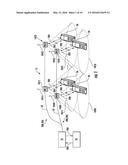 | 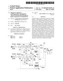 |
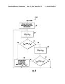 | 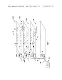 |
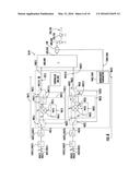 | 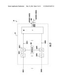 |
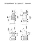 | 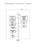 |
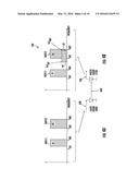 | 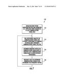 |
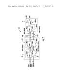 |
| Similar patent applications: | |
| Date | Title |
|---|---|
| 2015-11-12 | Frequency hopping sequence generation |
| 2015-12-03 | Fast acquisition frequency detector |
| 2016-01-07 | Wireless feedback system and method |
| 2016-01-28 | Method and system for modulation-independent carrier phase recovery |
| 2016-04-07 | Apparatus and method for quadrupling frequency of reference clock |
| New patent applications in this class: | |
| Date | Title |
|---|---|
| 2016-05-12 | Receiving apparatus and demodulation method |
| 2015-05-28 | Wireless network receiver |
| 2015-05-21 | Frequency-shift keying receiver |
| 2015-04-16 | Hart sampling |
| 2014-01-23 | Receiving apparatus and method in smart utility network communication system |
| Top Inventors for class "Pulse or digital communications" | |
| Rank | Inventor's name |
|---|---|
| 1 | Marta Karczewicz |
| 2 | Takeshi Chujoh |
| 3 | Shinichiro Koto |
| 4 | Yoshihiro Kikuchi |
| 5 | Takahiro Nishi |