Patent application title: SHELVING STRUCTURE
Inventors:
Pao-Hsun Tang (Lu-Kang Chen, TW)
IPC8 Class: AA47B9602FI
USPC Class:
211134
Class name: Supports: racks shelf type
Publication date: 2016-05-05
Patent application number: 20160120313
Abstract:
A shelving structure has a frame member and a woven body. The frame
member has a rectangular shape and a respective connecting pipe disposed
at four corners thereof, and each connecting pipe is connected to a
supporting loop. An upper edge of the supporting loop is provided with a
first securing lip and a lower edge of the supporting loop is provided
with a second securing lip parallel to the first securing lip. A width of
the second securing lip is smaller than a width of the first securing
lip. The woven body has a shape corresponding to an enclosed space formed
by the connecting pipes and the supporting loop, and the woven body
extends from the second securing lip into the frame member and is welded
onto the first securing lip. The frame member is provided with a
plurality of supporting below the woven body.Claims:
1. A shelving structure comprising: a frame member having a rectangular
shape and a respective connecting pipe disposed at four corners thereof,
each connecting pipe connected to a supporting loop, an upper edge of the
supporting loop provided with a first securing lip and a lower edge of
the supporting loop provided with a second securing lip parallel to the
first securing lip, wherein a width of the second securing lip is
one-fourth to one-third of a width of the first securing lip; and a woven
body having a shape corresponding to an enclosed space formed by the
connecting pipes and the supporting loop, the woven body inserted from
the second securing lip and secured onto the first securing lip facing
the second securing lip.
2. (canceled)
3. The shelving structure as claimed in claim 1, wherein the frame member is provided with a plurality of supporting rods below the woven body.
Description:
BACKGROUND OF THE INVENTION
[0001] 1. Field of the Invention
[0002] The present invention relates to a shelving structure, and more particularly to a shelving structure having strong strength and low manufacturing cost.
[0003] 2. Description of the Related Art
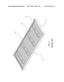
[0004] Currently, a typical shelving structure, as shown in FIGS. 5 and 6, includes a frame member 40 and a woven body 50, each of four ends of the frame member 40 is provided with a sleeve tube 41 which is individually welded onto four supporting loops 42. Furthermore, both an upper edge and an lower edge of the supporting loop 42 are individually provided with a extending lip 43 parallel with each other, and the woven body 50 is welded on to an inner side of the extending lip 43 of the upper edge of the supporting loop 42. For assembly, two adjacent supporting loops 42 need to be welded onto the sleeve tube 41 and the woven body 50 is placed between the two extending lips 43 of the two supporting loops 42, the other two supporting loops 42 are correspondingly secured to enclose the woven body 50, and then to complete the frame member 40, the woven body 50 is welded onto the other extending lips 43 of the corresponding frame members. However, the above-mentioned typical shelving structure has following problems: The complex assembly process causes higher defect rate and higher manufacture cost.
[0005] Therefore, it is desirable to provide a shelving structure to mitigate and/or obviate the aforementioned problems.
SUMMARY OF THE INVENTION
[0006] An objective of the present invention is to provide a shelving structure which is easy to manufacture and providing better steadiness.
[0007] In order to achieve the above mentioned objective, a shelving structure comprises a frame member and a woven body. The frame member has a rectangular shape and a respective connecting pipe disposed at four corners thereof, and each connecting pipe is connected to a supporting loop. An upper edge of the supporting loop is provided with a first securing lip and a lower edge of the supporting loop is provided with a second securing lip parallel to the first securing lip. A width of the second securing lip is smaller than a width of the first securing lip. The woven body has a shape corresponding to an enclosed space formed by the connecting pipes and the supporting loop, and the woven body extends from the second securing lip into the frame member and is welded onto the first securing lip facing the second securing lip. The frame member is provided with a plurality of supporting below the woven body.
[0008] In one objective of the present invention, the width of the second securing lip is 1/3 or 1/4 of the width of the first securing lip, therefore, the woven body can be easily placed into the frame member from the second securing lip. Furthermore, the edge of the woven body contacts the side of the first securing lip facing the second securing lip and also is welded onto the woven body to be secured onto the first securing lip. Since the second securing lip is narrower than the first securing lip, it is easy to perform the welding procedure.
[0009] Furthermore, in another objective of the present invention, the frame member is provided with the plurality of supporting rod below the woven body correspondingly perpendicular to the second securing lip of the supporting loop, to enhance the strength of the frame member and improve the pressurization strength of the woven body. Therefore, the frame member and the woven body require less material, and an efficient welding area between the first securing lip and the woven body provides strong support around the woven body.
[0010] Other objects, advantages, and novel features of the invention will become more apparent from the following detailed description when taken in conjunction with the accompanying drawings.
BRIEF DESCRIPTION OF THE DRAWINGS
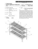
[0011] FIG. 1 is a perspective drawing of a preferred embodiment according to the present invention.
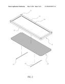
[0012] FIG. 2 is an exploded view of the embodiment according to the present invention.
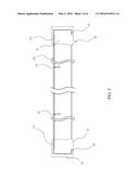
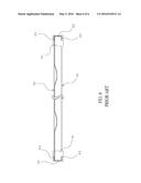
[0013] FIG. 3 is a cross-sectional view of the embodiment according to the present invention.
[0014] FIG. 4 is a schematic drawing of the embodiment according to the present invention.
[0015] FIG. 5 is a perspective drawing of a typical shelving structure. FIG. 6 is a cross-sectional view of the typical shelving structure.
DETAILED DESCRIPTION OF THE PREFERRED EMBODIMENT
[0016] Please refer to FIGS. 1, 2 and 3. A shelving structure comprises a frame member 10 and a woven body 20. The frame member 10 has a rectangular shape and a respective connecting pipe 11 disposed at four corners thereof, and each connecting pipe 11 is connected to a supporting loop 12. An upper edge of the supporting loop 12 is provided with a first securing lip 13 and a lower edge of the supporting loop 12 is provided with a second securing lip 14 parallel to the first securing lip 13. A width of the second securing lip 14 is smaller than a width of the first securing lip 13, and preferably the width of the second securing lip 14 is 1/4 to 1/3 of the width of the first securing lip 13. The woven body 20 has a shape corresponding to an enclosed space formed by the connecting pipes 11 and the supporting loop 12, and the woven body 20 extends from the second securing lip 14 into the frame member 10 and is welded onto the first securing lip 13 facing the second securing lip 14. The frame member 10 is provided with a plurality of supporting 15 below the woven body 20. The supporting rod 15 enhances the strength of the frame member 10 and improves the pressurization strength of the woven body 20. Moreover, the second securing lip 14 is narrower than the first securing lip 13, it is easy to perform the welding procedure. Therefore, the frame member 10 and the woven body 20 require less material.
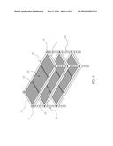
[0017] Please refer to FIG. 1 to FIG. 3 again. All of the connecting pipes 11 at the four corners of the frame member 10 are connected to the supporting loop 12, and the first securing lip 13 and the second securing lip 14 perpendicularly extend from the upper edge and the lower edge of the supporting loop 12. The width of the second securing lip 14 is 1/3 or 1/4 of the width of the first securing lip 13, therefore, the woven body 20 can be easily placed into the frame member 10 from the second securing lip 14. Furthermore, the edge of the woven body 20 contacts the side of the first securing lip 13 facing the second securing lip 14 and also is welded onto the woven body 20 to be secured onto the first securing lip 13. Since the second securing lip 14 is narrower than the first securing lip 13, it is easy to perform the welding procedure. Furthermore, the frame member 10 is provided with the plurality of supporting rod 15 below the woven body 20 correspondingly perpendicular to the second securing lip 14 of the supporting loop 12, to enhance the strength of the frame member 10 and improve the pressurization strength of the woven body 20. Therefore, the frame member 10 and the woven body 20 require less material, and an efficient welding area between the first securing lip 13 and the woven body 20 provides strong support around the woven body 20. Please refer to FIG. 4. A plurality of shelving structures of the embodiment and four standing rods 30 are combined by placing the standing rods 30 through the connecting pipe 11 of the frame member 10, to complete a storage shelve.
[0018] Although the present invention has been explained in relation to its preferred embodiment, it is to be understood that many other possible modifications and variations can be made without departing from the spirit and scope of the invention as hereinafter claimed.
User Contributions:
Comment about this patent or add new information about this topic:
Images included with this patent application:
 |  |
 |  |
 |  |
 |
| Similar patent applications: | |
| Date | Title |
|---|---|
| 2015-04-09 | Shelving structure |
| 2016-02-11 | Combined shelf structure |
| 2016-03-10 | Shelf support structure |
| 2015-11-19 | A rack assembly structure |
| New patent applications in this class: | |
| Date | Title |
|---|---|
| 2016-06-30 | Frame structure of storage basket |
| 2016-06-16 | Riser deck |
| 2016-06-09 | Spill containing refrigerator shelf assembly |
| 2016-04-21 | A storage unit |
| 2016-03-17 | Divider for shelfing and method and system for dividing a shelf |
| Top Inventors for class "Supports: racks" | |
| Rank | Inventor's name |
|---|---|
| 1 | Stephen N. Hardy |
| 2 | Wen-Tsan Wang |
| 3 | Gregory M. Bird |
| 4 | Shane Obitts |
| 5 | Kaveh Didehvar |