Patent application title: ICE MAKER
Inventors:
Yunho Jung (Gyeonggi-Do, KR)
IPC8 Class: AF25C100FI
USPC Class:
62340
Class name: Refrigeration means producing shaped or modified congealed product
Publication date: 2015-10-22
Patent application number: 20150300716
Abstract:
An ice maker is disclosed. The ice maker includes: an ice-making room S1
having a module for producing and keeping ices; a machine room S2
including a first pump 45 circulating ice-making water and a condenser 73
cooling a refrigerant; and a condenser cooling system 80 disposed close
to the condenser 73, in which the condenser cooling system 80 includes: a
humidifying module 81 disposed close to the condenser 73; a cooling water
storage 82 disposed under the humidifying module 81 and connected with a
water level control pipe 29 connected to the ice-making room S1; a
discharger 83 connected to the cooling water storage 82 through a valve
831; and a second pump 84 supplying cooling water in the cooling water
storage 82 to the humidifying module 81 through a cooling water
circulation pipe 85.Claims:
1. An ice maker comprising: an ice-making room S1 having a module for
producing and keeping ices; a machine room S2 including a first pump 45
circulating ice-making water and a condenser 73 cooling a refrigerant;
and a condenser cooling system 80 disposed close to the condenser 73,
wherein the condenser cooling system 80 includes: a humidifying module 81
disposed close to the condenser 73; a cooling water storage 82 disposed
under the humidifying module 81 and connected with a water level control
pipe 29 connected to the ice-making room S1; a discharger 83 connected to
the cooling water storage 82 through a valve 831; and a second pump 84
supplying cooling water in the cooling water storage 82 to the
humidifying module 81 through a cooling water circulation pipe 85.
2. The ice maker of claim 1, further comprising a controller that closes the valve 831 in an ice-making process so that the second pump 84 circularly supplies cooling water in the cooling water storage 82 to the humidifying module 81, that opens the valve 831 before an ice-separating process so that the cooling water in the cooling water storage 82 is discharged outside, and that closes the valve 831 in the ice-separating process so that ice-separating water overflowing the water level control pipe 29 flows into the cooling water storage 82.
3. The ice maker of claim 2, wherein the humidifying module 81 includes: a spray pipe 811; and a cooling pad 812 disposed under the spray pipe 811 and functioning as a separator so that cooling water sprayed from the spray pipe 811 can flow in a zigzag shape.
4. The ice maker of claim 3, wherein a porous spray pad 813 is disposed between the spray pipe 811 and the cooling pad 812.
5. The ice maker of claim 1, wherein a cooling fan 74 is disposed close to the condenser 73.
Description:
TECHNICAL FIELD
[0001] The present invention relates to an ice maker, and more particularly, to an ice maker in which cooling efficiency of a condenser is improved.
BACKGROUND ART
[0002] An ice maker is a device continuously producing ices in a predetermined shape. Ice makers are generally used at home, restaurants, cafes, and the like. An ice maker is largely composed of an ice-making room for producing and keeping ices and a machine room where a cooling system for circulating a refrigerant and cooling is disposed.
[0003] The refrigerant requires exchanging heat well through the machine room for smooth operation of the ice maker. An air cooling type using a cooling fan and a water cooling type using water are used to increase the efficiency of heat exchange in the machine room.
[0004] The air cooling type makes it difficult to replace a filter and remove dirt for the feature of ice makers installed in small spaces, while the water cooling type wastes a large amount of water. Accordingly, it is required to develop a new type of ice maker supplementing these drawbacks.
[0005] There are Korean Patent Application Publication Nos. 10-2001-0051251 and 10-2006-0036986 in relation with an ice maker.
DISCLOSURE
Technical Problem
[0006] The present invention is directed to providing an ice maker of which a condenser has improved cooling efficiency by using ice-separating water at 5 to 9° C., which has been wasted by overflowing a water level control pipe, for cooling the condenser.
[0007] Further, the present invention provides an ice maker capable of keeping cooling a condenser with clean and cold cooling water by continuously supplying cooling water to a humidifying module by circulating cooling water in a cooling water storage, draining the cooling water in the cooling water storage before ice-separating, and receiving new cooling water through a water level control pipe in ice-separating.
[0008] Further, the present invention provides an ice maker capable of sweeping up dirt on a humidifying module by sending cooling water down through the humidifying module.
Technical Solution
[0009] One aspect of the present invention provides an ice maker that includes: an ice-making room S1 having a module for producing and keeping ices; a machine room S2 including a first pump 45 circulating ice-making water and a condenser 73 cooling a refrigerant; and a condenser cooling system 80 disposed close to the condenser 73, in which the condenser cooling system 80 includes: a humidifying module 81 disposed close to the condenser 73; a cooling water storage 82 disposed under the humidifying module 81 and connected with a water level control pipe 29 connected to the ice-making room S1; a discharger 83 connected to the cooling water storage 82 through a valve 831; and a second pump 84 supplying cooling water in the cooling water storage 82 to the humidifying module 81 through a cooling water circulation pipe 85.
[0010] Further, the ice maker may further include a controller that closes the valve 831 in an ice-making process so that the second pump 84 circularly supplies cooling water in the cooling water storage 82 to the humidifying module 81, that opens the valve 831 before an ice-separating process so that the cooling water in the cooling water storage 82 is discharged outside, and that closes the valve 831 in the ice-separating process so that ice-separating water overflowing the water level control pipe 29 flows into the cooling water storage 82.
[0011] Further, the humidifying module 81 may include: a spray pipe 811; and a cooling pad 812 disposed under the spray pipe 811 and functioning as a separator so that cooling water sprayed from the spray pipe 811 can flow in a zigzag shape.
[0012] Further, a porous spray pad 813 may be disposed between the spray pipe 811 and the cooling pad 812.
Advantageous Effects
[0013] According to the present invention, for an ice maker, it is possible to improve efficiency of cooling a condenser by using ice-separating water at 5 to 9° C., which has been wasted by overflowing a water level control pipe, for cooling the condenser.
[0014] Further, according to the present invention, for an ice maker, it is possible to keep cooling a condenser with clean and cold cooling water by continuously supplying cooling water to a humidifying module by circulating cooling water in a cooling water storage, draining the cooling water in the cooling water storage before ice-separating, and receiving new cooling water through a water level control pipe in ice-separating.
[0015] Further, according to the present invention, for an ice maker, it is possible to sweep up dirt on a humidifying module by sending cooling water down through the humidifying module.
DESCRIPTION OF DRAWINGS
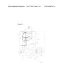
[0016] FIG. 1 is a diagram illustrating a cross-sectional configuration of an ice maker according to an exemplary embodiment of the present invention.
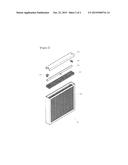
[0017] FIG. 2 is an exploded perspective view of a humidifying module according to an exemplary embodiment of the present invention.
BEST MODE
[0018] According to an aspect of the present invention, there is provided an ice maker that includes: an ice-making room S1 having a module for producing and keeping ices; a machine room S2 including a first pump 45 circulating ice-making water and a condenser 73 cooling a refrigerant; and a condenser cooling system 80 disposed close to the condenser 73, in which the condenser cooling system 80 includes: a humidifying module 81 disposed close to the condenser 73; a cooling water storage 82 disposed under the humidifying module 81 and connected with a water level control pipe 29 connected to the ice-making room S1; a discharger 83 connected to the cooling water storage 82 through a valve 831; and a second pump 84 supplying cooling water in the cooling water storage 82 to the humidifying module 81 through a cooling water circulation pipe 85.
MODES OF THE INVENTION
[0019] Hereinafter, preferred embodiments of the present invention will be described in detail with reference to the accompanying drawings, but those are provided only for explaining the present invention for those skilled in the art to easily achieve the present invention and the spirit and scope of the present invention are not limited thereto.
[0020] FIG. 1 is a diagram illustrating a cross-sectional configuration of an ice maker according to an exemplary embodiment of the present invention and FIG. 2 is an exploded perspective view of a humidifying module according to an exemplary embodiment of the present invention.
[0021] An ice maker 100 according to an embodiment includes: an ice-making room S1 having a module for producing and keeping ices; a machine room S2 including a first pump 45 circulating ice-making water and a condenser 73 cooling a refrigerant; and a condenser cooling system 80 disposed close to the condenser 73, in which the condenser cooling system 80 includes: a humidifying module 81 disposed close to the condenser 73; a cooling water storage 82 disposed under the humidifying module 81 and connected with a water level control pipe 29 connected to the ice-making room S1; a discharger 83 connected to the cooling water storage 82 through a valve 831; and a second pump 84 supplying cooling water in the cooling water storage 82 to the humidifying module 81 through a cooling water circulation pipe 85.
[0022] The ice maker 100 of the present embodiment is characterized by cooling the condenser 73, using ice-separating water, which has been wasted by overflowing the water level control pipe 29 from the ice-making room S1 in the past, and water melting out of a bin 50 as cooling water.
[0023] Further, in an ice-making process by the ice maker 100 of the present embodiment, the cooling water in the cooling water storage 82 is circularly supplied to the humidifying module 81. Thereafter, before an ice-separating process, it is circularly supplied to the humidifying module 81, temperature increases and cooling water with foreign substances is discharged out of the cooling water storage 82. Thereafter, ice-separating water overflowing the water level control pipe 29 in the ice-separating process and water produced by melting of ices in the bin 50 are kept in the cooling water storage 82 and used as new cooling water. Accordingly, clean and cold cooling water can always be kept in the cooling water storage 82 and supplied to the humidifying module 81. Therefore, it is possible to increase efficiency of cooling the condenser 73 and flush dirt in the humidifying module 81.
[0024] The ice maker 100 of the present embodiment includes the configuration of other common ice makers, so the basic operation principle and configuration of those ice makers will be described first and then the technical features of the ice maker 100 of the present embodiment will be described.
[0025] 1. Common Principle of Ice Maker
[0026] The ice maker 100 is a device basically continuously producing ices in a predetermined shape (for example, a cube). Ices produced in a predetermined shape are automatically kept in the bin 50 of the ice-making room S1. This is the difference from a refrigerator maintaining a specific temperature.
[0027] Similar to common ice makers, the ice maker 100 of the present embodiment includes: the ice-making room S1 for producing and keeping ices; and the machine room S2 where the first pump 45 for circulating ice-making water and the cooling system for circulating a refrigerant and cooling are disposed.
[0028] The ice maker 100 produces ices in a predetermined shape by repeating the ice-making process and the ice-separating process.
[0029] As for the ice-making process first, an ice-making frame 30 is disposed at the upper portion in the ice-making room S1. The ice-making frame 30 is open at the bottom and closed at the top, corresponding to the shape of desired ices. A plurality of ice-making frames 30 is sequentially arranged.
[0030] An evaporator 32 is coupled to the ice-making frame 30. The evaporator 32 is a pipe and a low-temperature refrigerant cools the ice-making frame 30 while flowing through the evaporator 32 in the ice-making process. Accordingly, the surface of the ice-making frame 30 is maintained at a low temperature of 10° C. or less. In contrast, in the ice-separating process, a high-temperature refrigerant flows through the evaporator 32 and increases the surface temperature of the ice-making frame 30.
[0031] A tub 20 is disposed under the ice-making frames 30. Water in the tub 20 is supplied upward to the ice-making frames 30 through a spray nozzle 26 by the first pump 45. The water sprayed to the ice-making frames 30 through the spray nozzle 26 is called `ice-making water`. When the ice-making water is sprayed to the ice-making frames 30 in the ice-making process, some of the ice-making water sticks to the surface of the ice-making frames 30 under zero degrees and rapidly changes into ice and the other of the ice-making water drops back into the tub 20.
[0032] When ice sufficiently grows on the ice-making frames 30, heat transfer from the evaporators 32 to the ice-making frames 30 decreases. That is, the temperature difference between the refrigerant flowing into the evaporator 32 and the refrigerant flowing out of the evaporator 32 is not large. For example, in the process (ice-making process) in which ice continuously grows on the ice-making frame 30, the temperature of the refrigerant flowing into the evaporator 32 is about -20° C. and the temperature of the refrigerant flowing out of the evaporator 32 is about -5° C. (temperature difference of 15° C.), but when a sufficient amount of ice grows on the ice-making frame 30, heat exchange does not occur any more, so the temperature of the refrigerant flowing into the evaporator 32 is about -20° C., while the temperature of the refrigerant flowing out of the evaporator 32 is about -15° C. (temperature difference of 5° C.). The temperature difference is detected by a temperature sensor (not illustrated) and a controller (not illustrated) determines that ice has been sufficiently made and stops the ice-making process.
[0033] When the ice-making process is finished, the ice-separating process of separating the ice on the ice-making frames 30 from the ice-making frames 30 is started.
[0034] The ice-separating process is carried out by putting a high-temperature refrigerant from an ice-separating pipe (a') into the evaporators 32 by controlling a valve V2 above the ice-making frames 30 with the controller (not illustrated), and supplying ice-separating water supplied from the outside of the ice-making frames 30 through a raw water supply pipe 40. The ice-separating water is common water at a room temperature. The surface temperature of the ice-making frames 30 is increased by heat supplied from the ice-separating water and the high-temperature refrigerant supplied to the upper portion of the ice-making frames 30, and the ice on the inner sides of the ice-making frames 30 melts. As time passes, the ice that has melted on the inner sides of the ice-making frames 30 comes off the ice-making frames 30 and fall by gravity. The falling ices are kept into the bin 50 through an incliner 27 that is a net or a combination of horizontal members.
[0035] Meanwhile, the ice-separating water supplied through the raw water supply pipe 40 is kept into the tub 20 through holes h of the ice-making frames 30. The amount of the ice-separating water (water flowing into the tub 20 through the raw water supply pipe 40) in the ice-separating process is larger than the amount of ices produced in the ice-making process (ices coming out into the bin 50). That is, the amount of the inflow ice-separating water is larger than the water coming out into the bin 50 as ices. Accordingly, in the related art, some of ice-separating water overflowed and was then discharged through the water level control pipe 29. The ice-separating water was cold at 5 to 9° C., because it flowed into the tub 20 in contact with the ice-making frames 30 under zero degrees.
[0036] In the present invention, the low-temperature ice-separating water that has been wasted through the water level control pipe 29 is used for cooling the condenser 73. This technical feature of the present invention will be described below.
[0037] After the ice-separating process is finished, the ice-making process is started again.
[0038] The machine room S2 is used to supply a low-temperature refrigerant in the ice-making room S2 to the evaporators 32 through a refrigerant pipe (a) or supply a high-temperature refrigerant to the evaporators 32 through the ice-separating pipe (a'). It is possible to select the temperature of a refrigerant to be supplied to the evaporators 32 by determining that it is the ice-separating process or the ice-making process and then controlling the valve V2 using the controller (not illustrated).
[0039] The high-temperature refrigerant that is supplied to the ice-separating pipe (a') has passed through a compressor 71, but not through the condenser 73, so it is at high temperature and high pressure. On the other hand, the refrigerant that is supplied through the refrigerant pipe (a) has passed through the compressor 71, the condenser 73, and a capillary tube 76, so it is at low temperature and low pressure.
[0040] Although the ice-separating pipe (a') of the machine room S2 and the ice-separating pipe (a') of the ice-making room S1 are separated in FIG. 1 for making the configuration simple, they are actually connected to each other. Further, the refrigerant pipe (a) of the machine room S2 and the refrigerant pipe (a) of the ice-making room S1 are also connected to each other.
[0041] 2. Technical Features of the Present Invention
[0042] A technical feature of the present invention is to use low-temperature ice-separating water that has been wasted through the water level control pipe 29 in the past and ice water melting in the bin 50 to cool the condenser 81 by supplying them to the condenser cooling system 80.
[0043] The condenser cooling system 80 includes: a humidifying module 81 disposed close to the condenser 73; a cooling water storage 82 disposed under the humidifying module 81 and connected with a water level control pipe 29 connected to the ice-making room S1; a discharger 83 connected to the cooling water storage 82 through a valve 831; and a second pump 84 supplying cooling water in the cooling water storage 82 to the humidifying module 81 through a cooling water circulation pipe 85.
[0044] The humidifying module 81 may be composed of a spray pipe 811 and a cooling pad 812 disposed under the spray pipe 811 and having guides so that cooling water sprayed from the spray pipe 811 can flow in a zigzag shape.
[0045] A porous spray pad 813 may be disposed between the spray pipe 811 and the cooling pad 812.
[0046] Cooling water is supplied to the cooling pad 812 through the spray pipe 811 of FIG. 2. Since the cooling pad 812 has the continuous zigzag guides, when cooling water is supplied to the top, it flows down along the guides. The cooling water can remain in the cooling pad 812 as long as possible by the zigzag guides. The guides may be made of paper such as a corrugated cardboard, or may be made of metal, plastic, or fiber. Air can pass through the front and rear of the cooling pad 812. Air passing through the cooling pad can take appropriate water from the cooling water and is sufficiently cooled by the cooling water at about 9° C. Accordingly, when the air that has passed through the cooling pad 812 passes through the condenser 73, the efficiency of cooling the condenser 73 is improved. Further, since the cooling water flows down in the cooling pad 812, dirt and foreign substances are removed down. Accordingly, the cooling pad 812 can be kept clean.
[0047] In the air cooling type of the related art, a filter is attached to a side of the condenser 73, so dirt collects on the filter while air taken inside by a cooling fan 74 flows through the filter. When the dirt is not periodically removed, efficiency of the condenser 73 decreases. In the ice maker 100 of the present embodiment, since dirt is always removed, so deterioration of the efficiency of the condenser due to dirt is prevented.
[0048] Since the porous spray pad 813 is disposed between the spray pipe 811 and the cooling pad 812, cooling water sprayed from the spray pipe 811 is supplied and distributed well to the cooling pad 812.
[0049] The cooling water storage 82 is coupled to the bottom of the humidifying module 81. The cooling water dropping through the humidifying module 81 is kept in the cooling water storage 82. When the second pump 84 is operated, cooling water is continuously supplied to the humidifying module 81 through the cooling water circulation pipe 85. The cooling water storage 82 is connected with the water level control pipe 29, so it is periodically supplied with the ice-separating water overflowing the water level control pipe 29 (called "cooling water", when it flows in the cooling water storage 82) in the ice-separating process.
[0050] It is preferable to discharge the cooling water in the cooling water storage 82 through the discharger 83, before the ice-separating water flows into the cooling water storage 82 in the ice-separating process. Accordingly, the cooling water storage 82 can always keep clean cooling water. A valve 831 is disposed between the discharger 83 and the cooling water storage 82.
[0051] The process that the ice-separating water flows into the cooling water storage 82, is used as cooling water, and continuously supplied to the humidifying module 81 can be automatically performed by the controller. The controller (not illustrated) closes the valve 831 in the ice-making process so that the cooling water in the cooling water storage 82 is circularly supplied to the humidifying module 81 by the second pump 84.
[0052] The controller discharges the cooling water in the cooling water storage 82 to the outside by opening the valve 831 before the ice-separating process. Since the cooling water right before the ice-separating process has been circulated several times and supplied to the humidifying module 81, it has increased in temperature to the room temperature and includes a lot of dirt and foreign substances. The cooling water contaminated at the room temperature is wasted right before the ice-separating process.
[0053] The controller closes the valve 831 in the ice-separating process so that the ice-separating water overflowing the water level control pipe 29 newly flows into the cooling water storage 82. As the ice-separating water newly flowing inside through the water level control pipe 29 is kept in the cooling water storage 82 and the used as cooling water, it is possible to always supply low-temperature clean cooling water to the humidifying module 81.
[0054] The cooling fan 74 is disposed close to the condenser 73. The cooling fan 74 can take air inside so that external air can be supplied to the condenser 73 through the humidifying module 81. The cooling fan 74 may be disposed to push air so that external air is supplied to the condenser 73 through the humidifying module 81, if necessary.
[0055] Although exemplary embodiments of the present invention were described above, they are just examples and claims of the present invention are not limited thereto. Equivalent changes and modification by those skilled in the art should be construed as being included in the scope of the present invention.
INDUSTRIAL APPLICABILITY
[0056] The present invention can be used as a device for making ices.
User Contributions:
Comment about this patent or add new information about this topic:
Images included with this patent application:
 |  |
 |
| New patent applications in this class: | |
| Date | Title |
|---|---|
| 2016-03-31 | Freezer air tower and damper |
| 2016-03-17 | Freezer, in particular ultra-low temperature freezer |
| 2016-02-25 | Ice maker assembly and refrigerator appliance |
| 2016-02-11 | Pipe freezer system |
| 2016-01-21 | Refrigerator |
| Top Inventors for class "Refrigeration" | |
| Rank | Inventor's name |
|---|---|
| 1 | Michael F. Taras |
| 2 | Alexander Lifson |
| 3 | Koji Yamashita |
| 4 | Hiroyuki Morimoto |
| 5 | Patrick J. Boarman |