Patent application title: METHOD OF CARRYING OUT ABSORPTION/DISTILLATION IN A SINGLE COLUMN DESIGN
Inventors:
Manish Bhargava (Katy, TX, US)
Joseph C. Gentry (Houston, TX, US)
IPC8 Class: AF25J306FI
USPC Class:
Class name:
Publication date: 2015-07-30
Patent application number: 20150211790
Abstract:
Embodiments of the invention are directed to a process wherein two
different unit operations (absorption and distillation) take place on
either side of a top dividing wall column. One side of the dividing wall
column uses absorption to separate non-condensable components from the
feed; the other side of the dividing wall uses distillation to separate
heavier liquid components.Claims:
1. A distillation column comprising a wall in a top section of the column
having two condensers.
2. The top dividing wall column of claim 1, wherein the two condensers are a partial condenser and a total condenser.
3. The top dividing wall column of claim 1 having a first side and a second side, wherein the first side contains an absorption unit for separation of lighter non-condensable components and the second side contains a distillation unit for separation of heavier liquid components.
4. The top dividing wall column of claim 1, wherein the column is used as a stabilizer that removes non condensable lighter components from mix aromatics feed.
5. The top dividing wall column of claim 1, wherein the column is used as a deheptanizer that removes non condensable lighter components from mix aromatics feed.
6. The top dividing wall column of claim 1, wherein the first side contains an absorption solvent.
7. The top dividing wall column of claim 3, wherein the distillation unit on the second side generates a bottom product that is sent back to the first side as an absorption medium for removal of lighter non condensable components.
8. The distillation column of claim 7, wherein the reflux of the bottom product reduces loss of C5/C6 to vapor.
Description:
CROSS-REFERENCES TO RELATED APPLICATIONS
[0001] This application claims the benefit under 35 U.S.C. §119(e) of U.S. Provisional Patent Application No. 61/931,440 filed Jan. 24, 2014 which is incorporated herein by reference in its entirety as if fully set forth herein.
FIELD OF THE INVENTION
[0002] Partial condensers are used in distillation columns when the distillate product is removed as a vapor stream. This approach is commonly employed when there are very light, i.e., volatile components in the feed to the column that would require a high column pressure and a low condenser temperature to completely condense these very volatile components. The use of a partial condenser can avoid the use of costly refrigeration in the condenser. Many distillation schemes with partial condensers have both liquid and vapor products. In such cases there is considerable spillover of heavier components in the vapor product and vice versa. It is not possible to maintain a sharp split between liquid and vapor products in conventional partial condensation schemes. This drawback can be overcome by use of a top dividing wall column, which uses both absorption and distillation techniques on either side of dividing wall to provide a sharp split between vapor and liquid components.
BACKGROUND OF THE INVENTION
[0003] There are several distillation schemes in aromatics complex that use partial condenser for separation of lighter components. Typical examples of such columns include a C5 stabilizer or a dehepatnizer column.
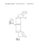
[0004] FIG. 1 represents the prior art system of a conventional C5 stabilizer. This conventional stabilizer aims at separating C1-C4 components as an overhead vapor product, C5 as an overhead liquid product and C6+ components as the bottoms product of the column. The column operates at 8.5 kg/cm2g with an overhead temperature of 40° C.
[0005] However, the prior art system possesses several disadvantages. It is not possible to condense the lighter components in the overhead product at 8.5 kg/cm2g and use cooling water as the overhead cooling media. The overhead system has a partial condenser. Lighter components (used as offgas) are drawn as the vapor product from the partial condenser. C5 product is the liquid stream from the partial condenser. A considerable amount of C5 components are lost to the offgas vapor stream. The loss of C5 components can be prevented by decreasing the overhead temperature (e.g., by using refrigeration) or increasing the column pressure. However, this increases the operating cost of the column. The prior art systems provides a loose split between C1 to C4 in vapor and C5 in liquid product, the recoveries of these components is also low as they are lost in the off gas vapor stream.
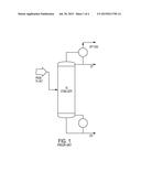
[0006] FIG. 2 represents the prior art system of a conventional dehepatnizer column. This conventional dehepatnizer aims at separating lighter components (C1 to C5) as an overhead vapor product, C7 as an overhead liquid product and C8+ components as the bottoms product of the column. The column operates at 5.0 kg/cm2g with an overhead temperature of 40° C.
SUMMARY OF THE INVENTION
[0007] An embodiment of the invention is directed to a process wherein two different unit operations (absorption and distillation) take place on either side of a top dividing wall column. One side of the dividing wall column uses absorption to separate non-condensable components from the feed; the other side of the dividing wall uses distillation to separate heavier liquid components.
BRIEF DESCRIPTION OF THE DRAWINGS
[0008] FIG. 1 represents a conventional C5 stabilizer in accordance with the prior art;
[0009] FIG. 2 represents a conventional dehepatnizer column in accordance with the prior art;
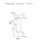
[0010] FIG. 3 represents a process scheme in accordance with an embodiment of the invention for a stabilizer design; and
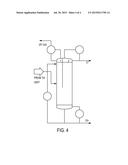
[0011] FIG. 4 represents process scheme in accordance with an embodiment of the invention for a deheptanizer design.
DETAILED DESCRIPTION OF EXEMPLARY EMBODIMENTS
[0012] An embodiment of the invention is directed to a process wherein two different unit operations (absorption and distillation) take place on either side of a top dividing wall column.
[0013] In an embodiment of the invention shown in FIG. 3, the process scheme of the claimed invention is designed to separate light components (non condensable), C5 (Top liquid product), and C6+ (Heavies) in a single top divided column. The feed stream is first sent to the pre-fractionation side of the top divided column. The vertical dividing wall splits the top portion of the column into two halves. The feed side of the wall is called the pre-fractionation section. The non-condensables (used as off gas) is removed as overhead vapor product from a vent condenser. In certain embodiments of the invention, the column overhead pressure is set at 2.7 kg/cm2g via a pressure controller on the overhead vapor product line. The section above the feed acts as an absorption section that is primarily used to minimize the loss of heavier components. The pre-fractionation side has reflux coming from two sources: A liquid stream condensed from a vent condenser; and a heavy stream from a bottoms pump.
[0014] In an embodiment of the invention, the vapor from the overhead of the main section is condensed and cooled to 40° C. in air-cooled exchanger followed by the water-cooled condenser. The condenser outlet is collected in an overhead receiver. The C5 liquid is pumped out of the drum via reflux pumps. A portion of the light liquid is sent back to the column as reflux and the remainder is withdrawn as C5 product.
[0015] In an embodiment of the invention, the temperature in top section of the main column is controlled in cascade with the reflux flow control loop. This allows control over the quality of the C5 product by suppressing the tendency of the heavier components from going to the top of the column.
[0016] In an embodiment of the invention, the reboiler connected to the main section is a thermosyphon steam reboiler that uses steam as heating medium. The heat input to the reboiler is regulated by controlling the steam flow cascaded to the column bottom tray temperature controller.
[0017] The C5 bottom product is controlled by a level control loop in cascade with the bottom product flow rate.
[0018] Table 1 presents a comparison of operational parameters between the conventional stabilizer design and the TDWC stabilizer design of the claimed invention.
TABLE-US-00001 TABLE 1 Stabilizer Conventional design of the Operational Parameters Units Design invention C5 in product Kg/hr 367 659 Operating Pressure Kg/cm2g 8.3 2.7 RVP Psia 107 27 Overhead temperature ° C. 40 40 Duty MMkcal/hr 4.7 4.7 (integrated with HAC Overhead) C5 recovery Wt % 52.3% 96.8% C5 purity Wt % 59.1% 90.4% Benzene in C5 product Wt % 0.1% 0.1% Bottoms temperature ° C. 229 183
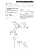
[0019] FIG. 4 represents a process scheme in accordance with an embodiment of the invention for a deheptanizer design. The column pressure is reduced to 1.8 kg/cm2g. GT-Low pressure deheptanizer reduces the energy consumption by 19%.
[0020] Table 2 presents a comparison between the conventional deheptanizer design and the TDWC stabilizer design of the claimed invention.
TABLE-US-00002 TABLE 2 Stabilizer Conventional design of the Operational Parameters Units Design invention Operating Pressure Kg/cm2g 5 1.8 Overhead temperature ° C. 40 40 Duty Mmkcal/hr 23.3 18.9 Bottoms temperature ° C. 227 193
[0021] Overall aspects of the invention relate to methods for increasing the energy efficiency or better product purities in a distillation process using a top divided column. Those having skill in the art, with the knowledge gained from the present disclosure, will recognize that various changes could be made to the methods disclosed herein without departing from the scope of the present invention. Mechanisms used to explain theoretical or observed phenomena or results, shall be interpreted as illustrative only and not limiting in any way the scope of the appended claims.
User Contributions:
Comment about this patent or add new information about this topic:
Images included with this patent application:
 |  |
 |  |
 |
| New patent applications in this class: | |
| Date | Title |
|---|---|
| 2022-09-08 | Shrub rose plant named 'vlr003' |
| 2022-08-25 | Cherry tree named 'v84031' |
| 2022-08-25 | Miniature rose plant named 'poulty026' |
| 2022-08-25 | Information processing system and information processing method |
| 2022-08-25 | Data reassembly method and apparatus |
| New patent applications from these inventors: | |
| Date | Title |
|---|---|
| 2022-07-21 | Hexane as a by-product of isomerization unit using a dividing wall column |
| 2015-10-08 | Process for recovering isoprene from pyrolysis gasoline |
| 2014-08-21 | Separation processes using divided columns |
| 2014-04-10 | Processes and systems for obtaining aromatics from catalytic cracking hydrocarbons |
| 2014-02-06 | Heavy hydrocarbon removal systems and methods |