Patent application title: Machine to Make, Store and Use Ice
Inventors:
Norman Davis (Estero, FL, US)
IPC8 Class: AF24F500FI
USPC Class:
Class name:
Publication date: 2015-07-09
Patent application number: 20150192314
Abstract:
The invention makes a solid block or blocks of ice, stores the ice where
it is made, and when needed consumes the ice as a heat sink for cooling
or refrigeration. The invention is directed at the market for reduction
of peak electric loads, by making ice at night when electric rates are
low and ambient temperatures cool, and using the ice for cooling during
the day in periods of high temperatures and high electric rates. Ice is
made/consumed by direct contact with the cooled/heated surface, giving
high heat transfer rates and efficiency. The basic concept is expressed
in a number of embodiments, allowing for a variety of uses in small to
extremely large applications.Claims:
1. A machine which a. Generates ice by means of a generating surface
cooled by Freon or other refrigerant, which generating surface is
repetitively detached a short distance from the previously frozen ice by
separating the generating surface and the frozen ice at a shallow angle
relative to the generating surface, which separation opens a gap between
the generating surface and the previously frozen ice, which gap is
simultaneously filled with water which immediately freezes, and by such
repetitive action generates a block of solid ice, and b. stores the ice
in situ, for later use, and c. when cooling is needed, consumes the ice
by redirecting the flow of refrigerant such that the machine receives
warm refrigerant from, for example, the heat exchanger of an air
conditioning system or the condenser of a refrigeration system, uses the
warm refrigerant to warm the generating surface, and forces the warm
generating surface against the ice, thereby quickly and efficiently
melting the ice and cooling the refrigerant, which refrigerant is then
returned for use in the air conditioning or refrigeration system, and
which d. incorporates sensors and controls, as necessary, in order to
interface with the air conditioning or refrigeration system to which it
is attached and to maximize the efficiency of the total system.
2. A machine as in claim 1 wherein said generating surface moves through a water-filled or air-filled vessel of cylindrical or prismatic shape, generating a block of solid ice behind it as it moves, and when cooling is needed consumes the ice by moving the warmer generating surface in the opposite direction, melting the ice by contact.
3. A machine as in claim 2 wherein said generating surface is in the form of the exterior of a cone which is detached from the frozen ice by withdrawing the generating surface from the face of the previously frozen ice, and for certain cone angles by simultaneously rotating the generating surface.
4. A machine as in claim 2 wherein the generating surface is in the form of a round flat circular plate which is detached from the frozen ice by simultaneously rotating and withdrawing the generating surface from the face of the previously frozen ice, and in which at the center of said circular plate there may be a cone, a heated section, or a small separately rotating flat circular plate.
5. A machine as in claim 2 wherein said generating surface is in the form of the exterior surface of a pyramid whose base is a square, rectangle or other polygon, and in which said generating surface is repetitively detached from the frozen ice by withdrawing the generating surface a short distance from the face of the previously frozen ice.
6. A machine as in claim 2 wherein the generating surface is in the form of a flat plate which is detached from the frozen ice by moving sideways, across the face of the ice block, and simultaneously withdrawing from the ice block.
7. A machine as in claim 1 wherein the generating surface is in the form of the interior surface of a truncated cone or pyramid, which generating surface is fixed in the top or bottom of an air or water-filled insulating vessel of cylindrical or prismatic shape, and from which generating surface the frozen ice is repetitively detached by the action of a ram at the tip of the cone or pyramid, thus quickly and efficiently making a column of ice, and when cooling is needed quickly and efficiently generates cold refrigerant by progressively melting the ice block.
8. A machine as in claim 7 wherein the generating surface is in the form of the interior surface of a truncated cone, which generating surface is fixed in the bottom of an insulating vessel of cylindrical shape, and from which generating surface the frozen ice is repetitively detached by the action of a ram at the tip of the cone, which ram acts by first rotating, then pushing the ice block upwards, and then rotating as it is withdrawn, and which ram has a frontal surface in the form of a flat circular plate or a flat circular plate with a conical projection at its center.
9. A machine as in claim 7 wherein the generating surface is in the form of the interior of a truncated pyramid, which generating surface is fixed in the end of a vessel of prismatic shape, and from which generating surface the frozen ice is repetitively detached by the action of a circular ram at the tip of the pyramid, which ram acts by first rotating, then pushing the ice block upwards, and then rotating as it is withdrawn, and which ram has a frontal surface in the form of a flat circular plate or a flat circular plate with a conical projection at its center, and in which the edges of the pyramidal shape of the generating surface are tapered to the shape of a circle at the point at which it meets the circular ram.
10. A machine as in claim 2 wherein said generating surface is in the form of the interior of a truncated cone or pyramid, with a ram at the truncated end of the cone or pyramid, and in which said generating surface is repetitively detached from the frozen ice by withdrawing the generating surface from the face of the previously frozen ice while said ice is restrained from moving by the ram, which ram then withdraws.
11. A machine as in claim 10 wherein said generating surface is in the form of the interior of a truncated cone or pyramid, with a ram at the truncated end of the cone or pyramid, and in which said generating surface is repetitively detached from the frozen ice by first rotating the ram, then withdrawing the generating surface from the face of the previously frozen ice while said ice is restrained from moving by the ram, which ram then simultaneously rotates and withdraws, and which ram has a frontal surface in the form of a flat circular plate or a flat circular plate with a conical projection at its center.
12. A machine as in claim 1 wherein multiple generating surfaces of the type described in claim 9 are arranged in the form of a continuous horizontal grid which is fixed at the top or bottom of a water-filled tank, or at the bottom of an air-filled tank.
13. A machine as in claim 1 wherein two grids as described in claim 12 are fixed at the top and bottom of an air or water-filled tank.
14. A machine as described in claim 2 wherein multiple generating surfaces are connected to form a horizontal grid, which grid may move vertically within in a water-filled rectangular tank of any length and width, and in which said generating surfaces may be on the lower face of the grid, in which case the grid starts at the bottom of the tank and moves upward through the tank, generating a solid block of ice below the grid as it moves upward; or in which said generating surfaces may be on the upper surface of the grid, in which case the grid starts at the top of the tank and moves downward through the tank, generating a solid block of ice above the grid as it moves downward.
15. A machine with two horizontal grids of the type described in claim 12 which are fixed at the top and bottom of a water filled tank, and with multiple moving horizontal grids of the type described in claim 14 suspended in the tank, which arrangement would allow a tank of any height to be used.
16. A machine as in claim 14 wherein the individual generating surfaces are square or rectangular flat plates arranged in the form of a grid, with a small space between each plate and the adjacent plate, and in which the plates are moved in unison or are alternately moved, for instance with one half of the plates, in a pattern similar to the red squares on are checkerboard, being first moved, and then the remaining plates being moved, with the motion of each plate to be simultaneously lateral to and away from the previously formed ice surface such that the direction of motion of the individual plates is at a shallow angle to the surface of the previously formed ice, with the result that after all the plates have moved, the entire grid will have shifted laterally and away from the previously formed ice at a shallow angle, allowing the ice generation process to continue. The next lateral motion of the plates will be in the direction opposite to the previous motion, such that the overall pattern of motion of the grid will be a zigzag, with the net motion in a direction away from and perpendicular to the surface of the ice block.
17. A machine as in claim 14 wherein the individual generating surfaces are in the form of the exterior of a cone or of a square or rectangular pyramid, arranged in the form of a grid, and in which the generating surfaces are alternately retracted, for instance with one half of the surfaces being retracted from the previously formed ice, in a pattern similar to the red squares on a chessboard, and then the remaining surfaces being retracted.
18. A machine as in claim 14 wherein the individual generating surfaces are in the form of the interior of a truncated cone or pyramid, and from which generating surfaces the frozen ice is repetitively detached by the action of a circular ram at the tip of each pyramid, which ram acts by first rotating, then pushing the ice block upwards, and then rotating as it is withdrawn; and which ram has a frontal surface in the form of a flat circular plate or a flat circular plate with a conical projection at its center; and in which the edge of the pyramidal shape of each generating surface is tapered to the shape of a circle at the point at which it meets the circular ram; and in which all of said rams act in unison.
19. A machine as in claim 5, wherein the generating surface has a cross-section in the shape of the exterior of a V or of an inverted V, and in which said generating surface extends lengthwise within a water-filled trough of any length, and in which said generating surface is repetitively detached from the frozen ice by withdrawing the generating surface downwards a short distance from the face of the previously frozen ice.
20. A machine as in claim 5, wherein the generating surface has a cross-section in the shape of the exterior of a V, and in which said generating surface extends lengthwise within an air-filled trough of any length, and in which said generating surface is attached to a plate or beam which runs the length of the trough, and in which said beam and generating surface are moved vertically by a series of hydraulic cylinders or other means.
21. A machine as in claim 7 or claim 9, wherein the generating surface extends lengthwise and forms an elongated V-shaped trough, in the base of which V-shaped trough are a series of circular rams, which rams may be placed continuously or spaced along the length of said V-shaped trough, in such manner that the action of said rams and generating surface produce a continuous "wall" of ice.
22. A machine as in claim 10 or claim 11, wherein the generating surface extends lengthwise and forms an elongated V-shaped trough, in the base of which V-shaped trough are a series of circular rams, which rams may be placed continuously or spaced along the length of said V-shaped trough, and in which the generating surface together with the rams moves downward in an elongated tank in such manner that the action of said rams and generating surface produce a continuous "wall" of ice.
23. A generating surface as in claim 2, wherein said generating surface moves through a water-filled vessel of cylindrical or prismatic shape, generating a block of solid ice behind it as it moves.
24. A generating surface as in claim 3, wherein said generating surface is in the form of the exterior of a cone which is detached from the frozen ice by withdrawing the generating surface from the face of the previously frozen ice, and for certain cone angles by simultaneously rotating the generating surface.
25. A generating surface as in claim 4, wherein the generating surface is in the form of a round flat circular plate which is detached from the frozen ice by simultaneously rotating and withdrawing the generating surface from the face of the previously frozen ice, and in which at the center of said circular plate there may be a cone, a heated section, or a small separately rotating flat circular plate.
26. A generating surface as in claim 5, wherein said generating surface is in the form of the exterior surface of a pyramid whose base is a square, rectangle or other polygon and in which said generating surface is repetitively detached from the frozen ice by withdrawing the generating surface from the face of the previously frozen ice.
27. A generating surface as in claim 6, wherein the generating surface is in the form of a flat plate which is detached from the frozen ice by moving sideways, across the face of the ice block, and simultaneously withdrawing from the ice block.
28. A generating surface and ram as in claim 7, wherein the generating surface is in the form of the interior surface of a truncated cone or pyramid, which generating surface is fixed in the top or bottom of an air or water-filled insulating vessel of cylindrical or prismatic shape, and from which generating surface the frozen ice is repetitively detached by the action of a ram at the tip of the cone or pyramid, thus quickly and efficiently making a column of ice, and when cooling is needed quickly and efficiently generates cold refrigerant by progressively melting the ice block.
29. A generating surface and ram as in claim 8, wherein said generating surface is in the form of the interior of a truncated cone which generating surface is fixed in the bottom of an insulating vessel of cylindrical shape, and from which generating surface the frozen ice is repetitively detached by the action of a ram at the tip of the cone, which ram acts by first rotating, then pushing the ice block upwards, and then rotating as it is withdrawn, and which ram has a frontal surface in the form of a flat circular plate or a flat circular plate with a conical projection at its center.
30. A generating surface and ram as in claim 9, wherein said generating surface is in the form of the interior of a truncated pyramid, which generating surface is fixed in the end of a vessel of prismatic shape, and from which generating surface the frozen ice is repetitively detached by the action of a circular ram at the tip of the pyramid, which ram acts by first rotating, then pushing the ice block upwards, and then rotating as it is withdrawn, and which ram has a frontal surface in the form of a flat circular plate or a flat circular plate with a conical projection at its center, and in which the edges of the pyramidal shape of the generating surface are tapered to the shape of a circle at the point at which it meets the circular ram.
31. A generating surface and ram as in claim 10, wherein said generating surface is in the form of the interior of a truncated cone or pyramid and in which said generating surface is repetitively detached from the frozen ice by withdrawing the generating surface from the face of the previously frozen ice, while said ice is restrained from moving by a ram, which ram then withdraws.
32. A generating surface and ram as in claim 11, wherein said generating surface is in the form of the interior of a truncated cone or pyramid and in which said generating surface is repetitively detached from the frozen ice by withdrawing the generating surface from the face of the previously frozen ice, while said ice is restrained from moving by a ram, which ram then simultaneously rotates and withdraws, and which ram has a frontal surface in the form of a flat circular plate or a flat circular plate with a conical projection at its center.
33. A generating grid as in claim 12, wherein multiple generating surfaces of the type described in claim 9 are arranged in the form of a continuous horizontal grid which is fixed at the top or bottom of a water-filled tank, or at the bottom of an air-filled tank.
34. A generating grid as in claim 14, wherein multiple generating surfaces are connected to form a horizontal grid, which grid is supported in a water-filled flat tank of any length and width, and in which said generating surface may be on the lower surface of the grid, which grid moves upward through the tank, in which case a solid block of ice is formed below the grid as it moves upward, or in which said generating surface may be on the upper surface of the grid, which grid moves downward through the tank, in which case a solid block of ice is formed above the grid as it moves downward.
35. A generating grid as in claim 16, wherein the individual generating surfaces are square or rectangular flat plates arranged in the form of a grid, with a small space between each plate and the adjacent plate, and in which the plates are moved in unison or are alternately moved, for instance with one half of the plates, in a pattern similar to the red squares on are checkerboard, being first moved, and then the remaining plates being moved, with the motion of each plate to be simultaneously lateral to and away from the previously formed ice surface such that the direction of motion of the individual plates is at a shallow angle to the surface of the previously formed ice, with the result that after all the plates have moved, the entire grid will have shifted laterally and away from the previously formed ice at a shallow angle, allowing the ice generation process to continue. The next lateral motion of the plates will be in the direction opposite to the previous motion, such that the overall pattern of motion of the grid will be a zigzag, with the net motion in a direction away from and perpendicular to the surface of the ice block.
36. A generating grid as in claim 17, wherein the individual generating surfaces are square or rectangular pyramids arranged in the form of a grid, with a small space between each surface and the adjacent surface, and in which the generating surfaces are moved in unison or are alternately moved, for instance with one half of the surfaces being moved away from the previously formed ice, in a pattern similar to the red squares on are checkerboard, and then the remaining surfaces being moved, with the motion of each generating surface to be perpendicular to the plane of the grid, allowing the ice generation process to continue.
37. A ram as in claim 8, which rotates as it is withdrawn.
38. A ram as in claim 8, which acts by first rotating, then pushing the ice block upwards, and then rotating as it is withdrawn.
Description:
A. INTRODUCTION
[0001] At the present time there is a significant benefit to end users in reducing the use of electricity during periods of high demand, when electric rates are at their highest level. Numerous systems are currently being employed for this purpose. Some of these involve the use of ice, in which ice is generated during the night, when electric rates are low, and consumed during times of peak rates to improve the efficiency and reduce the electric usage of refrigeration and air conditioning systems. The scale of these systems varies dramatically. Some are for use by very small entities, such as a small commercial building, while others are on a very large scale. The proposed invention, in its various embodiments, could be scaled to a wide range of sizes.
[0002] This invention is a machine which quickly and efficiently makes ice, stores the ice, and when needed quickly and efficiently consumes the ice to provide a heat-sink for refrigeration or air conditioning use, or for other purposes. The invention, in various embodiments, generates ice in a manner which has very high heat transfer rates and high efficiency, stores the ice until needed, and then, using the same surface which generated the ice, consumes the ice as a heat sink for refrigeration or air conditioning systems or for other purposes, again with very high heat transfer rates and high efficiency.
[0003] All prior patents related to the proposed invention have extruded ice from a conical or pyramidal cell, which ice was removed from the cell for use elsewhere. In particular, U.S. Pat. No. 2,671,465 describes the basic mechanism of such a device, and U.S. Pat. No. 2,639,594 describes a machine which operated successfully. Both of these patents apply only to the production of ice to be used away from the machine, both apply only to the use of a generating surface in the form of the interior of a cone or pyramid, and both rely on the linear action of a specific type of ram to force the ice block away from the refrigerated surface.
[0004] Throughout this narrative and the claims, the surface referred to as the "generating surface" or the "ice generating surface" both freezes and melts the ice, depending on need. The term "refrigerant" is herein used to mean a heat transfer fluid, such as Freon, and which may be cooling or heating the generating surface depending on whether the machine is making ice or melting ice.
[0005] The descriptions and illustrations which follow refer in general to machines which generate ice in vertical configurations. Many of these machines could be made to generate ice in a horizontal configuration, by making various obvious modifications to the designs.
[0006] The drawings and explanations contained herein should be considered to be illustrative and should not be construed so as to in any way limit the claims made. In particular, the methods of rotation and linear action of the generating surface and the ram can be achieved in various ways not shown. The term pyramid or pyramidal as used here should be taken to refer to a pyramid with a base which is a square, rectangle or other polygon. The size of the ram has been exaggerated in the drawings for purposes of clarity.
B. NOVEL ELEMENTS OF THE INVENTION
[0007] The novel elements supporting this invention are 1) a number of different designs for the rapid and efficient production of solid ice by a refrigerated generating surface, 2) use of the same surface which makes the ice to rapidly and efficiently consume the ice as a heat sink for refrigeration, air conditioning or other use, 3) the efficient combining these two functions by storing the ice where it has been generated, and 4) the design of the ram used in certain embodiments of the invention. The use of these elements in a single machine is the basis for Claims 1 through 22.
C.1 GENERATION OF ICE
[0008] Ice which is generated by contact with a cold surface generally forms a sufficiently strong bond with the cold surface that if the ice and the surface are pulled apart in tension the bonds within the ice may rupture preferentially to the bonds between the ice and the cold surface, leaving significant amounts of ice bonded to the cold surface. Successful extrusion of ice depends upon separating the ice from the cold surface at a shallow angle. If the angle of separation is sufficiently small, shearing forces predominate over tensile forces, and the ice separates cleanly, leaving a gap. If this gap is small, and is immediately filled with water, the water will freeze quickly on contact with the refrigerated surface, and the process can be repeated. It has been demonstrated that a machine of this type can produce ice at a rate of 130 kg of ice per square meter of freezing surface per hour.
[0009] In all of the following designs the expansion which takes place when water freezes is accommodated at the freezing surface, and does not generate pressure on the walls of the containing vessel.
C.2 STORAGE OF ICE
[0010] The machines described herein make a solid block of ice, either by repetitively moving the ice block away from a stationary generating surface or by moving the generating surface away from the stationary ice block. When an ice block of the desired volume has been made, it is stored in situ until needed for cooling.
[0011] In some of the following embodiments the vessel which stores the ice also contains the water used in the system. This has the advantage that a separate storage tank is avoided. Also, this arrangement permits the making of ice above the stored water, as the buoyancy of the ice will hold it in the top of the vessel. In order to prevent freezing of the stored water, the stored water is maintained at a temperature slightly above 0° C. This has the additional advantage that all of the stored water is at the ideal temperature to be introduced at the ice generating surface.
[0012] In all embodiments in which the water and ice block are contained within the same vessel, an auxiliary storage tank will be required to accommodate a portion of the stored water as it is forced out of the vessel due to expansion of the ice as it freezes.
C.3 CONSUMPTION OF ICE
[0013] To consume the ice, the flow of refrigerant through the system is reversed, so that the ice block serves as a heat sink for air conditioning or refrigeration. In this mode, warm refrigerant is circulated through the generating surface, consuming the ice which is in contact with it. The ice and the generating surface are forced together, producing very rapid heat transfer into the ice. When all of the ice has been consumed, the machine is ready to generate ice again. In many of the embodiments herein, consumption of the ice block can be expedited by constructing the containing vessel so that refrigerant can also be circulated through the walls of the vessel during the consumption phase of the cycle.
[0014] In some of the following embodiments, to promote consumption it is necessary to provide a means by which the ice block is forced against the warm generating surface. In these cases a rigid plate is provided which is maintained in contact with the ice block. During ice production, force is applied to this plate only in those embodiments in which the ice block might float, and in that case only sufficient force is applied to offset the buoyancy of the ice block. During ice consumption a ram forces the plate against the ice block, which force maintains the ice block in intimate contact with the warm generating surface.
[0015] In some of the following embodiments, the vessel or tank in which the ice is made also holds the water supply for the system. In all of these cases the water circulates in the area of the ice blocks. A key advantage of this feature is that during the consumption phase of the cycle this water may be circulated through a heat exchanger in order to accelerate the rate of consumption.
D. DESCRIPTION OF NOVEL METHODS OF MAKING AND CONSUMING ICE BY AN INCREMENTALLY MOVING GENERATING SURFACE
[0016] Certain of the embodiments of this invention employ a generating surface which moves in incremental steps of a few millimeters through a water-filled or air-filled vessel of cylindrical or prismatic shape, leaving behind it a block of solid ice. This concept of ice generation is novel, and is the basis for Claim 2. The generating surfaces in the following embodiments are designed in such a way that when the generating surface is withdrawn, shear forces predominate over tensile forces so that the generating surface is cleaned of residual ice, and can thus quickly generate a new layer of ice in the small gap left by the withdrawal of the generating surface. In all of these embodiments the water which is to be introduced into contact with the freezing surface is maintained at a temperature close to 0° C. so that it will freeze quickly.
[0017] In these embodiments, the moving generating surface also serves to consume the ice when the machine is in the ice consumption mode, by forcing the warm generating surface against the ice block.
[0018] In some of these embodiments, a portion of the ice block is permanent. The surfaces of the vessel surrounding the permanent ice block are refrigerated, and the sides of the vessel and attachments to it are made in such manner that this permanent ice block is restrained from moving.
[0019] The following are descriptions of specific embodiments with incrementally moving generating surfaces.
D.1 Incrementally Moving Generating Surface in the Form of the Exterior of a Cone, with Optional Rotation of the Generating Surface
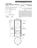
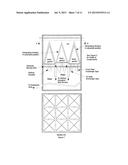
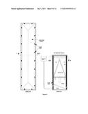
[0020] FIG. 1 is a sketch of a machine which uses the exterior of a conical surface for the making and consumption of ice. In the ice making mode, the generating surface moves through a cylindrical vessel, leaving ice behind it. The key elements of the machine are an insulated drum, with a conical piston which moves vertically and, if necessary, rotates, in the drum. The drum has horizontal corrugations and vertical guide rails which prevent the ice block, once formed, from moving. The elements of the piston are 1) the conical surface (the generating surface), 2) an internal cavity through which a refrigerant such as Freon circulates, 3) insulation covering the bottom of the cone. The piston is moved and rotated by mechanical or hydraulic means. The method shown here is illustrative only, by a rod attached to the base of the piston, which rod is attached to a hydraulic cylinder or other type of vertical actuator, and if necessary, to a rotational actuator. These actuators may be located either inside or outside of the drum. The space below the piston is filled with water. The space above the piston is filled with ice. The temperature of the ice is maintained by refrigerant coils which pass through the top of the ice block. The temperature of the conical surface is maintained by refrigerant passing through the interior of the piston. An expansion tank is provided to allow for expansion as water is converted to ice. Not shown is the heat exchanger which would supply cold or warm refrigerant to the machine depending on whether the machine is in ice making or ice consuming mode. Temperature sensors could be placed within the ice and water, and at points on the generating surface, to control or study the process. This design is the basis of Claim 3.
[0021] Prior to making ice, the piston is in the position shown, and the entire drum is filled with water. To initiate operation, the chamber above the piston is refrigerated by the refrigerant lines and by cooling the conical surface. Expansion of the freezing ice is accommodated by water passing through the annular space between the piston and the drum, and by allowing the piston to move downward. Once made, the ice block is maintained at a few degrees below 0° C. This block is never again consumed.
[0022] For making ice, the temperature of the generating surface is maintained below 0° C. The piston is moved downward a few millimeters, and rotated if necessary for proper separation. Note that horizontal corrugations in the drum and the shape of the ice block keep the surface of the ice in compression as the piston is withdrawn. The ice shears from the cone, creating a gap which is simultaneously filled with water from below the piston. Since the water forms a thin layer against the cooled generating surface, the water freezes very quickly. Once the this new layer is frozen, the temperature sensors on the cooling surface record a quick drop in temperature, signaling to the system controls that the piston may be dropped again, initiating a new freezing cycle. In practice, if the operating parameters are maintained constant, the cycle can be timer controlled at a constant rate, with no need for sensors. The cycle rate, and thus the rate of ice production, can be increased by lowering the temperature of the refrigerant.
[0023] The advantages of a conical surface over a flat surface are 1) a conical surface, depending on the angle of the cone, can be withdrawn from the ice surface without the need for rotation, 2) the lateral area of a cone is always greater than the area of its base, so the rate of ice production is greater than for a flat surface. If rotation is required, the rotation of the piston alternates from clockwise to counterclockwise in each consecutive action. This simplifies the design of the machine, and simplifies the design of the refrigerant lines feeding the generating surface.
[0024] FIG. 1 shows the cylinder in a vertical orientation, with ice formed above the piston. In practice, the cylinder can be in any orientation. The vertical position shown is somewhat advantageous as, ice being lighter than water, this orientation tends to prevent water from migrating into the ice-filled volume.
[0025] A generating surface which achieves separation by simultaneous rotation and withdrawal makes possible the use of a cone shape with a very low angle or of a flat circular plate. In this case it may be necessary to provide a small heated section or a small conical projection at the center of the cone or flat circular plate, to assist in separation. FIG. 2 shows this arrangement. This design is the basis of Claim 4.
[0026] In some instances it may be desirable to hold the water in a separate tank. In this case a configuration which is inverted from the position shown may be more advantageous. In the inverted configuration a small amount of water is maintained above the piston, so as to automatically fill the gap created by the generating surface as it withdraws.
D.2 Incrementally Moving Generating Surface in the Form the Exterior of a Pyramid
[0027] FIG. 3 illustrates a machine which utilizes a generating surface in the shape of the exterior of a pyramid. The generating surface moves through a cylindrical vessel, leaving ice behind it. This machine would function in generally the same manner as the previously described machine with a generating surface in the form of the exterior of a cone except that in this embodiment the generating surface cannot be rotated. This design is the basis for Claim 5.
[0028] In a variation of this design the ice block is at the bottom of an air-filled column, with the generating surface facing downward, and moving upward to make ice and downward to melt the ice.
D.3 Incrementally Moving Generating Surface in the Form of a Square or Rectangular Flat Plate
[0029] In this embodiment the ice generating surface is a flat plate which breaks its bond with the ice block by moving less than one centimeter to the side, and simultaneously withdrawing a few millimeters, allowing water to enter the gap created. In the next movement, the generating surface moves in the opposite direction. The general configuration of this embodiment is similar to that shown in FIG. 2, with a square or rectangular cross-section, and modified generating surface. This embodiment is the basis for Claim 6.
E.1 STATIONARY GENERATING SURFACE IN THE FORM OF THE INTERIOR OF A CONE, WITH A RAM OF NOVEL DESIGN AND OPERATION
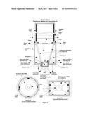
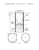
[0030] In these embodiments the ice generating surface is the interior of a stationary truncated cone fixed at the top or bottom of a vertical cylinder, with a refrigerated ram at the tip of the cone. The ice produced is pushed away from the generating surface into an insulated cylinder, where it is stored until needed. The novel elements in this machine consist of 1) storage of the ice as it is produced, in a vertical cylinder above or below the ice generating surface, 2) consumption of the ice using the same generating surface, and 3) the use of a flat ram or a flat ram with a conical projection at its center, which both rotates and moves linearly. Rotation of the ram allows it to more easily detach itself from the ice block than a ram which merely retracts, as in the prior art. Further, this ease of detachment from the ice block allows the ram itself to be refrigerated, which accelerates the overall freezing rate. This embodiment is the basis for Claim 8. This embodiment is shown in FIG. 4, with the cross-section labeled Conical Generating Surface.
[0031] To initiate the operation of the machine a block of ice is allowed to form, filling the volume above the cone. Then 1) the ram rotates a few degrees, to break the bond between the ram and the ice block, 2) the ram pushes the block of ice away from the generating surface, forming a gap between the ice and the ice generating surface, 3) the gap between the ice and the ice generating surface fills with water, 4) the ram rotates and retracts, detaching itself from the ice block, 5) additional water enters from the base of the cone, to fill the gap left by the retracting ram, 6) the water in the gap freezes, and the cycle is repeated until the desired quantity of ice has been generated. As shown in FIG. 4, the generating surface is at the bottom of the machine. The ice block moves up as it is formed, and the space above the ice block is air-filled.
[0032] The following embodiments envision storage of the water above or below the ice block. In these embodiments, if the open face of the generating surface is at the bottom of the machine and faces upward, then the water is stored above the ice, with an insulating blanket between the ice and the water. If the generating surface is at the top of the machine and faces downward, then the water is stored below the ice, also with an insulating blanket between the ice and the water. The advantages of these arrangements are 1) that separate storage for the water is not necessary, 2) that all of the water and ice are within the same insulated vessel, and 3) that a small amount of pressure on the water will hold the ice block against the surface of the ice generating surface, both during ice generation and consumption. A small amount of leakage between the water and the ice is not a problem, as the leakage will adhere to the ice block or drain into the water supply area for the ice generating surface. In the case in which the ice generating surface is at the top of the machine, a small pump may be necessary to maintain sufficient water pressure to assure that water fills the gap between the ice block and the generating surface in each cycle.
E.2 STATIONARY GENERATING SURFACE IN THE FORM OF THE INTERIOR OF A TRUNCATED PYRAMID WITH A SQUARE, RECTANGULAR OR POLYGONAL BASE, AND WHOSE TRUNCATED TIP IS SHAPED TO MEET A CIRCULAR RAM OF NOVEL DESIGN AND OPERATION
[0033] This embodiment is similar in design and operation to the previously described conical embodiment except that the ice generating surface has the form of a truncated pyramid, which generating surface is fixed in the end of a vessel of prismatic shape. In this embodiment the cross-section of the pyramid is gradually adjusted so as to make a smooth transition to a round cross-section where the pyramid meets the circular ram. This embodiment is the basis for Claim 9. This embodiment is shown in FIG. 4, with the cross-section labeled Pyramidal Generating Surface.
F. INCREMENTALLY MOVING GENERATING SURFACE IN THE FORM OF THE INTERIOR OF A CONE OR A PYRAMID WITH A SQUARE, RECTANGULAR OR POLYGONAL BASE, WITH A RAM
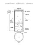
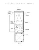
[0034] FIG. 5 shows a machine with a generating surface in the form of the interior of a truncated cone or pyramid. The truncated tip of the cone or pyramid contains a circular ram. As the ice generating surface is withdrawn from the face of the ice block, the ram maintains pressure on the end of the ice block, in order to keep the ice block in compression, and so prevent the ice block from moving or separating. To operate, the ram first rotates, then the ice generating surface is withdrawn, the ram is rotated and withdrawn from the ice block to its initial position, and the next cycle of ice generation begins. In those embodiments in which the ice generating surface is pyramidal, the cross-section of the pyramid is gradually adjusted so as to make a smooth transition to a round cross-section where the pyramid meets the circular ram. This embodiment is the basis for Claim 10 and Claim 11.
G. MULTIPLE GENERATING SURFACES IN THE FORM OF A HORIZONTAL GRID
[0035] To generate large volumes of ice, multiple flat, conical or pyramidal generating surfaces may be combined to make an array in the form of a grid. A number of different methods are described in the following. Some of these are shown in FIGS. 6,7 and 8. All of the following embodiments can be scaled to a vessel of any length and width. This is the basis for Claims 12 through 18.
[0036] In some of the following embodiments the individual ice blocks are kept separated. One method to maintain this separation is to constrain the end of each block from moving sideways. This can be done by making deep indentations, in the shape of the free ends of the ice blocks, in whatever surface contacts the ends of the ice blocks. In some cases the free ends of the ice blocks are at the end of the vessel. In other cases the free ends are supported by a moving insulated plate. Said moving insulated plate is held in place by hydraulic cylinders or other means, such that it exerts little force during the ice generation mode, but in the consumption mode forces the ice blocks against the generating surface so as to promote rapid consumption.
[0037] An alternate method of maintaining the separation between the ice blocks is to place vertical guide rails for the full height of the tank, between the ice generating surfaces. In those embodiments in which the ice block moves vertically, these rails could if necessary be heated to slightly above 0° C. during the melting phase, to prevent the ice block from adhering to the rails.
G.1 Multiple Generating Surfaces, Each in the Form of the Interior of a Cone or Pyramid, with Rams, Arranged in a Fixed Horizontal Grid at the Bottom of an Air-Filled Tank, at the Top or Bottom of a Water-Filled Tank, or at Both the Top and Bottom of a Water-Filled Tank
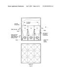
[0038] This embodiment is shown in FIG. 6. In this embodiment the individual ice blocks are kept separated as described above in Section G. This embodiment utilizes a horizontal grid of ice generating machines fixed in the bottom of an air-filled tank, with conical or pyramidal generating surfaces, in which the ice blocks move upward as they are generated, and with rams which act in unison. See FIG. 4 for detail of the individual ice generating machines. The generating surfaces operate in the manner described above in the section entitled "Stationary generating surface in the form of the interior of a truncated pyramid with a square, rectangular or polygonal base, and whose truncated tip is shaped to meet a circular ram of novel design and operation." The free ends of the ice blocks are supported as described above in "Rigid, insulated plate at the top of the ice blocks to support and separate the individual ice blocks."
[0039] A simple modification to this design would allow for the tank to be water-filled. In this case the grid supporting the generating surface can be located either at the bottom of the tank, generating an ice block which moves upward as it is generated, or at the top of the tank, generating an ice block which moves downwards.
[0040] These embodiments are the basis for Claim 12.
[0041] A further modification of this design employs a water-filled tank with stationary generating surfaces at both the top and bottom of the tank. This doubles the capacity of the machine while using the same floor area. This embodiment is the basis for Claim 13.
G.2 Multiple Generating Surfaces Attached to a Vertically Moving Horizontal Grid or Grids
[0042] In this embodiment a horizontal grid attached to multiple generating surfaces is suspended in a tank of water. In this embodiment the individual ice blocks are kept separated as described above in Section G. The grid moves vertically through a water-filled tank of any length and width, generating stationary blocks of ice as it moves. The generating surfaces may be on the lower face of the grid, in which case the grid starts at the bottom of the tank and moves upward through the tank, generating blocks of ice below the grid as it moves upward; or the generating surfaces may be on the upper surface of the grid, in which case the grid starts at the top of the tank and moves downward through the tank, generating blocks of ice above the grid as it moves downwards. This is the basis for Claim 14.
[0043] To consume the ice, warm refrigerant is circulated through the generating surfaces, while pressure is maintained on the entire grid to keep the warm surfaces in contact with the ice block. As the ice is consumed, the water produced passes through openings between the generating surfaces and returns to the water-filled part of the tank.
[0044] In a vessel shaped as a vertical column instead of a flat tank, any number of grids can be suspended in the water column, with stationary grids also at the top and bottom. The objective of this arrangement is to maximize the amount of ice generated per unit of area occupied by the tank. This is the basis for Claim 15.
G.2.a Multiple Generating Surfaces Attached to a Vertically Moving Horizontal Grid, with Each Generating Surface in the Form of a Square or Rectangular Flat Plate
[0045] In this embodiment the generating surfaces are flat plates attached to the top of a grid. Each generating surface can be moved by rams horizontally approximately one centimeter, and vertically a few millimeters. The grid is attached to the bottom of the tank with hydraulic cylinders or other linear actuators which are used only in the ice consumption mode. This embodiment is the basis for Claim 16.
[0046] Prior to operation, the grid is positioned near the top of the tank, and the water between the top of the tank and the generating surfaces is frozen. To begin operation, one-half of the plates, in a checkerboard pattern, are moved to the side and downward, separating the plates from the ice block at an angle of approximately 20 degrees. The resulting gap immediately fills with water, freezing within a few seconds. As soon as the new ice has sufficient strength, the remaining plates are moved in the same manner. The above steps are repeated, with the plates moving down and to the side in the reverse direction of the prior movement. At this point the horizontal actuators are at their starting position, and the vertical actuators have been retracted. To complete the cycle all of the vertical actuators are extended, which moves the grid downward and returns the grid and plates to their original relative positions. This is continued until the desired quantity of ice has been produced.
G.2.b Multiple Generating Surfaces Attached to a Vertically Moving Horizontal Grid, with Each Generating Surface in the Form of the Exterior of a Square or Rectangular Pyramid
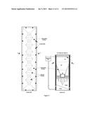
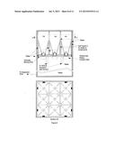
[0047] In this embodiment multiple generating surfaces are attached to a grid which is suspended in a tank of water, with the generating surfaces on the top of the grid, pointing upwards. Each generating surface is in the form of the exterior of a pyramid, as described above in the section entitled "Incrementally moving generating surface in the form of the exterior of a pyramid," and illustrated in FIG. 3. Each pyramid is connected to the top of the grid by a double-acting hydraulic cylinder or other actuator. Ice making commences at the top of the water-filled tank, and proceeds downward as ice is made. This arrangement is shown in FIG. 7.
[0048] Prior to operation, the grid is positioned at the top of the tank with all of the actuators extended, and the water between the top of the tank and the generating surfaces is frozen. To begin operation, half of the generating surfaces, in the pattern of the black squares of a chessboard, are withdrawn from the face of the ice block. As gaps form between the generating surfaces and the ice blocks, water fills the gap. Within a few seconds new ice forms in the space left by the withdrawn generating surfaces, and the remaining surfaces are withdrawn. At this point all of the actuators are extended simultaneously, moving the grid downward into position for a new cycle. This process continues until the desired quantity of ice has been produced.
[0049] In an alternative arrangement of this embodiment the generating surfaces are attached to the bottom of a vertically moving grid, with the grid initially located at the bottom of the tank and the generating surfaces pointing downwards. In this case the tank could be water-filled or air-filled.
[0050] The above embodiment is the basis for Claim 17.
G.2.c Multiple Generating Surfaces Attached to a Vertically Moving Horizontal Grid, with Each Generating Surface in the Form of the Interior a Cone or of a Pyramid with Square, Rectangular or Hexagonal Base, with a Ram
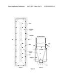
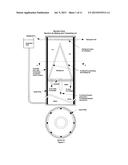
[0051] In this embodiment multiple generating surfaces are attached to the top of a grid which is suspended in a tank of water, as shown in FIG. 8. The individual ice blocks are kept separated as described above in Section G. The generating surfaces are on the top of the grid and open upwards, and have the form of the interior of an inverted truncated cone or of a pyramid with a square, rectangular or hexagonal base, as illustrated in FIG. 5, and in which the truncated tip of said cone or pyramid meets a ram. Said rams are of the type described in Section F above entitled "Incrementally moving generating surface in the form of the interior of a cone or a pyramid with a square, rectangular or polygonal base, with a ram." This embodiment is the basis for Claim 18.
[0052] Prior to operation, the grid is positioned at the top of the tank, and the water between the top of the tank and the generating surfaces is frozen. To begin operation, all of the rams are first rotated and then extended, pushing the entire grid downwards, and separating the ice blocks from the generating surfaces. As a gap forms between the generating surfaces and the ice blocks, water fills the gaps. Within a few seconds, new ice forms in the space left by the withdrawn generating surfaces. The rams are then simultaneously rotated and withdrawn, ice forms in this space, and a new cycle begins. This process continues until the desired quantity of ice has been produced.
H. LONGITUDINALLY EXTENDED GENERATING SURFACES WHICH GENERATE A BLOCK OF ICE OF ANY LENGTH
[0053] In the following embodiments the ice generating surface extends lengthwise within a trough of any desired length. In the cases in which the generating surface moves vertically, the generating surface is attached to a plate or beam which runs the length of the trough. The beam is moved by a series of hydraulic cylinders or other mechanism. Note that in the embodiments which employ rams, the design of the generating surface, and the placement and number of the rams may be varied considerably.
H.1 Elongated Moving Generating Surface with Cross-Section in the Form of an Inverted "V"
[0054] FIG. 9 illustrates an embodiment in which the generating surface has a cross-section in the form of the exterior of an inverted "V". The details of the design and operation of this embodiment are similar to those of the embodiment described in Section D.3 "Incrementally moving generating surface in the form of the exterior of a pyramid." This embodiment is the basis for Claim 19. As mentioned in Section D.3, this design may be inverted, with the generating surface in the form of the exterior of a "V". In this embodiment the ice block is made in the bottom of the trough, and the space above the ice block is air-filled. This embodiment is the basis for Claim 20.
H.2 Elongated Stationary Generating Surface with "V" Cross-Section and Rams
[0055] FIG. 10 illustrates an embodiment which is an elongated version of the embodiment described in FIG. 4 and Section E.2 "Stationary generating surface in the form of the interior of a truncated pyramid . . . " In this embodiment the generating surface forms the base of an elongated V-shaped trough, in which a solid elongated "wall" of ice is produced, and pushed up into the insulated space above the generating surface. In this embodiment multiple rams are employed. The configuration of the generating surface and of the rams may be either in the form shown in FIG. 10, Section BB or in FIG. 11, Section BB. The machine and the rams operate in generally the same manner as described above in Section E.2, with all rams acting in unison. This embodiment is the basis for Claim 21.
H.3 Elongated Moving Generating Surface with "V" Cross-Section and Rams
[0056] FIG. 11 illustrates this embodiment, which is an elongated version of the embodiment shown in FIG. 5, with Pyramidal Generating Surface, and as described in Section F. In this embodiment the cross-section of the elongated generating surface has the form of a "V". As the generating surface moves downward it leaves behind a solid elongated block of ice. The configuration of the generating surface and of the rams may be either in the form shown in FIG. 10, Section BB or in FIG. 11, Section BB. In this elongated embodiment the operating method is the same as in Section F, with all rams acting in unison. This embodiment is the basis for Claim 22.
DESCRIPTION OF FIGURES
[0057] FIG. 1. The machine in FIG. 1 consists of a cylindrical vessel with a piston which can move vertically through the vessel and also rotate. The conical surface (generating surface) of the piston is cooled or heated by refrigerant from an external heat exchanger. The space below the piston is filled with water. The space above the piston is filled with ice. To generate ice the conical surface is moved incrementally downward, and, if necessary, rotated, opening a small gap between the surface and the previously formed ice. This gap immediately fills with water and freezes, and the surface is again moved downward. To use the ice as a heat sink, the heat exchanger directs warm refrigerant to the generating surface, while upward pressure is maintained by the piston. As the ice melts it cools the refrigerant. Detailed operation is explained in Section D1 of the text.
[0058] FIG. 2. This figure shows a variation of the design shown in FIG. 1. In FIG. 2 the ice generating surface is a flat plate, with a conical center section. Operation is the same as in FIG. 1. Detailed operation is explained in Section D1 of the text.
[0059] FIG. 3. This figure shows a variation of the design shown in FIG. 1. In FIG. 3 the ice generating surface is a square pyramid. Operation is the same as in FIGS. 1 and 2, except in this case the generating surface does not rotate. Detailed operation is explained in Section D2 of the text.
[0060] FIG. 4. This figure shows a machine with a fixed generating surface in the shape of an inverted cone or rectangular pyramid. The conical (pyramidal) surface is cooled or heated by refrigerant from an external heat exchanger. At the base of the machine is a ram, also cooled or heated. Around the top and bottom of the conical (pyramidal) surface are means thru which water may be admitted to the interior of the cone (pyramid). Above the conical or pyramidal section of the machine is a tall drum which serves to hold in place the ice column which has been generated. Detailed operation is explained in Sections E1 and E2 of the text.
[0061] FIG. 5. In this embodiment the generating mechanism moves vertically within a drum of circular or rectangular cross-section. The moving mechanism contains the generating surfaces, a ram, and a connection to actuators which move the entire mechanism vertically, and move and rotate the ram. Detailed operation is explained in Section F of the text.
[0062] FIG. 6. This figure illustrates the use of multiple generating mechanisms combined into a grid. Each separate mechanism is similar to that employed in FIG. 4, labeled Pyramidal Generating Surfaces. The mechanisms are fixed to the bottom of a rectangular tank. The individual columns of ice generated are maintained in a vertical position by a vertically moving plate which restrains the tops of the columns. Detailed operation is explained in Section G and G1 of the text.
[0063] FIG. 7. This figure illustrates multiple generating mechanisms attached to a grid which moves vertically through a rectangular tank. The individual generating mechanisms are as illustrated in FIG. 4. Detailed operation is explained in Sections G, G.2 and G.2.b of the text.
[0064] FIG. 8. This figure illustrates multiple generating mechanisms attached to a grid which moves vertically through a rectangular tank. The individual generating mechanisms are as illustrated in FIG. 5. Detailed operation is explained in Sections G, G.2, and G.2.c of the text.
[0065] FIG. 9. This figure illustrates a machine with a longitudinally extended generating surface based on that shown in FIG. 3. Detailed operation is explained in Sections H and H.1 of the text.
[0066] FIG. 10. This figure illustrates a machine with a longitudinally extended generating surface based on that shown in FIG. 4. Detailed operation is explained in Sections H and H.2 of the text.
[0067] FIG. 11. This figure illustrates a machine with a longitudinally extended generating surface based on that shown in FIG. 5. Detailed operation is explained in Sections H and H.3 of the text.
User Contributions:
Comment about this patent or add new information about this topic:
Images included with this patent application:
 |  |
 |  |
 |  |
 |  |
 |  |
 |  |
| New patent applications in this class: | |
| Date | Title |
|---|---|
| 2022-09-08 | Shrub rose plant named 'vlr003' |
| 2022-08-25 | Cherry tree named 'v84031' |
| 2022-08-25 | Miniature rose plant named 'poulty026' |
| 2022-08-25 | Information processing system and information processing method |
| 2022-08-25 | Data reassembly method and apparatus |