Patent application title: ARCHERY BOW WITH COMPONENTS HAVING A CERAMIC COATING
Inventors:
Garrett L. Armstrong (Avon, NY, US)
IPC8 Class: AF41B510FI
USPC Class:
124 256
Class name: Spring bow compound bow
Publication date: 2014-03-27
Patent application number: 20140083401
Abstract:
Components and archery bows incorporating the same utilize coating layers
with compositions that comprise ceramic and ceramic-based materials. In
one embodiment, the coating layer is disposed on a wear surface of the
component, which can interpose the coating layer between the component
and a bowstring that moves relative to the component.Claims:
1. An archery bow, comprising: a cam assembly having a cam member with a
body that has a pivot axis and forms an annular groove disposed radially
about the pivot axis, wherein the body has a surface on which is disposed
a coating layer having a composition comprising a ceramic material.
2. The archery bow of claim 1, wherein the coating layer has a thickness of 30 μm or less.
3. The archery bow of claim 2, wherein the thickness is from 12 μm to about 25 μm.
4. The archery bow of claim 1, wherein the surface forms a groove surface on at least part of the annular groove.
5. The archery bow of claim 4, wherein the surface includes a first surface and a second surface disposed on opposing sides of the cam member.
6. The archery bow of claim 5, wherein the coating layer forms a monolithic layer over more than one of the groove surface, the first surface, and the second surface of the cam member.
7. The archery bow of claim 1, wherein the ceramic material comprises a polymer-ceramic matrix.
8. The archery bow of claim 1, further comprising a riser and a limb member secured to an end of the riser, the limb member securing to the first cam member at the pivot axis.
9. The archery bow of claim 8, further comprising a bowstring coupled to the first cam member to position at least part of the bowstring in the annular groove.
10. The archery bow of claim 8, further comprising a cable guard spaced apart from the riser, wherein the coating layer is interposed between the cable guard and the bowstring.
11. An archery bow, comprising: a riser having a first end and a second end; a first cam member and a second cam member, one each disposed on the first end and the second end of the riser, respectively, the first cam member and the second cam member comprising a pivot axis and an annular groove having a groove surface with a ceramic coating disposed thereon.
12. The archery bow of claim 11, wherein the ceramic coating is disposed on one or more surfaces found on a side of the first cam member and the second cam member.
13. The archery bow of claim 11, wherein the first cam member and the second cam member have an opening, and wherein the ceramic coating is disposed on a surface of the opening.
14. The archery bow of claim 11, further comprising a bowstring that contacts the groove surface.
15. The archery bow of claim 11, further comprising a cable guard and a set of power cables that extend between the first cam member and the second cam member, and wherein the cable guard comprises the ceramic coating.
16. A pulley for an archery bow, said pulley comprising: a body having an annular groove with a groove surface and a ceramic coating disposed on the groove surface.
17. The pulley of claim 16, wherein the ceramic coating has a material thickness of 30 μm or less.
18. The pulley of claim 16, wherein the ceramic coating comprises a polymer-ceramic matrix.
19. The pulley of claim 16, wherein the body has a first surface and a second surface disposed on opposing sides of the pulley, and wherein the ceramic coating is disposed on one of the first surface and the second surface.
20. The pulley of claim 19, wherein the coating layer forms a monolithic layer over more than one of the groove surface, the first surface, and the second surface of the pulley.
Description:
CROSS-REFERENCE TO RELATED APPLICATIONS
[0001] This application claims the benefit of priority to U.S. Provisional Patent Application Ser. No. 61/702,354, filed on Sep. 18, 2012, and entitled "Archery Equipment with Ceramic Coating." The content of this application is incorporated by reference herein in its entirety.
BACKGROUND
[0002] The subject matter disclosed herein relates to archery equipment and, in particular, to use of coatings and surface finishes on components found on archery bows.
[0003] Archery bows and, in particular, compound bows utilize many parts to transfer energy to a projectile. In conventional designs, these parts include a bowstring, flexible limbs, and a cam assembly (including cables and pulleys (or cams)). Integration of these parts provides mechanical advantage to an archer that draws back on the bowstring to prepare for a shot. The mechanical advantage allows for use of limbs of stiffer construction, which can store significantly more energy to deliver the projectile at higher speeds.
[0004] This design presents many challenges to construct parts that operate in compound bows. For example, many of these parts must mate together in assembled form, thereby requiring dimensions that are held within tight tolerances. These assemblies often induce relative motion between parts that can cause wear to occur, due to friction and other surface-to-surface contact. Moreover, the parts must be robust enough both to survive a wide range of operating conditions (e.g., wet, cold, hot, etc.) and to offer suitable visual appearance to avoid detection in the field.
[0005] In addition to material selection, manufacturers also employ surface treatments that can address one or more of these problems. These surface treatments include powder coats and wet spray paints, as well as material processes, e.g., anodizing, electroplating, etc. However, conventional use of these surface treatments can cause tolerance stack and undesirable wear on mating components. Traditional wet spray paints, for example, may require relatively thick layers to provide proper appearance. Unfortunately, the relative thickness of the resulting surface treatment impacts the dimensional tolerances of the parts, thus rendering the parts inappropriate for use in the archery bow.
BRIEF DESCRIPTION OF THE INVENTION
[0006] This disclosure describes improvements to components for archery bows to provide robust designs that maintain desired appearance for the component within specified dimensional constraints. Embodiments of the components, and the archery bows incorporating the same, utilize coating layers with compositions that comprise ceramic and ceramic-based materials. In one embodiment, the coating layer is disposed on a wear surface, which can interpose the coating layer between the component and a bowstring that moves relative to the component.
BRIEF DESCRIPTION OF THE DRAWINGS
[0007] Reference is now made briefly to the accompanying drawings, in which:
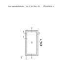
[0008] FIG. 1 depicts a schematic diagram of an exemplary embodiment of an archery bow component for use in archery bows;
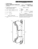
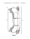
[0009] FIG. 2 depicts a perspective view of an example of an archery bow that incorporates the archery bow component of FIG. 1;
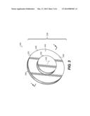
[0010] FIG. 3 depicts a perspective view of an exemplary embodiment of an archery bow component for use on the archery bow of FIG. 2;
[0011] FIG. 4 depicts a elevation cross-section view of the archery bow component of FIG. 3;
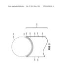
[0012] FIG. 5 depicts a detail view of the archery bow component of FIG. 4; and
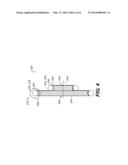
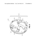
[0013] FIG. 6 depicts a perspective view of an exemplary embodiment of an archery bow component for use on the archery bow of FIG. 2.
[0014] Where applicable like reference characters designate identical or corresponding components and units throughout the several views, which are not to scale unless otherwise indicated.
DETAILED DESCRIPTION
[0015] FIG. 1 depicts a schematic diagram of an exemplary embodiment of an archery bow component 100 to illustrate use of coatings as part of the manufacture of archery bows. The archery bow component 100 includes a bow member 102 that has one or more surfaces including, for example, a wear surface 104 and one or more exposed surfaces 106. The archery bow component 100 also includes a coating layer 108 that is disposed on one or more of the surfaces 104, 106. The coating layer 108 has a material thickness 110 that defines the build-up of material on the surfaces 104, 106.
[0016] The bow member 102 can embody various parts found on archery bows. Examples of these parts include the sight, riser, quiver, and handle. However, this listing is not exhaustive. In one implementation, the parts can also include parts of a cam assembly, which helps to transfer energy in a bowstring to a projectile (e.g., an arrow). During operation, the bowstring can contact the coating layer 108, which may be interposed between the bowstring and the wear surface 104. This configuration affords the archery bow component 100 with a wear or bearing surface that may be less abrasive to the bowstring than the bare material of the bow member 102 present at the wear surface 104.
[0017] As noted herein, the coating layer 108 applies to the surfaces 104, 106 in a manner that does not unduly increase the overall dimensions of the archery bow component 100. These dimensions allow the archery bow component 100 to comport with manufacturing specifications for use as part of various assemblies in archery bows. In one implementation, the material thickness 110 of the coating layer 108 can have a value of about 30 μm or less, and, generally, may fall in a range of about 12 μm to about 25 μm.
[0018] The coating layer 108 can have a composition with constituent components that may include ceramics and/or ceramic-based materials. Examples of the constituent components can also include a polymer-ceramic matrix deposited from an organic suspension. Examples of polymers include polyformaldehyde and associated copolymers. Suitable organic solvents include 1-chloro-4-(trifluuoromethyl)-benzene, tert-butyl acetate, n-butyl acetate, ethanol, methyl ethyl ketone, phosphoric acid, and combinations thereof. Suitable ceramic compounds can include cadmium compounds including chromium oxide (CrO3), aluminum and aluminum compounds including aluminum oxide (Al2O3), silica (crystalline and/or amorphous), talc (Mg3H2(SiO3)4). In one embodiment, the composition of the coating layer 108 comprises a ceramic coating sold under the tradename CERAKOTE®, which is conventionally used to coat surfaces on firearms.
[0019] The composition may dictate the techniques to apply the coating layer to the surfaces 104, 106 of the archery bow component 100. These techniques can include various aerosol deposition methods (e.g., spray, sputter, etc.) and batch processes (e.g., dipping). Steps to heat and/or cool the coating layer 108 may prove useful to reduce cure time. These steps may also enhance operative characteristics (e.g., hardness) of the coating layer 108.
[0020] Selection of the application technique may also need to comport other physical characteristics for the coating layer 108. For example, the coating layer 108 may form a single continuous and/or monolithic layer over two or more of the surfaces 104, 106 on the bow member 102. On the other hand, certain configuration may necessitate that the coating layer 108 operate as one or more different layers, one each on the wear surface 104 and the surfaces 106. This disclosure also contemplates configurations of the archery bow component 100 in which the material thickness 110 of the coating layer 108 varies as between different values, e.g., for the wear surface 104 and the exposed surfaces 106.
[0021] Use of the coating layer 108 on the exposed surfaces 106 can prepare the archery bow component 100 for robust application on the archery bow. For example, the dimensional benefits of the coating layer 108 can accommodate for applications in which the exposed surfaces 106 may need to engage and/or assemble in close proximity to other surfaces on parts of the archery bow. The specification for these application may call out tight manufacturing tolerances that conventional coatings and/or surface treatments cannot satisfy with adequate quality assurances. In some applications, the coating layer 108 can modify the appearance of the archery bow component 100, both to provide coloring to the archery bow component 100 as well as to reduce glare and/or to provide matte finishes that do not reflect light.
[0022] FIG. 2 depicts a perspective view of an archery bow 112 that can incorporate an archery bow component (e.g., archery bow component 100 of FIG. 1). The archery bow 112 has a riser 114 with a handle 116. On either end of the riser 114, the archery bow 112 includes a limb element (e.g., a first limb element 118 and a second limb element 120) that support a cam assembly 122. Examples of the cam assembly 122 can include one or more cam members (e.g., a first cam member 124 and a second cam member 126) that couple with the limb elements 118, 120. The archery bow 112 also includes a cable guard 128 that couples with the riser 114. The cable guard 128 includes a cable retainer 130, which is spaced away from the riser 114 in the general direction of the limb elements 118, 120. As also shown in FIG. 1, the archery bow 112 can include a bowstring assembly 132 with one or more bowstrings (e.g., a draw string 134 and a set of power strings 136). The bowstrings 134, 136 can couple with the cam members 124, 126, with the set of power strings 136 extending proximate the cable retainer 130.
[0023] Broadly, the members of the archery bow 112 may utilize a coating layer (e.g., coating layer 108 of FIG. 1) of the composition disclosed herein. These members may include, for example, one or more of the cam members 124, 126 and the cable guard 128, each of which have surfaces that may contact the bowstrings 134, 136. The coating layer may be found interposed between the surfaces of these members and the bowstrings 134, 136. This configuration may help to reduce wear on the bowstrings 134, 136 during operation of the archery bow 112.
[0024] FIGS. 3, 4, and 5 illustrate schematic diagrams of an exemplary embodiment of an archery bow component 200, namely, a pulley 238 for use as a cam member (e.g., cam members 124, 126 of FIG. 2). In FIG. 3, the pulley 238 includes a body 240 with a pivot axis 242. The body 240 has a first side 244 and a second side 246 that can each have one or more surfaces 248. The body 240 also has one or more string engagement members (e.g., a first string engagement member 250 and a second string engagement member 252). The cross-section of FIG. 4, the string engagement members 250, 252 can each form a peripheral groove (e.g., a first peripheral groove 254 and a second peripheral groove 256) disposed about the pivot axis 242 to receive one or more bowstrings 234, 236 therein. As best shown in the detail view of FIG. 5, the peripheral grooves 254, 256 can have a groove surface 258 on which is disposed the coating layer 208. Configurations of the groove surface 258 can have a form factor in the shape of an arc and/or arcuate design to accommodate the bowstrings 234, 236. This disclosure does, however, contemplates other configurations for the form factor, e.g., square, rectangular, elliptical, etc.
[0025] Although found only on the groove surface 258, the coating layer 208 may be found on other surface of the pulley 238. For example, the coating layer 208 may be found on the surface 248 on one or more of the first side 244 and the second side 248. This construction may provide additional protection, as well as to afford the pulley 238 with certain surface coloration and/or finish that provides, as noted above, light reflecting and/or dissipating characteristics beneficial for use in the field.
[0026] FIG. 6 depicts a perspective view of an example of a pulley 338 that can also utilize a coating layer as disclosed and contemplated herein. The body 340 of the pulley 338 incorporates a series of openings 360 that expose a number of surfaces 362 in the body design. The techniques herein can dispose a coating layer (e.g., coating layer 108, 208 of FIGS. 1 and 5) on the surfaces 362, in addition to the surfaces 348 on the sides 344, 346.
[0027] In light of the foregoing, embodiments of the components discussed above incorporate materials, e.g., coating layers, that conform to dimensional and functional constraints typical of the various assemblies on archery bows. The coating layers are found on various surfaces of these components, including surfaces that would come into contact with the bowstrings found on the archery bows. This configuration of the coating layers can provide a wear surface that contacts in the bowstrings, which may reduce wear and/or abrasion that occurs as the bowstrings move relative to the components during operation of the archery bow.
[0028] As used herein, an element or function recited in the singular and proceeded with the word "a" or "an" should be understood as not excluding plural said elements or functions, unless such exclusion is explicitly recited. Furthermore, references to "one embodiment" of the claimed invention should not be interpreted as excluding the existence of additional embodiments that also incorporate the recited features.
[0029] This written description uses examples to disclose the invention, including the best mode, and also to enable any person skilled in the art to practice the invention, including making and using any devices or systems and performing any incorporated methods. The patentable scope of the invention is defined by the claims, and may include other examples that occur to those skilled in the art. Such other examples are intended to be within the scope of the claims if they have structural elements that do not differ from the literal language of the claims, or if they include equivalent structural elements with insubstantial differences from the literal language of the claims.
User Contributions:
Comment about this patent or add new information about this topic:
Images included with this patent application:
 |  |
 |  |
 |  |
 |
| Similar patent applications: | |
| Date | Title |
|---|---|
| 2014-02-13 | Archery bow limb dampening system |
| 2013-11-21 | Archery bowstring adjuster |
| 2013-08-01 | Archery bow limb bedding |
| 2010-04-01 | High entertaining ejecting toy |
| 2010-09-23 | Archery bow bracket |
| New patent applications in this class: | |
| Date | Title |
|---|---|
| 2016-09-01 | Compound bow |
| 2016-07-07 | Adjustable pulley assembly for a compound archery bow |
| 2016-06-23 | Archery bow limb support |
| 2016-06-16 | Illuminated archery bow sight apparatus |
| 2016-05-05 | Drawstring cocking assembly |
| Top Inventors for class "Mechanical guns and projectors" | |
| Rank | Inventor's name |
|---|---|
| 1 | Mathew A. Mcpherson |
| 2 | Richard L. Bednar |
| 3 | Michael J. Shaffer |
| 4 | Tetsuo Maeda |
| 5 | Jacob A. Hout |