Patent application title: Golf Training Device
Inventors:
Jeffrey Clifford Helstrom (Waconia, MN, US)
IPC8 Class: AA63B6936FI
USPC Class:
473270
Class name: Golf body movement or position indicator (e.g., stance aids, etc.) foot positioning aid
Publication date: 2013-06-06
Patent application number: 20130143686
Abstract:
A device that makes an imprint in a sand trap, providing a practicing
golfer with visual indications of proper swing path, club face angle,
club impact position, when making a basic sand shot.Claims:
1. A golf training device comprising a plurality of connected walls
constructed and arranged such that, when pressed into a bunker and
removed, said walls create a pattern showing stance alignment and swing
line.Description:
RELATED APPLICATIONS
[0001] This application claims priority to U.S. Provisional Application Ser. No. 61/567,521 filed Dec. 6, 2011 entitled Golf Training Device, which is hereby incorporated herein by reference in its entirety.
FIELD OF THE INVENTION
[0002] The invention relates to training devices for golf swings.
BACKGROUND OF THE INVENTION
[0003] There are hundred of swing trainers on the market. Unfortunately, swing trainers designed to teach a student how to make proper sand shots are almost non-existent. There exists a need for a device that can be used when learning how to perform golf shots from sand traps.
OBJECTS AND SUMMARY OF THE INVENTION
[0004] The invention provides a device that helps a golfer with alignment, club face angle, and proper club placement when hitting a golf ball out of the sand. The device makes an imprint in the sand that includes lines showing the golfer where to aim in relation to the flag, where the club should make initial contact with the sand relative to the ball, and how open the club face should be.
BRIEF DESCRIPTION OF THE DRAWINGS
[0005] These and other aspects, features and advantages of which embodiments of the invention are capable of will be apparent and elucidated from the following description of embodiments of the present invention, reference being made to the accompanying drawings, in which
[0006] FIG. 1 is a perspective view of a bottom of an embodiment of the invention;
[0007] FIG. 2 is a plan view of a bottom of an embodiment of the invention;
[0008] FIG. 3 is a depiction of a sand imprint made by an embodiment of the invention;
[0009] FIG. 4 is a diagram showing how an imprint made using an embodiment of the invention is used to align a golf shot; and
[0010] FIG. 5 is a plan view of a bottom of an embodiment of the invention.
DESCRIPTION OF EMBODIMENTS
[0011] Specific embodiments of the invention will now be described with reference to the accompanying drawings. This invention may, however, be embodied in many different forms and should not be construed as limited to the embodiments set forth herein; rather, these embodiments are provided so that this disclosure will be thorough and complete, and will fully convey the scope of the invention to those skilled in the art. The terminology used in the detailed description of the embodiments illustrated in the accompanying drawings is not intended to be limiting of the invention. In the drawings, like numbers refer to like elements.
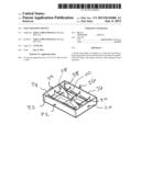
[0012] FIGS. 1 and 2 show an embodiment 10 of the invention. The device 10 is a stamp used to make an imprint in the sand of a sand trap. The embodiment 10 includes an open box like structure having four walls 20, 22, 24, and 26 arranged in a rectangle. A diagonal wall 28 extends through the device 10 from wall 20 to wall 24. Each of the walls has an edge 30, 32, 34, 36 and 38, respectively that will make an imprint when the device 10 is pressed into sand. The diagonal edge 38 includes a feature 40 that gives an indication in the resulting imprint as to where the golf ball should be placed when using the imprint to practice a sand shot. The feature 40 is shown as an interruption in the edge 38 but may be a variety of other features such as an intersecting edge forming a cross-hair design, a protrusion, or any other feature that would result in a visible indicator in the resulting sand imprint as to where the ball should be located. FIG. 2 includes dimensions for an example of an embodiment of the invention.
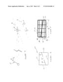
[0013] FIG. 3 shows a depiction of a sand imprint 100 made with the device 10. The imprint includes lines 50, 52, 54, 56, and 58 made by edges 40, 42, 44, 46, and 48 respectfully. Line 58 includes interruption 60 made by feature 40. When using the imprint, a ball should be placed on the interruption 60.
[0014] FIG. 4 shows an example of how the imprint 100 is used. The golfer places his or her feet F on a line A that runs parallel to the line 58. The line 58 represents the desired club path, extended in the Figure as line B, when making the sand shot. Lines 56 and 52 should be aligned with the flag 70. Thus, the club path B is to the left of the flag 70, for a right handed golfer. The leading edge of the golf club should be parallel to the line 54. Thus the club is considered to be "open." When swinging, the line 54 indicates where the club should first strike the sand. This ensures the club passes under the ball, allowing the sand to lift the ball out of the trap.
[0015] Having described some embodiments of the invention, the versatility of the invention may be discussed. For example, in addition to using the device 10 to make imprints 100 in sand, edges 32 and 36 may be coated with a substance, such as chalk, and used to assist in putting training. After coating the edges 32 and 36, and perhaps 34 as well, with chalk, the device 10 may be used to stamp a putting surface, thereby creating parallel chalk lines to be used as a visual aid for putting.
[0016] Additionally, devices may be constructed having different dimensions for different shots. For example, FIG. 5 shows a device 10 having the same components as those shown in the other Figures, except that the dimensions differ from those dimensions shown in FIG. 2. Altering these dimensions creates shots with slightly different ball flights. Additionally, it is to be understood that all of the embodiments shown in the figures are designed for right-handed golfers. Left-handed embodiments would simply be mirror-images of these embodiments. Another example of a variation of the device 10 would be a diagonal wall 28 that is adjustable such that it could be set at different angles for different shots.
[0017] Although the invention has been described in terms of particular embodiments and applications, one of ordinary skill in the art, in light of this teaching, can generate additional embodiments and modifications without departing from the spirit of or exceeding the scope of the claimed invention. Accordingly, it is to be understood that the drawings and descriptions herein are proffered by way of example to facilitate comprehension of the invention and should not be construed to limit the scope thereof.
User Contributions:
Comment about this patent or add new information about this topic:
Images included with this patent application:
 |  |
 |
| Similar patent applications: | |
| Date | Title |
|---|---|
| 2014-12-04 | Golf training device |
| 2014-09-18 | Ball travel-modifying device |
| 2014-12-04 | Golf putter practice device |
| 2014-12-18 | Golf teeing device |
| 2014-11-27 | Golf practice device |
| New patent applications in this class: | |
| Date | Title |
|---|---|
| 2015-11-05 | Systems and methods for training golf swings |
| 2014-06-19 | Sports swing improvement apparatus |
| 2014-05-15 | Weight shifting device(s) for athletic training |
| 2013-05-23 | Practice device, use of a practice device and method for checking the alignment of the longitudinal axis of a person's body |
| 2011-09-29 | Golf training apparatus |
| Top Inventors for class "Games using tangible projectile" | |
| Rank | Inventor's name |
|---|---|
| 1 | Michael J. Sullivan |
| 2 | Brian Comeau |
| 3 | Derek A. Ladd |
| 4 | David A. Bulpett |
| 5 | Mark L. Binette |