Patent application title: VEHICULAR ENGINE APPLIANCE AND METHOD FOR WATCHING THEREOVER
Inventors:
Aharon Krishevsky (Beit Shemesh, IL)
IPC8 Class: AF01M118FI
USPC Class:
701102
Class name: With indicator or control of power plant (e.g., performance) internal-combustion engine digital or programmed data processor
Publication date: 2012-12-13
Patent application number: 20120316752
Abstract:
A vehicular engine appliance (10), comprising: a viscometer (18),
installed in the vehicular engine, for measuring viscosity of the
vehicular engine oil (14); a connection between the viscometer (18) with
oil of the oil, system of the vehicle, for enabling the viscometer to
measure viscosity of the vehicular engine oil. (14); thereby metering
vehicular oil (14) of said vehicle at work thereof, resulting in allowing
preventing from the vehicular engine operation with non-suitable engine
oil (14).Claims:
1. A vehicular engine appliance (10), comprising: a viscometer (18),
installed in. said vehicular engine, for measuring viscosity of said
vehicular engine oil (14); a connection between said viscometer (18) with
oil of the oil system of said vehicle, for enabling said measurement;
thereby metering a vehicular oil (14) of said vehicle at work thereof,
resulting in allowing preventing from said vehicular engine operation
with non-suitable engine oil (14).
2. A vehicular engine appliance (10) according to claim 1, further comprising: a thermometer (20) installed in said vehicular engine, for measuring the temperature of said oil (14), thereby providing said viscosity of said oil (14) as a function of said temperature thereof.
3. A vehicular engine appliance (10) according to claim 1, further comprising: a pump (22), for pumping said oil (14) from an oil reservoir (30) of said vehicular engine into said viscometer (18), and for returning said oil (14).
4. A vehicular engine appliance (10) according to claim 1, further comprising: a processor (24), for comparing measurements of said oil (14) to expected data thereof, and for identifying oil quality.
5. A method. for watching over a vehicular engine, said method comprising the steps of turning on said engine; and measuring the viscosity of oil (14) contained in said vehicular engine, thereby metering a vehicular oil (14) of said vehicle at work thereof, resulting in allowing preventing from said vehicular engine operation with non-suitable engine oil (14).
6. A method according to claim 5, further comprising the step of: turning off said engine, for cooling thereof, and measuring the viscosity of said oil (14), thereby testing said oil (14) near classified standard temperatures thereof.
7. A method according to claim 5, further comprising the step of: indicating quality of said oil (14).
8. A method according to claim 1, further comprising the step of: identifying quality of said oil (14).
Description:
FIELD OF THE INVENTION
[0001] The present invention relates to the field of vehicles. More particularly, the invention relates to a method and apparatus for protecting a vehicle from worn engine oil.
BACKGROUND OF THE INVENTION
[0002] Engine oil is used for lubricating internal combustion engines. In addition to lubricating moving parts, the engine oil also cleans, inhibits corrosion, improves sealing, and cools the engine by carrying heat away from moving parts.
[0003] Engine oil is essentially classified by the viscosity thereof. The viscosity is a function of the temperature. The main parameter is the viscosity of the oil at the working temperature. The other parameter is the viscosity at the cold temperature, which is when the engine is not at work.
[0004] Oil engine is characterized by the Society of Automotive
[0005] Engineers (SAE) as described by way of the following examples. The viscosity of oil engine characterized by SAE 50 is between 16.3 and 21.9 centiStokes (cSt) at 100 deg. C, which is a typical working temperature. The viscosity of oil engine characterized by SAE 20 is between 5.6 and 9.3 centiStokes at 100 deg. C. Accordingly, the viscosity of oil engine characterized by 20W-50 (W stands for winter grade) is 5.6 centiStokes at cold temperature, and between 16.3 and 21.9 centiStokes at 100 deg. C.
[0006] Engine oil, must be changed from time to time. Vehicle manuals provide schedules to determine how often, estimated by time and distance intervals, to change the oil.
[0007] However, these schedules only estimate when the oil is worn out, and thus the oil is not sufficiently utilized. Also, users often forget to change the oil.
[0008] All the methods described above have not yet provided satisfactory solutions to the problem of non-reliable estimation of the quality of the oil contained in the vehicle.
[0009] It is an object of the present invention to provide a method and apparatus for providing reliable estimation of the quality of the oil contained in the vehicle.
[0010] It is an object of the present invention to provide a solution to the above-mentioned and other problems of the prior art.
[0011] Other objects and advantages of the invention will become apparent as the description proceeds.
SUMMARY OF THE INVENTION
[0012] In the figures and/or description herein, the following reference numerals have been mentioned: [0013] numeral 10 denotes a vehicular engine appliance according to one embodiment of the present invention; [0014] numeral 14 denotes engine oil contained in a reservoir of a vehicle; [0015] numeral 16 denotes an orifice; [0016] numeral 18 denotes a viscometer; [0017] numeral 20 denotes a thermometer; [0018] numeral 22 denotes a pump; [0019] numeral 24 denotes a processor, for processing readings of the viscometer and the thermometer; [0020] numeral 26 denotes an outlet pipe; [0021] numeral 28 denotes an inlet pipe; [0022] numeral 30 denotes an oil reservoir within a vehicular is engine; and [0023] numeral 40 denotes a dashboard of the vehicle.
[0024] In one aspect, the present invention is directed to a vehicular engine appliance (10), comprising:
[0025] a viscometer (18), installed in the vehicular engine, for measuring viscosity of the vehicular engine oil (14);
[0026] a connection between the viscometer (18) with oil of the oil system of the vehicle, for enabling the viscometer to measure viscosity of the vehicular engine oil (14);
thereby metering vehicular oil (14) of said vehicle at work thereof, resulting in allowing preventing from the vehicular engine operation with non-suitable engine oil (14).
[0027] The vehicular engine appliance (10) may further comprise:
[0028] a thermometer (20) installed in the vehicular engine, for measuring the temperature of the oil (14),
thereby providing the viscosity of the oil (14) as a function of the temperature thereof.
[0029] The vehicular engine appliance (10) may further comprise:
[0030] a pump (22), for pumping the oil (14) from an oil reservoir (30) of the vehicular engine into the viscometer (18), and for returning the oil (14).
[0031] The vehicular engine appliance (10) may further comprise:
[0032] a processor (24), for comparing measurements of the oil (14) to expected data thereof, and for identifying oil quality.
[0033] In another aspect; the present invention is directed to a method for watching over a vehicular engine, the method comprising the steps of
[0034] turning on the engine; and
[0035] measuring the viscosity of oil (14) contained in the vehicular engine,
thereby metering vehicular oil (14) of said vehicle at work thereof, resulting in allowing preventing from the vehicular engine operation with non-suitable engine oil (14).
[0036] The method may further comprise the step or.
[0037] turning off the engine, for cooling thereof; and
[0038] measuring the viscosity of the oil (14),
thereby testing the oil (14) near classified standard temperatures thereof.
[0039] The method may further comprise the step of
[0040] indicating quality of the oil (14).
[0041] The method may further comprise the step of
[0042] identifying quality of the oil (14).
[0043] The reference numbers have been used to point out elements in the embodiments described and illustrated herein, in order to facilitate the understanding of the invention. They are meant to be merely illustrative, and not limiting. Also, the foregoing embodiments of the invention have been described and illustrated in conjunction with systems and methods thereof, which are meant to be merely illustrative, and not limiting.
BRIEF DESCRIPTION OF THE DRAWINGS
[0044] Embodiments and features of the present invention are described herein in conjunction with the following drawing&
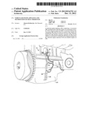
[0045] FIG. 1 depicts a vehicular engine appliance according to one embodiment of the present invention.
[0046] FIG. 2 depicts the elements of the vehicular engine appliance of FIG. 1.
[0047] FIG. 3 is a flowchart of the steps of the vehicular engine appliance of FIG. 1.
[0048] FIG. 4 depicts the dashboard receiving the results of the vehicular engine appliance of FIG. 1.
[0049] It should be understood that the drawings are not necessarily drawn to scale.
DETAILED DESCRIPTION OF PREFERRED EMBODIMENTS
[0050] The present invention will be understood from the following detailed description of preferred embodiments, which are meant to be descriptive and not limiting. For the sake of brevity, some well-known features, methods, systems, procedures, components, circuits, and so on, are not described in detail.
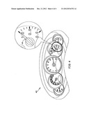
[0051] FIG. 1 depicts a vehicular engine appliance according to one embodiment of the present invention.
[0052] The term "viscometer" refers to any device from which viscosity may be measured.
[0053] A vehicular engine appliance 10 includes a pump 22 for circulating engine oil 14 from an engine oil reservoir 30 and thereto. The engine oil passes through a viscometer 18, to a thermometer 20 and back to reservoir 30.
[0054] Viscometer 18 provides a viscosity measurement signal to a processor 24, and thermometer 20 provides a temperature measurement signal to processor 24.
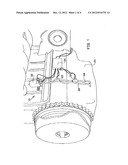
[0055] FIG. 2 depicts the elements of the vehicular engine appliance of FIG. 1.
[0056] An inlet pipe 28 sucks engine oil 14 and an outlet pipe 26 exhausts it through an orifice 16 reducing the flow back,
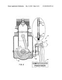
[0057] FIG. 3 is a flowchart of the steps of the vehicular engine appliance of FIG. 1.
[0058] Oil 14 is pumped from time to time, when the engine is at work, and as well, when not at work, thus the tests are performed at two temperature ranges, thus providing the characteristics classifying the oil. The temperature and the pressure are compared to data of engine oil. The result may be displayed to the dashboard 40 of the vehicle, or by another visual or vocal indication.
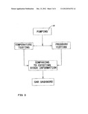
[0059] FIG. 4 depicts the dashboard receiving the results of the vehicular engine appliance FIG. 1.
[0060] Dashboard 40 may indicate the quality of the oil. The reference point of satisfactory quality may use the vehicle's requirements if relying on absolute data, and/or the measurements of new oil upon a change for relying on relative data.
[0061] The foregoing description and illustrations of the embodiments of the invention has been presented for the purposes of illustration. It is not intended to be exhaustive or to limit the invention to the above description in any form.
[0062] Any term that has been defined above and used in the claims, should to be interpreted according to this definition.
[0063] The reference numbers in the claims are not a part of the claims, but rather used for facilitating the reading thereof.
[0064] These, reference numbers should not be interpreted as limiting the claims in any form.
User Contributions:
Comment about this patent or add new information about this topic:
| People who visited this patent also read: | |
| Patent application number | Title |
|---|---|
| 20130209432 | PRODUCT AND PROCESS FOR LIQUEFACTION OF MUCUS OR SPUTUM |
| 20130209431 | ISOLATION AND CULTURE OF ERYTHROID PROGENITOR CELLS |
| 20130209430 | METHODS FOR REGULATION OF STEM CELLS |
| 20130209429 | Modulation of Tissue Fatty Acid Composition of a Host by Human Gut Bacteria |
| 20130209428 | METHOD OF INDUCING DIFFERENTIATION OF BONE MARROW STROMAL CELLS TO NEURAL PRECURSOR CELLS, NEURAL PRECURSOR CELLS, AND USES THEREOF |
Images included with this patent application:
 |  |
 |  |
 |
| New patent applications in this class: | |
| Date | Title |
|---|---|
| 2022-05-05 | Engine control device |
| 2019-05-16 | Machine learning for misfire detection in a dynamic firing level modulation controlled engine of a vehicle |
| 2019-05-16 | Method for diagnosing errors in an internal combustion engine |
| 2018-01-25 | Refueling controller |
| 2018-01-25 | Compressor override control |
| Top Inventors for class "Data processing: vehicles, navigation, and relative location" | |
| Rank | Inventor's name |
|---|---|
| 1 | Anthony H. Heap |
| 2 | Ajith Kuttannair Kumar |
| 3 | Christopher P. Ricci |
| 4 | Roderick A. Hyde |
| 5 | Lowell L. Wood, Jr. |