Patent application title: DENTAL HIGH VOLUME SUCTION TUBE WITH PROTECTIVE CAP
Inventors:
Faheem Pasha (Albuquerque, NM, US)
IPC8 Class: AA61C1710FI
USPC Class:
433 93
Class name: Apparatus having suction orifice and mouth prop, tongue guard or depressor, or cheek spreader
Publication date: 2012-10-18
Patent application number: 20120264080
Abstract:
This invention is a hollow, crown shaped cap along with the dental High
Volume Evacuation (HVE) tube into which the cap is specially designed to
fit. The crown shaped cap is detachable and attachable. The invention may
also be produced as one piece, with the cap permanently attached. The
crown shaped cap extends outward from the suction end, and is larger in
diameter than the HVE tube. This crown shaped cap for the HVE dental
suction tube consists of four tubular, question mark-shaped parts which
intersect to form four openings for suction. The cap is hollow and has a
short tubular end. The cap is attached to the suction end of the HVE tube
by snapping the tubular end of the cap into the suction end of the HVE
tube.
The crown shaped cap facilitates retraction of the tongue, cheeks or lips
within, and about, the oral cavity. It also enables a dentist to work on
teeth without the danger of causing tissue plug injury to the retracted
tongue, cheek or lips, while still allowing suction of larger particles.
The invention is designed to be disposable, for single use.Claims:
1-7. (canceled)
9-30. (canceled)
8. A dental suction tube for evacuating saliva and debris from a patient's mouth comprising, an elongated tubular member having a longitudinal central axis and including a distal end; and a cage structure at the tubular member distal end comprising four spaced apart vanes, each vane having a question-mark shape with a generally straight proximal section that extends from the tubular member distal end, a mid-section that curves outwardly away from the longitudinal central axis and a curved distal section that curves back to the longitudinal central axis, the straight section proximal end supported on the end of the tube and the distal ends of the curved distal sections of each vane attached to one another.
Description:
BACKGROUND OF THE INVENTION
[0001] The present invention is a cap and a tube for high volume dental suction. One end of the tube is designed to fit the cap.
[0002] High volume evacuation (HVE) suctions are used during dental procedures to remove saliva and particles, such as plaque, calculus, parts of existing fillings and decayed tooth material. Such HVE suction includes a suction tube having a distal (upper) suction end and a proximal (lower) discharge end. The discharge end of the suction tube is connected via a hose and hose valve to a vacuum source. The distal (upper) end of the suction tube is inserted into a patient's mouth.
[0003] The HVE suction tube is typically made of polyvinyl chloride or polyethylene. Such tips are hard and the edges rather sharp, which can irritate the tissue of a patient's mouth.
[0004] The suction draws material into the opening and down the tube. If the tip contacts the patient's mouth tissue, it can suck the tissue into the tip, obstructing the suction. This is uncomfortable and can cause damage to the patient's mouth and make it more difficult for the dental user. Such HVE suction tubes can require constant manual adjustments to maintain efficient suction while in use and cause unpleasant sensations, bruising and anxiety to patients
SUMMARY OF INVENTION
[0005] It is an objective of the present invention to provide a protective suction cap, and the specially designed HVE tube onto which it fits; the invention overcomes the aforementioned difficulties with existing HVE suction tube.
[0006] The HVE tube of the invention includes a tube having a suction end and a discharge end and which can be used with or without the protective cap attached.
[0007] The invention can also be produced as one piece, with the cap permanently attached to the HVE tube.
[0008] The cap provides a gap between suction end of the HVE tube and the oral tissue, to simultaneously allow tissue retraction and suction in the working area of an oral cavity, without causing trauma to fragile tissue.
[0009] The invention is made of polyethylene or other suitable plastic.
BRIEF DESCRIPTION OF THE DRAWINGS
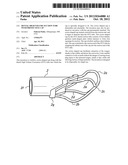
[0010] FIG. 1 is a right side view of the crown shaped cap.
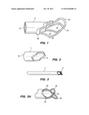
[0011] FIG. 2 is a right side view of the HVE suction tube of the present invention, specially designed to fit onto the crown shaped cap by pressing the cap into the suction end of the HVE tube.
[0012] FIG. 3 is a side view of the HVE suction tube with crown shaped tip permanently attached on the suction end as one piece.
[0013] FIG. 3A is a closer cutaway view of FIG. 2. It is a portion of the HVE tube with the crown shape cap permanently attached directly to the suction end of the HVE tube.
DETAILED DESCRIPTION OF THE INVENTION
[0014] The present invention includes the HVE suction tube 1 and a crown shaped cap 2. The HVE suction tube 1 has a suction end 1a, and a discharge end 1b, and is made of any suitable polymeric tubing, such as polyvinyl chloride or polyethylene. The HVE suction tube 1 is similar to a device well known in dentistry, and will be made to the standard industry length and diameter. The inside and outside diameters of the HVE suction tube 1 are also substantially the same as that used with currently existing HVE suction tubes.
[0015] Cap 2 is hollow and has a short tubular end section 2f and an open crown shaped cap, consisting of parts 2a, 2b, 2c, 2d, 2e on the other end. Cap 2 is attached to the suction end 1a, of suction tube 1 by pressure fit insertion of the tubular end section 2f, into the suction end 1a of tube 1.
[0016] Tubular, question mark-shaped parts 2a, 2b, 2d, 2e, of tube 2 intersect at 2c, dividing the cap into four openings and forming the crown shape of the cap. Each of the tubular, question mark-shaped parts 2a, 2b, 2d, 2e, of tube 2 extend from 2g of tube 2.
[0017] Tubular, question mark-shaped parts 2a, 2b, 2d, 2e can also be made to be permanently attached to, and extending from, the end la of tube 1. The open, crown-shaped cap formed by the tubular, question-mark shaped parts 2a, 2b, 2d, 2e is the unique feature of this invention; and it is this configuration on the suction end that functions to protect a dental patient's oral cavity from tissue plug injury.
[0018] Openings formed by the tubular, question mark-shaped parts 2a, 2b, 2d, 2e are large enough for higher uptake of aerosols as well as any larger particles generated during dental restorations.
[0019] HVE suction tube 1 is a straight shaped tube having a protective cap 2 at end 1a. End 1a functions as the suction end, and the protective cap 2 comes into contact with the patient's mouth tissue. Cap 2 is designed to minimize tissue plug injury while retracting the tissue, though still allowing suction. Cap 2 eliminates the danger of the tissue being grabbed as is frequent with existing dental suction tubes generally used in dental practices.
[0020] It will be obvious to those having skill in the art that many changes may be made to the details of the above-described invention without departing from the underlying principles thereof. The scope of the present invention should, therefore be determined only by the following claims.
User Contributions:
Comment about this patent or add new information about this topic:
Images included with this patent application:
 |  |
| Similar patent applications: | |
| Date | Title |
|---|---|
| 2013-10-03 | Expandable dental implant with improved mechanical retention |
| 2012-01-19 | Dental navigation techniques |
| 2012-09-13 | Dental probe with curette |
| 2012-09-20 | Dental probe with bristles |
| 2010-06-17 | Dental impression tray |
| New patent applications in this class: | |
| Date | Title |
|---|---|
| 2022-05-05 | Systems and methods to reduce spatter and aerosol during dental procedures |
| 2015-11-26 | Intraoral device and method of use |
| 2015-11-12 | Dental device with dual saliva extraction and dual retractor |
| 2015-04-02 | Patient controlled dental device and method |
| 2014-09-04 | Intraoral device adapter |
| New patent applications from these inventors: | |
| Date | Title |
|---|---|
| 2013-03-07 | Dental high volume suction tube with protective cap |
| 2009-08-27 | Business method and system for providing remuneration to consumers for viewing advertisements locally nationally and globally |
| Top Inventors for class "Dentistry" | |
| Rank | Inventor's name |
|---|---|
| 1 | Zachary B. Suttin |
| 2 | Eric Kuo |
| 3 | Bruce Berckmans, Iii |
| 4 | Marc Peuker |
| 5 | Sumita B. Mitra |