Patent application title: Exercise Apparatus
Inventors:
Steven Michael Bono (Commerce, MI, US)
IPC8 Class: AA63B2106FI
USPC Class:
482 93
Class name: Exercise devices user manipulated force resisting apparatus, component thereof, or accessory therefor utilizing weight resistance
Publication date: 2011-10-13
Patent application number: 20110251027
Abstract:
An exercise apparatus comprising a clamping assembly, one or more
adjustment plates, one or more pivot plates, and a weight bearing
assembly is provided. The clamping assembly comprises claw members, each
comprising a vertical web and horizontal flanges extending from the
vertical web. The horizontal flanges detachably clamp to a support
structure. The adjustment plates are rigidly attached to the vertical web
of one of the claw members and comprise apertures for enabling positional
adjustment of the weight bearing assembly. The pivot plates are rigidly
attached to the vertical web of another one of the claw members. The
weight bearing assembly comprises a leg member rigidly attached to a
support frame, and gripping handles. The leg member is pivotally
connected to the pivot plates and detachably connected to the adjustment
plates. The gripping handles that are rigidly supported by the support
frame are held by a user for performing exercises.Claims:
1. An exercise apparatus, comprising: a clamping assembly comprising claw
members, wherein each of said claw members comprises a vertical web and
two or more horizontal flanges, wherein said two or more horizontal
flanges extend from a first surface of said vertical web, and wherein
said two or more horizontal flanges of said claw members are detachably
clamped on opposing sides of a support structure for accommodating said
support structure; one or more adjustment plates rigidly attached to a
second surface of said vertical web of one of said claw members of said
clamping assembly, wherein said one or more adjustment plates extend
outwardly and perpendicularly from said second surface of said vertical
web of said one of said claw members; one or more pivot plates rigidly
attached to said second surface of said vertical web of another one of
said claw members of said clamping assembly, wherein said one or more
pivot plates extend outwardly and perpendicularly from said second
surface of said vertical web of said another one of said claw members;
and a weight bearing assembly comprising: a leg member having a first
end, a middle section, and a second end, wherein said first end of said
leg member is pivotally connected to said one or more pivot plates, said
middle section of said leg member is detachably connected to said one or
more adjustment plates, and said second end of said leg member is rigidly
attached to a support frame; and one or more gripping handles rigidly
supported by said support frame, wherein said one or more gripping
handles are held by a user for performing exercises.
2. The exercise apparatus of claim 1, wherein said one or more adjustment plates comprise apertures for enabling positional adjustment of said weight bearing assembly.
3. The exercise apparatus of claim 2, further comprising an adjustment fastener coaxially aligned with said apertures and inserted into said apertures of said one or more adjustment plates for enabling said positional adjustment of said weight bearing assembly.
4. The exercise apparatus of claim 3, wherein said leg member of said weight bearing assembly is positionally adjusted by inserting said adjustment fastener in selected said apertures of said one or more adjustment plates.
5. The exercise apparatus of claim 1, wherein said leg member is accommodated in a space defined between each of a pair of said pivot plates and a pair of said adjustment plates.
6. The exercise apparatus of claim 1, wherein said support frame of said weight bearing assembly comprises lateral arms extending outwardly from a base of said support frame, wherein said lateral arms comprise openings for inserting an elongated rod within a space defined by said lateral arms and said base of said support frame.
7. The exercise apparatus of claim 1, wherein said one or more gripping handles of said weight bearing assembly comprise a pair of gripping bars rigidly attached to ends of lateral arms of said support frame.
8. The exercise apparatus of claim 1, wherein said one or more gripping handles of said weight bearing assembly comprise an elongated rod rigidly attached within said support frame.
9. The exercise apparatus of claim 1, wherein said one or more gripping handles of said weight bearing assembly are coated with a gripping material for providing a grip to said user.
10. The exercise apparatus of claim 1, wherein said weight bearing assembly further comprises: a pulley rigidly attached to said leg member of said weight bearing assembly; and a cable having a first end and a second end, wherein said cable is rollably attached to and disposed within said pulley, wherein said first end of said cable bears one or more weights, and said second end of said cable is removably attached to a user.
11. A method for detachably attaching an exercise apparatus to a support structure and performing exercises by a user, comprising: providing said exercise apparatus comprising: a clamping assembly comprising claw members, wherein each of said claw members comprises a vertical web and two or more horizontal flanges, wherein said two or more horizontal flanges extend from a first surface of said vertical web; one or more adjustment plates rigidly attached to a second surface of said vertical web of one of said claw members of said clamping assembly, wherein said one or more adjustment plates extend outwardly and perpendicularly from said second surface of said vertical web of said one of said claw members, wherein said one or more adjustment plates comprise apertures for enabling positional adjustment of a weight bearing assembly; one or more pivot plates rigidly attached to said second surface of said vertical web of another one of said claw members of said clamping assembly, wherein said one or more pivot plates extend outwardly and perpendicularly from said second surface of said vertical web of said another one of said claw members; and said weight bearing assembly comprising: a leg member having a first end, a middle section, and a second end, wherein said first end of said leg member is pivotally connected to said one or more pivot plates, said middle section of said leg member is detachably connected to said one or more adjustment plates, and said second end of said leg member is rigidly attached to a support frame; and one or more gripping handles rigidly supported by said support frame; detachably clamping said two or more horizontal flanges of said claw members on opposing sides of said support structure for accommodating said support structure; positionally adjusting said leg member of said weight bearing assembly at one of a plurality of heights by rotating said leg member about a pivoting axis passing through an aperture of each of said pivot plates, and inserting an adjustment fastener in selected said apertures of said one or more adjustment plates; and gripping and pulling said one or more gripping handles against a force of gravity by said user for performing said exercises.
12. The method of claim 11, further comprising: rigidly attaching a pulley to said leg member of said weight bearing assembly; rollably attaching a cable to said pulley; removably attaching one or more weights to a first end of said cable; and removably attaching a second end of said cable to a user, wherein said one or more weights at said first end of said cable counterbalance a weight of said user at said second end of said cable.
13. A method for assembling an exercise apparatus, comprising: providing a clamping assembly comprising claw members, one or more adjustment plates, one or more pivot plates, and a weight bearing assembly, wherein each of said claw members comprises a vertical web and two or more horizontal flanges extending from a first surface of said vertical web, and wherein said weight bearing assembly comprises a leg member having a first end, a middle section and a second end, a support frame, and one or more gripping handles; rigidly attaching said one or more adjustment plates to a second surface of said vertical web of one of said claw members of said clamping assembly, wherein said one or more adjustment plates extend outwardly and perpendicularly from said second surface of said vertical web of said one of said claw members; rigidly attaching one or more pivot plates to said second surface of said vertical web of another one of said claw members of said clamping assembly, wherein said one or more pivot plates extend outwardly and perpendicularly from said second surface of said vertical web of said another one of said claw members; pivotally connecting said first end of said leg member of said weight bearing assembly in a space defined between said one or more pivot plates; detachably connecting said middle section of said leg member of said weight bearing assembly in a space defined between said one or more adjustment plates; rigidly attaching said second end of said leg member of said weight bearing assembly to said support frame; and rigidly attaching said one or more gripping handles to said support frame.
14. The method of claim 13, further comprising: rigidly attaching a pulley to said leg member of said weight bearing assembly; and rollably attaching a cable having a first end and a second end on said pulley, wherein said first end of said cable bears one or more weights, and said second end of said cable is removably attachable to a user.
15. The method of claim 13, wherein said one or more gripping handles of said weight bearing assembly comprise one or more of: a pair of gripping bars, wherein said gripping bars are rigidly attached to ends of lateral arms of said support frame; and an elongated rod, wherein said elongated rod is inserted into openings defined on said ends of said lateral arms of said support frame and disposed within a space defined by said support frame.
Description:
CROSS REFERENCE TO RELATED APPLICATIONS
[0001] This application claims the benefit of provisional patent application No. 61/323,453 titled "Exercise Apparatus", filed on Apr. 13, 2010 in the United States Patent and Trademark Office.
[0002] The specification of the above referenced application is incorporated herein by reference in its entirety.
BACKGROUND
[0003] A conventional exercise apparatus typically comprises a fixture that needs to be fixed in a specified location to ensure its proper usage. Typical exercise apparatuses housed in fitness centers, fitness clubs, and other gym recreation rooms, etc., are heavy, immobile, occupy large spaces, and are inconvenient to manage and use.
[0004] Moreover, the design of a conventional exercise apparatus limits the use of the exercise apparatus to persons in a certain height range. There is a need for an exercise apparatus that can be used with minimal effort and which by its inherent design ensures universal accessibility to different persons and different requirements such as height requirements, space usage requirements, and other physical requirements. Furthermore, there is a need for an exercise apparatus that can be easily installed and uninstalled in any convenient location as desired by a user to allow the user to perform different types of exercises.
[0005] Hence, there is a long felt but unresolved need for an exercise apparatus that is portable, easily installed and uninstalled in any desired location, and customizable for enabling a user of any height to perform different types of exercises.
SUMMARY OF THE INVENTION
[0006] This summary is provided to introduce a selection of concepts in a simplified form that are further described in the detailed description of the invention. This summary is not intended to identify key or essential inventive concepts of the claimed subject matter, nor is it intended for determining the scope of the claimed subject matter.
[0007] The exercise apparatus disclosed herein addresses the above stated need for a portable, easily installable, detachable, and customizable apparatus that enables a user of any height to perform exercises. The exercise apparatus disclosed herein comprises a clamping assembly, one or more adjustment plates, one or more pivot plates, and a weight bearing assembly. The clamping assembly comprises, for example, at least two claw members, namely a first claw member and a second claw member. Each of the claw members comprises a vertical web and two or more horizontal flanges. The horizontal flanges extend from a first surface of the vertical web. The horizontal flanges of the claw members are detachably clamped to opposing sides of a support structure, for example, an I-beam, for accommodating the support structure. The adjustment plates are rigidly attached to a second surface of the vertical web of the first claw member of the clamping assembly. The adjustment plates extend outwardly and perpendicularly from the second surface of the vertical web of the first claw member. The adjustment plates comprise apertures for enabling positional adjustment of the weight bearing assembly. The pivot plates are rigidly attached to the second surface of the vertical web of the second claw member of the clamping assembly. The pivot plates extend outwardly and perpendicularly from the second surface of the vertical web of the second claw member of the clamping assembly.
[0008] The weight bearing assembly comprises a leg member, a support frame, and one or more gripping handles. The leg member has a first end, a middle section, and a second end. The first end of the leg member is pivotally connected to the pivot plates in a space defined between the pivot plates. The middle section of the leg member is detachably connected to the adjustment plates in a space defined between the adjustment plates. The second end of the leg member is rigidly attached to a base of the support frame. The leg member is accommodated in the space defined between each of a pair of pivot plates and a pair of adjustment plates. The exercise apparatus further comprises an adjustment fastener coaxially aligned with the apertures of the adjustment plates and inserted into the apertures of the adjustment plates for enabling positional adjustment of the weight bearing assembly. The leg member is positionally adjusted by inserting the adjustment fastener in selected apertures of the adjustment plates.
[0009] The support frame rigidly supports the gripping handles of the weight bearing assembly. The support frame comprises lateral arms extending outwardly from the base of the support frame. The gripping handles are held by a user for performing pull up exercises. In an embodiment, the gripping handles comprise a pair of gripping bars. The gripping bars are rigidly attached to the ends of the lateral arms of the support frame. In another embodiment, the gripping handles further comprise an elongated rod rigidly attached within the support frame. The lateral arms of the support frame comprise openings for inserting the elongated rod within a space defined by the lateral arms and the base of the support frame. The user grips and pulls the gripping handles against a force of gravity for performing the exercises. In an embodiment, the gripping handles are coated with a gripping material for providing an improved grip to the user.
[0010] In an embodiment, the weight bearing assembly further comprises a pulley, a cable having a first end and a second end, and one or more weights. The pulley is rigidly attached to a bottom surface of the leg member of the weight bearing assembly. The cable is rollably attached to and disposed within the pulley. The first end of the cable bears the weights. The second end of the cable is removably attached to the user. The weights at the first end of the cable counterbalance the user's weight at the second end of the cable, while the user performs exercises.
BRIEF DESCRIPTION OF THE DRAWINGS
[0011] The foregoing summary, as well as the following detailed description of the invention, is better understood when read in conjunction with the appended drawings. For the purpose of illustrating the invention, exemplary constructions of the invention are shown in the drawings. However, the invention is not limited to the specific components and methods disclosed herein.
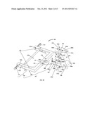
[0012] FIGS. 1A-1B exemplarily illustrate perspective views of an exercise apparatus.
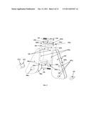
[0013] FIG. 2 exemplarily illustrates a top orthogonal view of the exercise apparatus.
[0014] FIG. 3 exemplarily illustrates a side orthogonal view of the exercise apparatus.
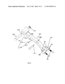
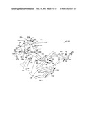
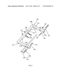
[0015] FIG. 4 exemplarily illustrates an exploded view of the exercise apparatus.
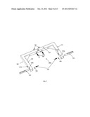
[0016] FIG. 5 exemplarily illustrates an exploded view of a clamping assembly of the exercise apparatus, showing two adjustment plates and two pivot plates connected to the claw members of the clamping assembly.
[0017] FIG. 6 exemplarily illustrates an exploded view of a leg member of a weight bearing assembly of the exercise apparatus.
[0018] FIG. 7 exemplarily illustrates an exploded view of a support frame of the weight bearing assembly of the exercise apparatus, showing gripping bars extending outwardly from the ends of lateral arms of the support frame.
[0019] FIG. 8 exemplarily illustrates an exploded view of a support frame of the weight bearing assembly of the exercise apparatus, showing the gripping bars and an elongated rod used for performing exercises by a user.
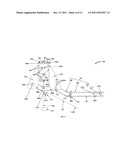
[0020] FIG. 9 exemplarily illustrates the exercise apparatus detachably attached to a support structure.
[0021] FIG. 10 exemplarily illustrates positional adjustment of the leg member of the weight bearing assembly of the exercise apparatus.
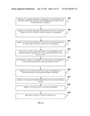
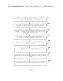
[0022] FIG. 11 illustrates a method for detachably attaching an exercise apparatus to a support structure and performing exercises by a user.
[0023] FIG. 12 illustrates a method for assembling an exercise apparatus.
DETAILED DESCRIPTION OF THE INVENTION
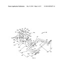
[0024] FIGS. 1A-1B exemplarily illustrate perspective views of an exercise apparatus 100. The exercise apparatus 100 disclosed herein comprises a clamping assembly 101, one or more adjustment plates 105, one or more pivot plates 106, and a weight bearing assembly 107. The clamping assembly 101 comprises claw members 102a and 102b. As exemplarily illustrated in FIGS. 1A-1B, FIGS. 2-5, and FIGS. 9-10, the clamping assembly 101 comprises at least two claw members 102a and 102b, namely a first claw member 102a and a second claw member 102b. Each of the claw members 102a and 102b comprises a vertical web 103 and two or more horizontal flanges 104. The horizontal flanges 104 extend from a first surface 103a of the vertical web 103. The horizontal flanges 104 of the claw members 102a and 102b are, for example, welded on the first surface 103a of the vertical web 103. The horizontal flanges 104 of the claw members 102a and 102b are detachably clamped on opposing sides 128a and 128b of a support structure 128, for example, an I-beam or other beam structures of roofs, basements, doors, etc., as exemplarily illustrated in FIG. 9. In an embodiment, the horizontal flanges 104 of the claw members 102a and 102b detachably attach to the support structure 128, for example, by bolts 118, anchor nut screws, etc. The clamped claw members 102a and 102b of the clamping assembly 101 accommodate the support structure 128. The claw members 102a and 102b are made of high strength materials, for example, alloys of steel, alloys of aluminum, etc.
[0025] As exemplarily illustrated in FIGS. 1A-1B, FIGS. 2-5, and FIGS. 9-10, the exercise apparatus 100 disclosed herein comprises at least two adjustment plates 105. The adjustment plates 105 of the exercise apparatus 100 disclosed herein are rigidly attached to a second surface 103b of the vertical web 103 of the first claw member 102a of the clamping assembly 101, for example, by a weld, a lock and key joint, etc. The adjustment plates 105 extend outwardly and perpendicularly from the second surface 103b of the vertical web 103 of the first claw member 102a. The adjustment plates 105 are made of high strength materials, for example, alloys of steel, alloys of aluminum, wood, etc. The adjustment plates 105 comprise apertures 105a for enabling positional adjustment of the weight bearing assembly 107.
[0026] As exemplarily illustrated in FIG. 1B, FIG. 2, and FIG. 5, the exercise apparatus 100 disclosed herein comprises at least two pivot plates 106. The pivot plates 106 are rigidly attached to the second surface 103b of the vertical web 103 of the second claw member 102b of the clamping assembly 101, for example, by a weld, a lock and key joint, etc. The pivot plates 106 extend outwardly and perpendicularly from the second surface 103b of the vertical web 103 of the second claw member 102b. The pivot plates 106 are made of high strength materials, for example, alloys of steel, alloys of aluminum, wood, etc. Each of the pivot plates 106 comprises a pivot aperture 106a. A pivoting axis 106b centrally passes through the pivot aperture 106a of each of the pivot plates 106. The weight bearing assembly 107 rotates about the pivoting axis 106b to adjust the position, for example, the vertical height, of the weight bearing assembly 107.
[0027] The weight bearing assembly 107 comprises a leg member 108, a support frame 109, and one or more gripping handles 110. The leg member 108 is rigidly attached to the support frame 109, for example, by a weld, bolts 119, rivets, etc. The leg member 108 has a first end 108a, a middle section 108b, and a second end 108c. The first end 108a of the leg member 108 is pivotally connected to the pivot plates 106 in a space 106c defined between the pivot plates 106. The middle section 108b of the leg member 108 is detachably connected to the adjustment plates 105 in a space 105b defined between the adjustment plates 105. The second end 108c of the leg member 108 is rigidly attached to a base 111 of the support frame 109.
[0028] As exemplarily illustrated in FIGS. 1A-1B, FIGS. 2-4, and FIGS. 9-10, the leg member 108 is supported and disposed between two pivot plates 106 and two adjustment plates 105. The leg member 108 is pivotally connected to the pivot plates 106 via the pivot aperture 106a of the pivot plates 106, for example, by a pin, a bolt, a split pin, a pivot sleeve 127a and a pivot sleeve cap screw 127c, etc. The leg member 108 is also detachably connected to the adjustment plates 105 via a set of opposing apertures 105a of the adjustment plates 105 by an adjustment fastener 115, for example, a pull out pin. The leg member 108 is selectively connected to the opposing apertures 105a of the adjustment plates 105 to adjust the position of the weight bearing assembly 107.
[0029] The exercise apparatus 100 disclosed herein further comprises the adjustment fastener 115 coaxially aligned with and inserted into the apertures 105a of the adjustment plates 105 for enabling positional adjustment of the weight bearing assembly 107. The leg member 108 is positionally adjusted by inserting the adjustment fastener 115 in selected apertures 105a of the adjustment plates 105 as exemplarily illustrated in FIGS. 1A-1B, FIGS. 3-4, and FIGS. 9-10. The leg member 108 is accommodated in the space 106c and 105b defined between a pair of pivot plates 106 and a pair of adjustment plates 105 respectively. The weight bearing assembly 107 is made of high strength materials, for example, alloys of steel, alloys of aluminum, carbon fiber composites, etc. The weight bearing assembly 107 rotates about the pivoting axis 106b for adjusting the position of the weight bearing assembly 107.
[0030] The support frame 109 of the weight bearing assembly 107 rigidly supports the gripping handles 110 of the weight bearing assembly 107. The support frame 109 comprises lateral arms 112 extending outwardly from a base 111 of the support frame 109. The gripping handles 110 of the weight bearing assembly 107 are held by a user for performing exercises, for example, pull up exercises. In an embodiment as exemplarily illustrated in FIGS. 1A-1B, FIG. 2, FIG. 4, and FIGS. 7-9, the gripping handles 110 comprise a pair of gripping bars 113. The gripping bars 113 are rigidly attached to the ends 112a of the lateral arms 112 of the support frame 109, for example, by a weld, bolts 125, etc. The gripping bars 113 extend outwardly from the lateral arms 112 of the support frame 109. In an embodiment, the gripping bars 113 extend inwardly from the support frame 109. In another embodiment as exemplarily illustrated in FIGS. 1A-1B, FIG. 2, FIG. 4, and FIGS. 8-9, the gripping handles 110 comprise an elongated rod 114. The elongated rod 114 is rigidly attached within the support frame 109, for example, by a fastening screw 126, etc. The lateral arms 112 of the support frame 109 comprise openings 112b and 112c for inserting the elongated rod 114 within a space 109a defined by the lateral arms 112 and the base 111 of the support frame 109. The user can hold the gripping bars 113 and/or the elongated rod 114 for performing pull up exercises. In an embodiment, the gripping handles 110 are coated with a gripping material, for example, a form of plastic, synthetic rubber, etc., for providing an improved grip to the user. In another embodiment, the gripping handles 110 are manufactured with a gripping surface such as a cross hatching, a knurled surface, etc., for providing an improved grip to the user. In an embodiment, a pulley 117 is rigidly attached to the leg member 108 of the weight bearing assembly 107 as disclosed in the detailed description of FIG. 3.
[0031] FIG. 2 exemplarily illustrates a top orthogonal view of the exercise apparatus 100. The claw members 102a and 102b of the clamping assembly 101 are clamped around a support structure 128 and connected using fasteners, for example, bolts 118 to rigidly accommodate the support structure 128 as disclosed in the detailed description of FIG. 5. The leg member 108 of the weight bearing assembly 107 is supported and disposed between two pivot plates 106 and two adjustment plates 105. The leg member 108 of the weight bearing assembly 107 is adjusted using the adjustment plates 105. The exercise apparatus 100 has a clamshell design and bolts to the support structure 128.
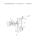
[0032] FIG. 3 exemplarily illustrates a side orthogonal view of the exercise apparatus 100. FIG. 3 illustrates the claw members 102a and 102b of the clamping assembly 101 in a clamped position. The clamping assembly 101, the adjustable plates 105, the pivot plates 106, and the weight bearing assembly 107 are disclosed in the detailed description of FIGS. 1A-1B. In an embodiment, the weight bearing assembly 107 further comprises a pulley 117 and a cable 122. The pulley 117 is rigidly attached to, for example, a bottom surface 108d of the leg member 108 of the weight bearing assembly 107. The cable 122, for example, a cord, a rope, a thick metal wire, etc., has a first end 122a and a second end 122b. The cable 122 is rollably attached to and disposed within the pulley 117. The first end 122a of the cable 122 bears one or more weights 123. The weights 123 are, for example, calibrated weights, sand bags, etc. The second end 122b of the cable 122 is removably attached, for example, to a belt (not shown) of a user performing an exercise. The weights 123 at the first end 122a of the cable 122 counterbalance the user's weight at the second end 122b of the cable 122, thereby reducing work done by the user to perform pull up exercises. In an embodiment, a belt (not shown) is detachably attached to the second end 122b of the cable 122. The belt is worn around the user's waist. The number of weights 123 to be added depends on the exercise requirements of the user. The user therefore performs exercises using the exercise apparatus 100.
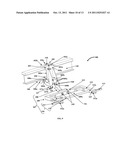
[0033] FIG. 4 exemplarily illustrates an exploded view of the exercise apparatus 100. The exploded view in FIG. 4 illustrates the fasteners 118 used for connecting the clamping assembly 101 around a support structure 128, and the fasteners 127a, 127c, and 115 for connecting the weight bearing assembly 107 to the pivot plates 106 and the adjustment plates 105 via the leg member 108. The leg member 108 is pivotally connected to the pivot plates 106 via the pivot sleeve 127a and the pivot sleeve cap screw 127c through the edge 127b and detachably connected to the adjustment plates 105 via the adjustment fastener 115. The exploded view in FIG. 4 also illustrates the fasteners 119 and 121 used for connecting the leg member 108 to the support frame 109, and the fasteners 125 and 126 for connecting the gripping handles 110 to the support frame 109. The different fasteners 118 used in the exercise apparatus 100 are disclosed in the detailed description of FIGS. 5-8.
[0034] FIG. 5 exemplarily illustrates an exploded view of a clamping assembly 101 of the exercise apparatus 100, showing two adjustment plates 105 and two pivot plates 106 connected to the claw members 102a and 102b of the clamping assembly 101. The adjustment plates 105 are rigidly attached to the second surface 103b of the first claw member 102a. Each of the adjustment plates 105 comprises apertures 105a for enabling positional adjustment of the weight bearing assembly 107 by inserting an adjustment fastener 115, for example, a pin, bolt, etc., into selective opposing apertures 105a of the adjustment plates 105. The pivot plates 106 are rigidly attached to the second surface 103b of the second claw member 102b. Each of the pivot plates 106 comprises a pivot aperture 106a. The leg member 108 of the weight bearing assembly 107 is pivotally connected to the pivot plates 106 using, for example, a pivot sleeve 127a and a pivot sleeve cap screw 127c. The pivot sleeve 127a is inserted into the pivot aperture 106a of a pivot plate 106, through the leg member 108, and into the pivot aperture 106a of the other pivot plate 106. The pivot sleeve cap screw 127c is then inserted at the edge 127b of the pivot sleeve 127a to fasten the leg member 108 to the pivot plates 106 in a pivotal connection. The claw members 102a and 102b of the clamping assembly 101 are clamped and fastened at the top surface 101a and the bottom surface 101b of the claw members 102a and 102b around a support structure 128, for example, using bolts 118. The bolts 118 fit axially into slots 102c and 102d provided on the top surface 101a and the bottom surface 101b of the claw members 102a and 102b.
[0035] FIG. 6 exemplarily illustrates an exploded view of a leg member 108 of a weight bearing assembly 107 of the exercise apparatus 100. The leg member 108 is a load bearing member that bears the weight of the user while the user performs exercises. The leg member 108 is pivotally connected to the pivot plates 106, for example, using a pivot sleeve 127a and a pivot sleeve cap screw 127c as disclosed in the detailed description of FIG. 5. The adjustment fastener 115 is used to positionally adjust the leg member 108 between the adjustment plates 105. In an embodiment, a pulley 117 is rigidly attached to the bottom surface 108d of the leg member 108. Pulley hooks 117a are rigidly attached to the bottom surface 108d of the leg member 108 for accommodating a pulley wheel 117b. The pulley 117 comprises the pulley wheel 117b and a pulley pin 117c. The pulley wheel 117b is accommodated between two opposing pulley hooks 117a extending from the bottom surface 108d of the leg member 108 and rotatably fastened between the two opposing pulley hooks 117a via the pulley pin 117c. The leg member 108 is rigidly attached to the base 111 of the support frame 109 via a base plate 116 using fasteners, for example, lock nuts 121 and bolts 119 through washers 120.
[0036] FIG. 7 exemplarily illustrates an exploded view of a support frame 109 of the weight bearing assembly 107 of the exercise apparatus 100, showing gripping bars 113 extending outwardly from the ends 112a of the lateral arms 112 of the support frame 109. The support frame 109 comprises lateral arms 112 extending outwardly from a base 111 of the support frame 109. The base 111 of the support frame 109 is rigidly attached to the leg member 108 via a base plate 116 using fasteners, for example, lock nuts 121 and bolts 119 through washers 120. The gripping bars 113 are rigidly attached to the ends 112a of the lateral arms 112, for example, using bolts 125 and washers 124. A user grips and pulls the gripping bars 113 for performing pull exercises.
[0037] FIG. 8 exemplarily illustrates an exploded view of a support frame 109 of the weight bearing assembly 107, showing the gripping bars 113 and an elongated rod 114 used for performing exercises by a user. In an embodiment, the ends 112a of the lateral arms 112 of the support frame 109 comprise cylindrical openings 112b and 112c for inserting the elongated rod 114 in the support frame 109. The elongated rod 114 is a solid cylindrical structure made of, for example, steel, etc. The elongated rod 114 is inserted through a cylindrical opening 112b on one of the lateral arms 112 of the support frame 109 to the other cylindrical opening 112c on the other lateral arm 112 of the support frame 109. The elongated rod 114 is then fastened at the other cylindrical opening 112c, for example, using a fastening screw 126. The user grips and pulls the elongated rod 114 for performing pull exercises.
[0038] FIG. 9 exemplarily illustrates the exercise apparatus 100 detachably attached to a support structure 128, for example, an I-beam or other beam structures of roofs, basements, doors, etc. The horizontal flanges 104 of the claw members 102a and 102b of the clamping assembly 101 clamp the support structure 128 and are fastened around the support structure 128 using, for example, bolts 118. The bolts 118 fit axially into slots 102c and 102d provided on the top surface 101a and the bottom surface 101b of the claw members 102a and 102b.
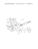
[0039] FIG. 10 exemplarily illustrates positional adjustment of the leg member 108 of the weight bearing assembly 107 of the exercise apparatus 100. In the exercise apparatus 100 disclosed herein, the first end 108a of the leg member 108 is pivotally connected about the pivot apertures 106a of the pivot plates 106 in the space 106c defined between the pivot plates 106. The direction of rotation of the leg member 108 is exemplarily illustrated in FIG. 10. The leg member 108 of the weight bearing assembly 107 rotates about the pivoting axis 106b to adjust the position, for example, the vertical height, of the weight bearing assembly 107. A user can increase the vertical height of the weight bearing assembly 107 by pulling out the adjustment fastener 115 from opposing apertures 105a corresponding to a first position, rotating the leg member 108 from the first position to a desired position about the pivoting axis 106b, and then re-inserting the adjustment fastener 115 into selected opposing apertures 105a corresponding to the desired position.
[0040] FIG. 11 illustrates a method for detachably attaching an exercise apparatus 100 to a support structure 128 and performing exercises by a user. The exercise apparatus 100 comprising a clamping assembly 101, one or more adjustment plates 105, one or more pivot plates 106, and a weight bearing assembly 107, as disclosed in the detailed description of FIGS. 1A-1B and FIGS. 2-10, is provided 1101. The horizontal flanges 104 of the claw members 102a and 102b of the clamping assembly 101 are detachably clamped 1102 around opposing sides 128a and 128b of the support structure 128 for accommodating the support structure 128 as exemplarily illustrated in FIG. 9. The leg member 108 of the weight bearing assembly 107 is positionally adjusted 1103 at one of different heights by rotating the leg member 108 about a pivoting axis 106b passing through a pivot aperture 106a of each of the pivot plates 106, and inserting an adjustment fastener 115 in selected apertures 105a of the adjustment plates 105 as exemplarily illustrated in FIG. 10. The gripping handles 110 are gripped and pulled 1104 against a force of gravity by the user for performing exercises, for example, pull up exercises. In an embodiment, a pulley 117 is rigidly attached 1105 to the leg member 108 of the weight bearing assembly 107 and a cable 122 is rollably attached 1106 to the pulley 117. The user removably attaches 1107 one or more weights 123 to the first end 122a of the cable 122. The user then removably attaches 1108 the second end 122b of the cable 122 to a belt positioned around the user's waist. The weights 123, for example, calibrated weights, sand bags, etc., at the first end 122a of the cable 122 counterbalance the user's weight at the second end 122b of the cable 122.
[0041] FIG. 12 illustrates a method for assembling an exercise apparatus 100. A clamping assembly 101 comprising claw members 102a and 102b, one or more adjustment plates 105, one or more pivot plates 106, and a weight bearing assembly 107 is provided 1201. The adjustment plates 105 are rigidly attached 1202 to a second surface 103b of the vertical web 103 of a first claw member 102a of the clamping assembly 101. The adjustment plates 105 extend outwardly and perpendicularly from the second surface 103b of the vertical web 103 of the first claw member 102a. The pivot plates 106 are rigidly attached 1203 to the second surface 103b of the vertical web 103 of the second claw member 102b of the clamping assembly 101. The pivot plates 106 extend outwardly and perpendicularly from the second surface 103b of the vertical web 103 of the second claw member 102b. The first end 108a of the leg member 108 of the weight bearing assembly 107 is pivotally connected 1204 in the space 106c defined between the pivot plates 106, for example, using a pivot sleeve 127a and a pivot sleeve cap screw 127c. The middle section 108b of the leg member 108 of the weight bearing assembly 107 is detachably connected 1205 in the space 105b defined between the adjustment plates 105, for example, by the adjustment fastener 115. The second end 108c of the leg member 108 of the weight bearing assembly 107 is rigidly attached 1206 to the support frame 109. The gripping handles 110 are rigidly attached 1207 to the support frame 109. For example, the gripping bars 113 are rigidly attached to the ends 112a of the lateral arms 112 of the support frame 109. An elongated rod 114 can also be inserted into openings 112b and 112c defined on the ends 112a of the lateral arms 112 of the support frame 109 and disposed within the space 109a defined by the support frame 109. A pulley 117 is rigidly attached 1208 to the leg member 108 of the weight bearing assembly 107. A cable 122, for example, a cord, a rope, a thick metal wire, etc., is rollably attached 1209 to the pulley 117, where the first end 122a of the cable 122 bears one or more weights 123, and the second end 122b of the cable 122 is removably attachable to a user.
[0042] Consider an example where a user performs exercises using the exercise apparatus 100 disclosed herein. The exercise apparatus 100 is detachably attached, for example, by bolts 118, countersunk bolts, etc., to a support structure 128, for example, an I-beam of a ceiling. The user adjusts the position of the weight bearing assembly 107 to one of different heights by rotating the weight bearing assembly 107 about the pivoting axis 106b and selectively connecting the leg member 108 of the weight bearing assembly 107 to opposing apertures 105a of the adjustment plates 105 using the adjustment fastener 115. The position of the weight bearing assembly 107 is selected based on preferences of the user. The user attaches the first end 122a of the cable 122 disposed within the pulley 117 to one or more weights 123. The user then attaches the second end 122b of the cable 122 around the user's waist. The weights 123, for example, calibrated weights, sand bags, etc., at the first end 122a of the cable 122 counterbalance the user's weight at the second end 122b of the cable 122, thereby reducing work done by the user to perform pull up exercises. The user now holds the gripping handles 110 and pulls upwards against the force of gravity to perform pull up exercises.
[0043] The exercise apparatus 100 disclosed herein allows the user to perform the pull up exercises repeatedly in an uninhibited motion, where the user has adequate clearances in multiple directions. The exercise apparatus 100 disclosed herein also enables a beginner to complete a full range of motion with the assistance of the weights 123 that counterbalance the user's weight via the pulley 117 until the beginner is strong enough to perform the pull up exercises without assistance. Furthermore, seasoned athletes can use the weights 123 that counterbalance their weight via the pulley 117 to perform negative repetitions, when the athletes have pushed themselves past a point of exhaustion.
[0044] The foregoing examples have been provided merely for the purpose of explanation and are in no way to be construed as limiting of the present invention disclosed herein. While the invention has been described with reference to various embodiments, it is understood that the words, which have been used herein, are words of description and illustration, rather than words of limitation. Further, although the invention has been described herein with reference to particular means, materials and embodiments, the invention is not intended to be limited to the particulars disclosed herein; rather, the invention extends to all functionally equivalent structures, methods and uses, such as are within the scope of the appended claims. Those skilled in the art, having the benefit of the teachings of this specification, may effect numerous modifications thereto and changes may be made without departing from the scope and spirit of the invention in its aspects.
User Contributions:
Comment about this patent or add new information about this topic:
Images included with this patent application:
 |  |
 |  |
 |  |
 |  |
 |  |
 |  |
 |
| Similar patent applications: | |
| Date | Title |
|---|---|
| 2009-02-12 | Therapeutic or exercise apparatus |
| 2009-02-19 | Bicycling exercise apparatus |
| 2009-02-26 | Exercise apparatus |
| 2009-03-05 | Stationary exercise apparatus |
| 2009-03-05 | Adjustable exercise apparatus |
| New patent applications in this class: | |
| Date | Title |
|---|---|
| 2022-05-05 | Modified weight training equipment |
| 2017-08-17 | Method and apparatus for exercising abdominal muscles |
| 2017-08-17 | Postural dynamics exercise system |
| 2016-12-29 | Multi-purpose exercise device |
| 2016-07-07 | Muscle training method and muscle training system |
| New patent applications from these inventors: | |
| Date | Title |
|---|---|
| 2011-10-13 | Exercise apparatus |
| Top Inventors for class "Exercise devices" | |
| Rank | Inventor's name |
|---|---|
| 1 | William T. Dalebout |
| 2 | Scott R. Watterson |
| 3 | Raymond Giannelli |
| 4 | Leao Wang |
| 5 | Bruce Hockridge |