Patent application title: EXTERNAL SOLE LINER AND METHOD OF MANUFACTURING AND USING THE SAME
Inventors:
Steven M. Trevino (Mesa, AZ, US)
IPC8 Class: AA43B1312FI
USPC Class:
36 30 R
Class name: Boots, shoes, and leggings soles laminated
Publication date: 2010-02-25
Patent application number: 20100043255
Inventors list |
Agents list |
Assignees list |
List by place |
Classification tree browser |
Top 100 Inventors |
Top 100 Agents |
Top 100 Assignees |
Usenet FAQ Index |
Documents |
Other FAQs |
Patent application title: EXTERNAL SOLE LINER AND METHOD OF MANUFACTURING AND USING THE SAME
Inventors:
Steven M. Trevino
Agents:
SCHMEISER OLSEN & WATTS
Assignees:
Origin: MESA, AZ US
IPC8 Class: AA43B1312FI
USPC Class:
36 30 R
Patent application number: 20100043255
Abstract:
Footwear includes an external sole liner having a tread surface and an
exposed adhesive layer. A cleat is bonded to the tread surface, and
tapers in response to being bonded to the tread surface. The external
sole liner can include multiple layers of liners which are separable from
each other.Claims:
1. Footwear, comprising:an external sole liner having a tread surface;an
exposed adhesive layer carried by the external sole liner opposed to the
tread surface; anda cleat bonded to the tread surface.
2. The footwear of claim 1, wherein the external sole liner includes multiple layers of liners which are separable from each other.
3. The footwear of claim 1, wherein the external sole liner includes a corrugation, and the cleat is bonded to the corrugation.
4. The footwear of claim 3, wherein the cleat tapers in response to being bonded to the corrugation.
5. The footwear of claim 3, wherein the corrugation includes a channel, and the cleat tapers in response to extending through the channel.
6. The footwear of claim 1, wherein the cleat includes first and second material layers, wherein a portion of the second material layer extends over a portion of the first material layer.
7. Footwear, comprising:an external sole liner having a tread surface, the external sole liner including multiple layers of liners; anda cleat bonded to the tread surface.
8. The footwear of claim 7, wherein the liners are separable from each other.
9. The footwear of claim 8, further including an adhesive layer carried by each liner.
10. The footwear of claim 7, wherein the cleat is longitudinal with a length that extends along the tread surface.
11. The footwear of claim 10, wherein the external sole liner includes a corrugation having a channel, and the cleat tapers in response to extending over the channel.
12. The footwear of claim 7, wherein the external sole liner includes a corrugation having a channel, and the cleat tapers in response to extending over the channel.
13. The footwear of claim 12, wherein the cleat includes first and second material layers positioned proximate to each other, the first and second material layers tapering in response to extending over the channel.
14. Footwear, comprising:an external sole liner having a plurality of channels;an adhesive layer carried by the external sole liner opposed to the channels; anda cleat carried by the external sole liner, wherein the cleat is bonded to adjacent channels.
15. The footwear of claim 14, wherein the external sole liner includes a plurality of liners which are separable from each other.
16. The footwear of claim 14, wherein the cleat includes a first material layer with a portion which extends inside a channel and a portion which extends outside the channel.
17. The footwear of claim 16, wherein the first material layer is longitudinal in shape and extends along the external sole liner.
18. The footwear of claim 16, wherein the cleat includes a second material layer positioned proximate to the first material layer.
19. The footwear of claim 18, wherein the first material layer surrounds the second material layer.
20. The footwear of claim 18, wherein the second material layer is tapered in response to extending over the first material layer.
Description:
CROSS-REFERENCE TO RELATED APPLICATION
[0001]The present application claims priority to U.S. provisional application Ser. No. 61/090,806, filed on Aug. 21, 2008, the contents of which are incorporated herein by reference.
BACKGROUND OF THE INVENTION
[0002]1. Field of the Invention
[0003]This invention relates generally to footwear which covers a foot sole.
[0004]2. Description of the Related Art
[0005]There are many different types of footwear, such as boots, slippers, sandals and shoes. These types of footwear generally include an upper coupled with an outsole so that a volume is defined for receiving a person's foot. A sole liner is often positioned between the outsole and upper to make the footwear more comfortable. More information regarding uppers, sole liners and outsoles can be found in U.S. Pat. Nos. 6,119,370, 7,421,808 and 7,437,838, the contents of all of which are incorporated herein by reference. In general, the upper includes a vamp which covers an upper portion of the person's foot, and the sole liner covers a lower portion of the person's foot. The outsole covers the sole liner so that the sole liner is internal to the footwear. In this way, the sole liner is an internal sole liner. The upper portion of the person's foot can include the side, top and ankle portions the foot, and the lower portion of the person's foot includes the sole.
[0006]Other types of footwear include the sole liner, but not the upper and/or outsole, so that a volume is not defined for receiving the person's foot. In these types of footwear, the sole liner is external to the footwear because the footwear does not include an outsole to cover the sole liner. In this way, the sole liner is an external sole liner. More information regarding footwear which includes an external sole liner can be found in U.S. Pat. Nos. 4,651,354, 6,640,465 and D545,532, as well as U.S. Patent Application Nos. 20050011084 and 20060207123, the contents of all of which are incorporated herein by reference. These types of external sole liners often have smooth surfaces which face away from the foot sole so that the external sole liner provides little traction. It is desirable, however, to provide an external sole liner which provides more traction.
BRIEF SUMMARY OF THE INVENTION
[0007]The present invention provides footwear which includes an external sole liner having a tread surface and an exposed adhesive layer carried by the external sole liner opposed to the tread surface. In accordance with the invention, a cleat is bonded to the tread surface.
[0008]In some embodiments, the external sole liner includes multiple layers of liners which are separable from each other. In some embodiments, the external sole liner includes a corrugation, and the cleat is bonded to the corrugation. In these embodiments, the cleat tapers in response to being bonded to the corrugation. The corrugation can include a channel, and the cleat tapers in response to extending through the channel. In some embodiments, the cleat includes first and second material layers, wherein a portion of the second material layer extends over a portion of the first material layer.
[0009]The present invention provides footwear which includes an external sole liner having a tread surface, wherein the external sole liner includes multiple layers of liners. In accordance with the invention, a cleat is bonded to the tread surface. The liners are generally separable from each other.
[0010]In some embodiments, the footwear includes an adhesive layer carried by each liner. In some embodiments, the cleat is longitudinal in shape with a length that extends along the tread surface. In some embodiments, the external sole liner includes a corrugation having a channel, and the cleat tapers in response to extending over the channel. In some embodiments, the cleat includes first and second material layers positioned proximate to each other, the first and second material layers tapering in response to extending over the channel.
[0011]The present invention provides footwear which includes an external sole liner having a plurality of channels and an adhesive layer carried by the external sole liner opposed to the channels. In accordance with the invention, a cleat is carried by the external sole liner, wherein the cleat is bonded to adjacent channels.
[0012]In some embodiments, the external sole liner includes a plurality of liners which are separable from each other. In some embodiments, the cleat includes a first material layer with a portion which extends inside a channel and a portion which extends outside the channel. In some embodiments, the first material layer is longitudinal in shape and extends along the external sole liner. In some embodiments, the cleat includes a second material layer positioned proximate to the first material layer. In some embodiments, the first material layer surrounds the second material layer. In some embodiments, the second material layer is tapered in response to extending over the first material layer.
[0013]These and other features, aspects, and advantages of the present invention will become better understood with reference to the following drawings and description.
BRIEF DESCRIPTION OF THE DRAWINGS
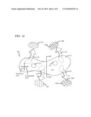
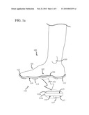
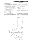
[0014]FIG. 1a is a side view of footwear, in accordance with the invention, being worn on a foot.
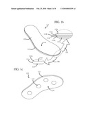
[0015]FIGS. 1b and 1c are top and bottom perspective views of the footwear of FIG. 1a.
[0016]FIG. 1d is a bottom view of the footwear of FIG. 1a.
[0017]FIG. 2a is a top view of a cleat having a longitudinal shape, wherein the cleat can be used with the footwear of FIG. 1a.
[0018]FIG. 2b is a top view of a cleat having a closed rectangular shape, wherein the cleat can be used with the footwear of FIG. 1a.
[0019]FIG. 2c is a top view of a cleat having a closed circular shape, wherein the cleat can be used with the footwear of FIG. 1a.
[0020]FIG. 2d is a top view of a cleat having a closed triangular shape, wherein the cleat can be used with the footwear of FIG. 1a.
[0021]FIG. 2e is a top view of a cleat having a closed diamond shape, wherein the cleat can be used with the footwear of FIG. 1a.
[0022]FIGS. 3a, 3b and 3c are side views, taken along a cut-line 3-3 of FIG. 1d, of different embodiments of a corrugation.
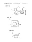
[0023]FIGS. 4a, 4b, 4c and 4d are side views of a cleat bonded to the corrugation of FIG. 3a, in accordance with the invention.
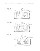
[0024]FIG. 5a is a top view of a cleat having multiple material layers, in accordance with the invention, bonded to a tread surface of the footwear of FIG. 1a.
[0025]FIG. 5b is a side view of another embodiment of a cleat having multiple material layers, in accordance with the invention, bonded to a tread surface of the footwear of FIG. 1a.
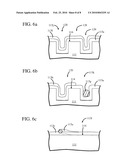
[0026]FIG. 6a is a side view of a cleat having multiple material layers, in accordance with the invention, bonded to a tread surface of the footwear of FIG. 1a.
[0027]FIG. 6b is a side view of a cleat having multiple material layers, in accordance with the invention, bonded to the corrugation of FIG. 3a.
[0028]FIG. 6c is a side view of a cleat having multiple material layers, in accordance with the invention, bonded to the tread surface and external sole liner of the footwear of FIG. 1a.
DETAILED DESCRIPTION OF THE INVENTION
[0029]FIG. 1a is a side view of footwear 110, in accordance with the invention, being worn on a foot 100. FIGS. 1b and 1c are top and bottom perspective views of footwear 110, and FIG. 1d is a bottom view of footwear 110. In this embodiment, footwear 110 includes an external sole liner 111 having a tread surface 114 and an opposed surface 115. External sole liner 111 can be manufactured in many different ways. For example, in some embodiments, external sole liner 111 is formed from a piece of flat stock material. External sole liner 111 can be formed from the piece of flat stock material in many different ways. For example, in one embodiment, external sole liner 111 is cut from the piece of flat stock material using a water cut tool. A water cut tool cuts through the flat stock material in response to flowing a stream of water at it.
[0030]External sole liner 111 is an external sole liner because it is not covered by an upper. In general, an upper for footwear includes a quarter, vamp, counter and/or lining. Hence, external sole liner 111 is an external sole liner because it is not covered by a quarter, vamp, counter and/or lining. It should be noted that, in some embodiments, tread surface 114 is smooth and, in other embodiments, tread surface 114 is not smooth. For example, in some embodiments, tread surface 114 includes one or more corrugations extending therethrough so that it is not smooth.
[0031]External sole liner 111 can have many different structures. In this embodiment, external sole liner 111 includes a single liner 111a and a single adhesive layer 112a, as indicated by an indication arrow 150. External sole liner 111 is useful as a single-use product when it includes a single sole liner. In another embodiment, such as the one indicated by indication arrow 151, external sole liner 111 includes multiple layers of liners, which are denoted as liners 111a, 111b and 111c. In this way, footwear 110 can include one or more liners. In the embodiment of indication arrow 151, liners 111a, 111b and 111c are separable from each other. In this way, footwear 110 includes a plurality of liners which are separable from each other. External sole liner 111 is useful as a multi-use product when it includes multiple sole liners, because the uppermost sole liner can be removed to expose the sole liner below it. The exposed sole liner can be adhered to foot 100 using exposed adhesion layer 112.
[0032]In this embodiment, footwear 110 includes an adhesive layer 112 carried by external sole liner 111 on opposed surface 115. In this way, footwear 110 includes an adhesive layer carried by external sole line opposed to tread surface 114. It should be noted that, in the embodiments which include multiple layers of liners, footwear 110 generally includes an adhesive layer carried by each liner. For example, in the embodiment indicated by indication arrow 150, footwear 110 includes adhesive layers 112a, 112b and 112c which are carried by liners 111a, 111b and 111c, respectively. In this way, footwear 110 includes an adhesive layer carried by each liner. In these embodiments, the adhesion layers can have the same adhesion strengths or different adhesion strengths. The adhesion strength of adhesion layers will be discussed in more detail below.
[0033]Adhesive layer 112 is generally an exposed adhesive layer because it is not covered by an upper. Hence, adhesive layer 112 is an exposed adhesive layer because it is not covered by a quarter, vamp, counter and/or lining. Having an exposed adhesive layer is useful so that a wearer of footwear 110 can adhere adhesive layer 112 to foot 100. In particular, an exposed adhesive layer is useful so that a wearer of footwear 110 can adhere adhesive layer 112 to foot sole 104. In this way, external sole liner 111 is coupled to foot 100 through adhesive layer 112. It should be noted that external sole liner 111 conforms to the shape of foot 100 in response to foot 100 being adhered to adhesive layer 112. In particular, external sole liner 111 conforms to the shape of foot sole 104 in response to foot sole 104 being adhered to adhesive layer 112. In other embodiments, external sole liner 111 is preshaped so it conforms to the shape of foot 100. In general, external sole liner 100 has a uniform thickness, but it can have a non-uniform thickness if desired. For example, external sole liner 111 typically has a non-uniform thickness when it is preshaped so it conforms to the shape of foot 100.
[0034]The adhesion strength of adhesive layer 112 can have many different values. In general, the adhesion strength typically has values the same or similar to that of surgical tape. There are many different types of surgical tape that are available, such as 3M BLENDERM Surgical Tape Clear. In some embodiments, adhesive layer 112 provides a dry adhesion strength of between about 0.25 Newtons per centimeter to about 0.75 Newtons per centimeter. In some embodiments, adhesive layer 112 provides a wet adhesion strength of between about 0.10 Newtons per centimeter to about 0.15 Newtons per centimeter. More information regarding adhesive layers and the adhesion strength of adhesive layers can be found in U.S. Pat. Nos. 6,198,016 and 6,441,092, the contents of which are incorporated herein by reference.
[0035]In this embodiment, footwear 110 includes a cleat 113 carried by external sole liner 111 proximate to tread surface 114. Cleat 113 increases the amount of traction provided by footwear 110. In general, cleat 113 provides more traction the further it extends away from tread surface 114, and cleat 113 provides less traction the closer it terminates to tread surface 114. Further, more traction is provided to footwear 110 as the number of cleats 113 included therein increases, and less traction is provided to footwear 110 as the number of cleats included therein decreases.
[0036]Cleat 113 can be carried by footwear 110 in many different ways. In this embodiment, cleat 113 is bonded to tread surface 114 so that a bonding interface 117 is formed between them, as indicated by an indication arrow 152 in FIG. 1a. In this way, cleat 113 is bonded to external sole liner 111 through a bonding interface. Cleat 113 can be bonded to external sole liner 111 in many different ways, such as by applying an adhesive layer to cleat 113 and bonding cleat 113 to tread surface 114. In this way, footwear 110 includes a cleat bonded to a tread surface.
[0037]In this embodiment, however, cleat 113 is bonded to external sole liner 111 by using screen printing. More information regarding screen printing can be found in U.S. Pat. No. 6,092,464, the contents of which are incorporated herein by reference. U.S. Pat. No. 6,092,464 discloses a way to screen print a three-dimensional raised surface having a desired shape. Hence, cleat 113 can be screen printed onto external sole liner 111 so that it extends along and away from tread surface 114. In this way, cleat 113 provides traction for footwear 110.
[0038]Cleat 113 can have many different shapes. FIG. 2a is a top view of a cleat 113a having a longitudinal shape. In this embodiment, cleat 113a is longitudinal in shape because it has a length L that is greater than its height H and width W, as indicated by an indication arrow 157. It should be noted that the view of indication arrow 157 is a cross-sectional view of cleat 113a taken along a cut-line 2-2. Cleat 113a is longitudinal in shape so that it extends along tread surface 114.
[0039]FIG. 2b is a top view of a cleat 113b positioned on tread surface 114. In this embodiment, cleat 113b is longitudinal in shape and extends along tread surface 114 to form a closed shape. In this particular embodiment, the closed shape it rectangular. However, it should be noted that the closed shape can be many other shapes. For example, FIG. 2c is a top view of a cleat 113c with a closed circular shape. FIG. 2d is a top view of a cleat 113d with a closed triangular shape. FIG. 2e is a top view of a cleat 113e with a closed diamond shape.
[0040]It should be noted that the shape of the cleat can be open, if desired. For example, in some embodiments, the cleat is shaped as indicia. The indicia can be of many different types, such as a letter and logo. Hence, the indicia can be associated with a name, such as a name of a company and sports team. Further, the indicia can be associated with a logo, such as a logo of a company and sports team. It should be noted that, when the cleat is shaped as an indicia, portions of it can have various shapes. For example, when the cleat is shaped as indicia, portions of it can be longitudinal and/or have a shape shown in any of FIGS. 2b, 2c, 2d and 2e.
[0041]In this embodiment, external sole liner 111 includes a corrugation 120 extending through tread surface 114, as shown in FIG. 1d. It should be noted that, in general, external sole liner 111 can include one or more corrugations extending therethrough. Corrugation 120 can be formed in many different ways, such as those disclosed in U.S. Pat. Nos. 5,882,462 and 6,834,525, the contents of which are incorporated herein by reference. It should be noted that adhesive layer 112 is carried by external sole liner 111 opposed to corrugation 100 when tread surface 114 includes corrugation 100. Further, adhesive layer 112 is carried by the external sole liner 111 opposed to channel 100 when tread surface 114 includes channel 100.
[0042]The corrugation(s) can extend through tread surface 114 in many different directions. For example, in the embodiment indicated by an indication arrow 153, corrugation 120 extends along a longitudinal axis of external sole liner 111. In the embodiment indicated by an indication arrow 154, corrugation 120 extends along a transverse axis of external sole liner 111. In the embodiment indicated by an indication arrow 155, corrugations 120a and 120b extend along the longitudinal and transverse axes, respectively, of external sole liner 111. In the embodiment indicated by an indication arrow 156, corrugations 120a and 120b extend at non-zero angles relative to the longitudinal and transverse axes of external sole liner 111. In this way, footwear 110 includes a plurality of channels spaced apart from each other.
[0043]FIGS. 3a, 3b and 3c are side views, taken along a cut-line 3-3 of FIG. 1d, of different embodiments of corrugation 120. In general, corrugation 120 includes a channel 121 which extends from tread surface 114 towards opposed surface 115. Corrugation 120 can have many different shapes. In FIG. 3a, corrugation 120 has a rectangular cross-sectional shape. Corrugation 120 includes opposed sidewalls 122 and 123 and a transverse wall 124 extending between opposed sidewalls 122 and 123 when channel 121 has a rectangular cross-sectional shape. In this way, channel 121 is bounded by opposed sidewalls 122 and 123, as well as transverse wall 124, when corrugation 120 has a rectangular cross-sectional shape.
[0044]In FIG. 3b, a corrugation 120a has a partially curved cross-sectional shape. Corrugation 120a includes opposed curved sidewalls 126 and 127 and transverse wall 124 extending between opposed curved sidewalls 126 and 127 when channel 121a has a partially curved cross-sectional shape. In this way, channel 121a is bounded by opposed curved sidewalls 126 and 127, as well as transverse wall 124, when corrugation 120a has a partially curved cross-sectional shape.
[0045]In FIG. 3c, a corrugation 120b has a curved cross-sectional shape. In this embodiment, corrugation 120b includes a curved wall 125 when corrugation 120b has a curved cross-sectional shape. In this way, channel 121b is bounded by curved wall 125 when corrugation 120b has a curved cross-sectional shape. It should be noted that the corrugations included with external sole liner 111 are typically of the same shape. However, in some embodiments, the corrugations included with external sole liner 111 have different shapes. For example, in one embodiment, external sole liner 111 includes corrugations 120 and 120a. In another embodiment, external sole liner 111 includes corrugations 120a and 120b. It should also be noted that the corrugations can extend in the directions indicated by indication arrows 155 and 156, wherein the corrugations extend along the transverse and longitudinal axis of footwear 100.
[0046]FIGS. 4a, 4b, 4c and 4d are side views of cleat 113a bonded to corrugation 120, in accordance with the invention. Cleat 113a can be bonded to corrugation 120 in many different ways. In the embodiment of FIG. 4a, cleat 113a extends along tread surface 114 and over channel 121. In the embodiment of FIG. 4b, cleat 113a extends along tread surface 114 and through channel 121. In particular, cleat 113a extends between opposed sidewalls 122 and 123 and above transverse wall 124. In the embodiment of FIG. 4c, cleat 113a extends along tread surface 114 and through channel 121. In particular, cleat 113a extends between opposed sidewalls 122 and 123 and engages transverse wall 124. In FIGS. 4b and 4c, cleat 113a extends inside and outside of channel 121. In FIGS. 4a, 4b and 4c, cleat 113a extends between adjacent channels. Cleat 113a is bonded to adjacent channels 121. In this way, footwear 110 includes a cleat bonded to adjacent channels.
[0047]In the embodiment of FIG. 4d, cleat 113a extends through channel 121 and engages opposed sidewalls 122 and 123, as well as transverse wall 124. However, cleat 113a does not extend along tread surface 114. Hence, in FIG. 4d, cleat 113a extends inside of channel 121. In FIG. 4d, cleat 113a does not extend inside and outside of channel 121. In FIG. 4d, cleat 113a does not extend between adjacent channels.
[0048]It should be noted that cleat 113a and corrugation 120 are shown in FIGS. 4a, 4b, 4c and 4d for illustrative purposes, and that any of the cleats discussed herein can be bonded to any of the corrugations discussed herein in the same or a similar manner. In FIG. 3b, for example, cleat 113a can extend along tread surface 114 and through channel 121a. In particular, cleat 113a can extend between opposed curved sidewalls 126 and 127 and above transverse wall 124. Further, in FIG. 3c, cleat 113a can extend along tread surface 114 and through channel 121b. In particular, cleat 113a can extend through channel 121b so it engages curved wall 125.
[0049]In accordance with the invention, the cleat tapers in response to being bonded to the corrugation. The cleat tapers in response to being bonded to the corrugation because a portion of it extends further away from external sole liner 111 than another portion. The cleat tapers in response to being bonded to the corrugation because a portion of it extends outwardly from tread surface 114 and further away from external sole liner 111 than another portion. For example, in FIGS. 4a, 4b and 4c, a portion 128 of cleat 113a extends further away from external sole liner 111 than a portion 129 of cleat 113a. In particular, cleat 113a tapers in response to being bonded to corrugation 120 because portion 128 extends outwardly from tread surface 114 and further away from external sole liner 111 than portion 129. Hence, cleat 113a tapers in response to extending over or through channel 121.
[0050]FIG. 5a is a top view of a cleat 113h, in accordance with the invention, bonded to tread surface 114. In this embodiment, cleat 113h includes cleats 113b and 113c positioned on tread surface 114, wherein cleats 113b and 113c have closed shapes. In this embodiment, cleat 113c is positioned within cleat 113b so that cleat 113b surrounds cleat 113c. In this way, cleat 113h includes a first material layer which surrounds a second material layer. It should be noted that cleat 113h can be formed by screen printing. For example, cleat 113h can be formed by screen printing cleats 113b and 113c on tread surface 114. Cleats 113b and 113c can be screen printed together or separately.
[0051]FIG. 5b is a side view of a cleat 113i, in accordance with the invention, bonded to tread surface 114. In this embodiment, cleat 113i includes cleats 113a and 113c bonded to tread surface 114, wherein a portion of cleat 113a extends over cleat 113c. In this embodiment, cleat 113c is closed in shape and cleat 113a is longitudinal in shape. The portion of cleat 113a that extends over cleat 113c is tapered. In this way, cleat 113i includes first and second material layers, wherein the second material layer tapers in response to extending over the first material layer. Another embodiment of a cleat that is the same or similar to cleat 113i is shown in FIG. 6c. It should be noted that cleat 113i can be formed by screen printing. For example, cleat 113i can be formed by screen printing cleats 113a and 113c on tread surface 114. In particular, cleat 113c is screen printed onto tread surface 114, and then cleat 113b is screen printed on tread surface 114 and cleat 113c.
[0052]FIG. 6a is a side view of a cleat 113j, in accordance with the invention, bonded to corrugation 120. In this embodiment, cleat 113j includes cleat 113a positioned on tread surface 114, and cleat 113f positioned on cleat 113a. In this way, cleat 113j includes first and second material layers, and a portion of cleat 113f extends over a portion of cleat 113a. Cleat 113j extends over channel 121, and portion 128 of cleat 113j extends further away from external sole liner 111 than portion 129 of cleat 113j. In this way, cleat 113j includes first and second material layers positioned proximate to each other, wherein the first and second material layers taper in response to extending over a channel. Cleats 113a and 113f extend along tread surface 114 and through channel 121. In this way, cleat 113j includes a first material layer with a portion that extends inside a channel and a portion that extends outside the channel.
[0053]FIG. 6b is a side view of a cleat 113k, in accordance with the invention, bonded to corrugation 120. In this embodiment, cleat 113j includes cleat 113a positioned on tread surface 114, and cleat 113b positioned on cleat 113a. Further, cleat 113k includes cleat 113g positioned on cleat 113a in channel 121. In this way, cleat 113k includes first and second material layers, and a portion of cleats 113b and 113g extend over a portion of cleat 113a. Cleat 113k extends over channel 121, and portion 128 of cleat 113k extends further away from external sole liner 111 than portion 129 of cleat 113k. In this way, cleat 113k includes first and second material layers positioned proximate to each other, wherein the first and second material layers taper in response to extending over a channel. Cleats 113a and 113b extend along tread surface 114 and through channel 121, and cleat 113g extends through channel 120. In this way, cleat 113k includes a first material layer with a portion that extends inside a channel and a portion that extends outside the channel.
[0054]FIG. 6c is a side view of a cleat 113l, in accordance with the invention, bonded to tread surface 114 and external sole liner 111. In this embodiment, cleat 1131 includes cleats 113a and 113c bonded to tread surface 114, wherein a portion of cleat 113c extends over cleat 113a. The portion of cleat 113c that extends over cleat 113a is tapered. In this way, cleat 113l includes first and second material layers, wherein the second material layer tapers in response to extending over the first material layer.
[0055]It should be noted that footwear 100 can include many other features. For example, in some embodiments, footwear 100 includes a medicament. The medicament can be included with footwear 100 in many different ways. For example, in some embodiments, the medicament is carried by adhesive layer 112. The medicament can be of many different types, such as those used to reduce bacteria.
[0056]Footwear 100 is useful in many different situations. For example, footwear 100 can be used in nail solons and fitness centers, as well as in correctional and medical facilities. It should be noted that footwear 100 can be adhered to another garment, such as a shoe. Further, footwear 100 can be adhered to a clean room suit, which is often worn by users in a clean room environment.
[0057]The embodiments of the invention described herein are exemplary and numerous modifications, variations and rearrangements can be readily envisioned to achieve substantially equivalent results, all of which are intended to be embraced within the spirit and scope of the invention.
User Contributions:
comments("1"); ?> comment_form("1"); ?>Inventors list |
Agents list |
Assignees list |
List by place |
Classification tree browser |
Top 100 Inventors |
Top 100 Agents |
Top 100 Assignees |
Usenet FAQ Index |
Documents |
Other FAQs |
User Contributions:
Comment about this patent or add new information about this topic:
| People who visited this patent also read: | |
| Patent application number | Title |
|---|---|
| 20150028694 | POWER COUPLINGS IN TRANSMITTERS FOR WIRELESS POWER TRANSMISSION |
| 20150028693 | PHOTOCONTROL FOR LUMINAIRE CONSUMES VERY LOW POWER |
| 20150028692 | SYSTEMS AND METHODS FOR REMOTE OR LOCAL SHUT-OFF OF A PHOTOVOLTAIC SYSTEM |
| 20150028691 | NON-CONTACT POWER FEEDING APPARATUS AND NON-CONTACT POWER FEEDING METHOD |
| 20150028690 | POWER SUPPLY DEVICE, POWER RECEIVING DEVICE, POWER SUPPLY METHOD, POWER RECEIVING METHOD, AND PROGRAM |
Images included with this patent application:
 |  |
 |  |
 |  |
 |  |
 |
| New patent applications in this class: | |
| Date | Title |
|---|---|
| 2016-12-29 | Article of footwear with flexible reinforcing plate |
| 2016-07-07 | Article of footwear with soil-shedding performance |
| 2016-07-07 | Article of footwear with soil-shedding performance |
| 2016-07-07 | Laminate and method for making laminate |
| 2016-06-23 | Soil-shedding article of footwear, and method of using the same |
| Top Inventors for class "Boots, shoes, and leggings" | |
| Rank | Inventor's name |
|---|---|
| 1 | Frederick J. Dojan |
| 2 | Michael A. Aveni |
| 3 | Perry W. Auger |
| 4 | Sergio Cavaliere |
| 5 | Lee D. Peyton |