Patent application title: SYSTEM AND METHOD FOR OBJECTIVE SELF-DIAGNOSIS OF MEASUREMENT DEVICE CALIBRATION CONDITION
Inventors:
Pierre Delajoud (Neuilly Sur Seine, FR)
Martin Girard (Paradise Valley, AZ, US)
Assignees:
FLUKE CORPORATION
IPC8 Class: AG21C1700FI
USPC Class:
702183
Class name: Measurement system performance or efficiency evaluation diagnostic analysis
Publication date: 2009-12-17
Patent application number: 20090312984
Inventors list |
Agents list |
Assignees list |
List by place |
Classification tree browser |
Top 100 Inventors |
Top 100 Agents |
Top 100 Assignees |
Usenet FAQ Index |
Documents |
Other FAQs |
Patent application title: SYSTEM AND METHOD FOR OBJECTIVE SELF-DIAGNOSIS OF MEASUREMENT DEVICE CALIBRATION CONDITION
Inventors:
Pierre Delajoud
Martin Girard
Agents:
DORSEY & WHITNEY LLP;INTELLECTUAL PROPERTY DEPARTMENT
Assignees:
FLUKE CORPORATION
Origin: SEATTLE, WA US
IPC8 Class: AG21C1700FI
USPC Class:
702183
Patent application number: 20090312984
Abstract:
A measurement system uses a plurality of transducers that may differ from
each other in at least one respect, such as having different operating
principles or being made by different manufacturers. Respective
measurement values obtained from the transducers are applied to a
processor which provides a measured value based on the measurement values
from a plurality of the transducers. The processor also provides
information about the calibration drift of each of the transducers based
upon a comparison between the measurement value obtained from the
transducer to a value obtained from a combination of respective
measurement values obtained from a plurality of the transducers. The
calibration drift information provides an objective evaluation about the
calibration condition of each of the transducers. When a transducer is
determined to be outside of its calibration tolerance, a calibration
needed alert occurs.Claims:
1. A method of measuring a parameter, comprising:making a plurality of
measurements at least some of which are measured independently of the
other measurements;deriving a measured value from at least some of the
plurality of measurements; andusing the plurality of measurements to
determine whether the accuracy of at least some of the plurality of
measurements is less than a predetermined accuracy.
2. The method of claim 1 wherein the act of making a plurality of measurements comprises making a plurality of measurements using a respective plurality of measurement devices having different principles of operation.
3. The method of claim 1 wherein the act of making a plurality of measurements comprises making a plurality measurements using a respective plurality of measurement devices manufactured by different manufacturers.
4. The method of claim 1 wherein the act of deriving a measured value from at least some of the plurality of measurements comprises:discarding at least one of the measurements based on the value obtained from the at least one measurement compared to a combination of the values obtained from at least some of the other measurements; andusing the remaining measurement to provide the measured value.
5. The method of claim 1 wherein the act of deriving a measured value from at least some of the plurality of measurements comprises averaging the plurality of measurements.
6. The method of claim 1 wherein the act of using the plurality of measurements to determine whether the accuracy of at least some of the plurality of measurements is less than a predetermined accuracy comprises comparing the respective values obtained from each of the plurality of measurements to a value determined from a combination of values obtained from the plurality of measurements.
7. The method of claim 6 wherein the value determined from a combination of the plurality of measurements comprises an average of the respective values obtained from plurality of measurements.
8. The method of claim 1, further comprising providing a calibration alert if the accuracy of at least some of the plurality of measurements is less than the predetermined accuracy.
9. The method of claim 1 wherein the act of making a plurality of measurements comprises making a plurality of fluid pressure measurements.
10. The method of claim 1 wherein the act of making a plurality of measurements comprises making a plurality of electrical measurements.
11. The method of claim 1 wherein the act of making a plurality of measurements comprises making each of the plurality of measurements in the same measurement environment.
12. A measurement system, comprising:a plurality of measurement devices at least some of which are different from each other, each of the measurement devices providing a respective measurement value; anda processor coupled to receive the measurement values from the plurality of measurement devices, the processor being operable to derive a measured value from at least some of the plurality of measurement values, the processor further being operable to provide information about calibration drift of at least some of the plurality of calibration devices.
13. The measurement system of claim 12 wherein the plurality of measurement devices have respective principles of operation that differ from each other.
14. The measurement system of claim 12 wherein the plurality of measurement devices comprises measurement devices manufactured by different manufacturers.
15. The measurement system of claim 12 wherein the processor is operable to compare each of the measurement values from the respective measurement devices to a value derived from a combination of the measurement values from a plurality of the respective measurement devices, and, based on the comparison, to select at least one of the measurement values to ignore in determining the measured value.
16. The measurement system of claim 12 wherein the value derived from a combination of the measurement values obtained from a plurality of the respective measurement devices comprises an average of the measurement values obtained from a plurality of the respective measurement devices.
17. The measurement system of claim 12 wherein the processor is operable to provide information about calibration drift of at least some of the plurality of calibration devices by comparing the respective values obtained from each of the plurality of measurement devices to a value derived from a combination of the values obtained from the plurality of the respective measurement devices.
18. The measurement system of claim 17 wherein the value derived from a combination of the values obtained from the plurality of the respective measurement devices comprises an average of the values obtained from the plurality of the respective measurement devices.
19. The measurement system of claim 12 wherein the information about calibration drift of at least some of the plurality of calibration devices provided by the processor comprises a calibration alert.
20. The measurement system of claim 12 wherein each of the measurement devices comprise a respective pressure transducer.
21. The measurement system of claim 12 wherein each of the measurement devices comprise a respective electrical measurement device.
22. The measurement system of claim 12 wherein the plurality of measurement devices are in the same measurement environment.
23. The measurement system of claim 22 wherein the each of the measurement devices comprises a respective pressure transducer, and the measurement system further comprises a housing to which each of the pressure transducers are fluidly coupled in a symmetrical manner, the housing having a pressure port in fluid communication with each of the pressure transducers.
24. The measurement device of claim 23 wherein the pressure port is equidistant from all of the pressure transducers.
25. The measurement device of claim 23 wherein the pressure transducers are positioned so that the gravity effect on the overall measurement device remains regardless of the orientation of the measurement device.
Description:
TECHNICAL FIELD
[0001]This application relates to measurement systems and methods, and, more particularly, to a measurement system and method that allows calibration periods to be extended with very low risk of overextending without impairing measurement accuracy.
BACKGROUND OF THE INVENTION
[0002]Every measurement device drifts or changes with time. As a result of this drift, every measurement device must be recalibrated regularly to assure that measurements made by the device remain within a tolerance that is normally defined by specifications of the measurement device. Failure to calibrate the measurement device before it is out of tolerance may have negative consequences, including recalling or questioning all measurements made by the device since the last calibration. A failure to calibrate can also result in erroneous measurements in the field, which can be disastrous in terms of quality, cost, safety, etc. It is therefore highly desirable to calibrate at sufficiently short recalibration intervals.
[0003]Although a short recalibration interval is desirable to ensure accurate measurements, a recalibration interval that is shorter than necessary increases calibration frequency thus increasing direct and indirect calibration costs, such as instrument downtime, shipping and associated risks. Currently, the recalibration interval is usually based on past experience with similar devices, and it is selected based on the largest anticipated calibration drift of the measurement device.
[0004]The difficulty in selecting an adequately short recalibration interval is exacerbated by the fact that calibration drift occurs in different measurement devices at different rates. Therefore, the recalibration interval of a measurement device is usually statistically determined on the basis of the calibration drift history of a population of similar devices. An interval is then chosen that provides an acceptable likelihood of in-tolerance conditions at calibration. Given the very high cost of out of tolerance conditions at recalibration, the interval must be conservative, and it therefore causes a majority of measurement devices to be calibrated earlier than necessary thereby unnecessarily increasing costs. In addition, the predictive statistical method has no chance of identifying outliers whose behavior deviates significantly from predicted behavior.
[0005]There is therefore a need for a system and method that provides an alternative to predictive recalibration interval selection so that a longer recalibration interval can be used without risking out of tolerance conditions at recalibration.
SUMMARY
[0006]A measurement system and method makes a plurality of measurements at least some of which are measured independently of the other measurements. The system then derives a measured value from a combination of values obtained from at least some of the plurality of respective measurements. The plurality of measurements obtained by the system and method are also used to provide information about calibration drift of measurement devices used to make the measurements, such as an indication of whether the accuracy of at least some of the plurality of measurements is less than a predetermined accuracy.
BRIEF DESCRIPTION OF THE DRAWINGS
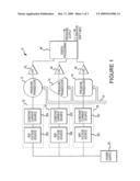
[0007]FIG. 1 is a block diagram of a pressure measurement system according to one embodiment of the invention.
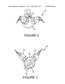
[0008]FIG. 2 is a side isometric view of a pressure measurement device according to one embodiment of the invention.
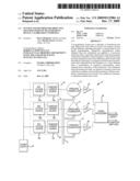
[0009]FIG. 3 is a bottom isometric view of the pressure measurement device of FIG. 2.
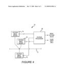
[0010]FIG. 4 is a block diagram of an electrical measurement system according to one embodiment of the invention.
DETAILED DESCRIPTION
[0011]A measurement system 10 according to one embodiment of the invention is shown in FIG. 1. The system 10 is used for measuring pressure, but the principle of operation could be used for a system measuring any other kind of physical variable, such as temperature, or a characteristic of an electrical signal, such a voltage or frequency. The system 10 includes three pressure transducers 12, 14, 16 having respective inlet ports that are connected to a common pressure conduit 18. The pressure transducers 12, 14, 16 are powered by respective current sources 22, 24, 26 that are powered by a common power supply 28. Each of the current sources 22, 24, 26 includes a reference voltage source 30a,b,c that provides a regulated voltage, and a constant current source 32a,b,c that converts a reference voltage from the voltage source 30a,b,c to a corresponding current. However, different types of power supplies may be used depending upon the nature of measurement devices used in a system. Also, although the system 10 uses three pressure transducers 12, 14, 16 and associated components, only two pressure transducers or more than three pressure transducers could be used. However, three pressure transducers 12, 14, 16 is the minimum number of transducers that make it possible to identify a pressure transducer providing measurements that differ markedly from the others.
[0012]Each of the pressure transducers 12, 14, 16 provides an analog output voltage that corresponds to the pressure in the conduit 18 measured by the transducers 12, 14, 16. The output voltages are applied to respective analog-to-digital ("A/D") converters 42, 44, 46, which output respective digital output signals indicative of the pressures measured by the transducers 12, 14, 16, respectively. The digital output signals from the A/D converters 42, 44, 46 are applied to a digital processor 48, which may be, for example, a computer system running an application program performing a suitable analysis algorithm, as discussed in greater detail below. The digital processor 48 determines and provides an indication of not only a measured pressure, but also information relating to the calibration drifts of the pressure transducers 12, 14, 16.
[0013]A variety of algorithms can be used to determine the measured pressure and the calibration drift. A value for the measured pressure can be obtained, for example, from an average or a weighted average of the pressure measurements obtained from each of the pressure transducers 12, 14, 16. In some embodiments, a measured pressure value is obtained from the measurements of only two of the pressure transducers 12, 14, 16, and the value measured by one of the transducers 12, 14, 16 is ignored because, for example, the pressure value differs excessively from the pressure measured by the other two pressure transducers 12, 14, 16. The calibration drift can be obtained by a variety of means. For example, the value of the pressure measured by each of the pressure transducers 12, 14, 16 can be compared to the average or a weighted average of the measured pressure values. If the value of the pressure measured by any of the transducers 12, 14, 16 differs from the average by more than a specific value, a calibration alert indicating that the transducers 12, 14, 16 need to be calibrated can be provided. Other means of detecting that calibration drift has reached a specific value will be apparent to one skilled in the art.
[0014]The transducers 12, 14, 16 may be identical to each other, or two or more may be different from each other in a variety of respects. For example the pressure transducers 12, 14, 16 may have different principles of operation, such as the transducer 12 having a diaphragm instrumented with resistance strain gauges, the transducer 14 having a diaphragm instrumented with resonant beam force sensor, and the transducer 16 having a spring compressed or tensioned responsive to pressure changes and instrumented with a position sensor that senses the position of a movable end of the spring. As another example, the pressure transducers 12, 14, 16 may all use a common principle of operation, but they may be made by different manufacturers. Alternatively, they may all use a common principle of operation and be made by the same manufacturer, but be from different manufacturing lots. Other variations between the pressure transducers 12, 14, 16 are also possible. Using pressure transducers 12, 14, 16 that differ from each other in some respects tends to lessen the probability that their calibration drifts will match each other.
[0015]An embodiment of a pressure sensor 50 is shown in FIGS. 2 and 3. The pressure sensor 50 includes three pressure transducers 52, 54, 56 that may be identical to each other or they may be different, as explained above. Each of the transducers 52, 54, 56 includes electrical terminals 58 through which the transducer 52, 54, 56 is powered and from which a signal indicative of the measured pressure can be obtained. The transducers may be symmetrically positioned in three 90 degree axes about a pressure port 60 (FIG. 3) that extends from a spherical housing 62. Also, a temperature probe 64 (FIG. 2) may be positioned equidistant from all of the transducers 52, 54, 56. Symmetrically positioning the transducers 52, 54, 56 on a sphere equidistant from the test pressure port ensures that they are all exposed to the pressure in the same manner even if the pressure changes so that valid comparisons can be made between the pressures measured by the transducers. Orienting the transducers in three 90 degree axes provides independence of the overall sensor from orientation and gravity effects. In use, the pressure port 60 may face in any direction.
[0016]A measurement system 70 according to another embodiment of the invention is shown in FIG. 4. The system 70 measures the voltage on a wire 72 using three separate voltage measuring devices 74, 76, 78. Each of the voltage measuring devices 74, 76, 78 provides a respective digital output to a voltage processor 80, which uses a suitable algorithm as explained above to provide a measured voltage value and information relating to calibration drift, such as a calibration needed alarm. Again, the voltage measuring devices 74, 76, 78 may be identical to each other, or they may differ from each other in a variety of respects as previously explained. The voltage measuring devices 74, 76, 78 may be connected to the wire 72 at the same location so that they are exposed to the same measurement environment. For example, if the voltage measuring devices 74, 76, 78 were connected to the wire 72 at different locations, a voltage drop might exist along the length of the wire, or a voltage could be capacitively coupled to one location on the wire 72 to a greater or less extend than to another location.
[0017]From the foregoing it will be appreciated that, although specific embodiments of the invention have been described herein for purposes of illustration, various modifications may be made without deviating from the spirit and scope of the invention. Accordingly, the invention is not limited except as by the appended claims.
User Contributions:
comments("1"); ?> comment_form("1"); ?>Inventors list |
Agents list |
Assignees list |
List by place |
Classification tree browser |
Top 100 Inventors |
Top 100 Agents |
Top 100 Assignees |
Usenet FAQ Index |
Documents |
Other FAQs |
User Contributions:
Comment about this patent or add new information about this topic:
| People who visited this patent also read: | |
| Patent application number | Title |
|---|---|
| 20130201381 | IMAGE PICKUP APPARATUS, LENS APPARATUS, AND CAMERA APPARATUS |
| 20130201380 | OPTICAL IMAGING SYSTEM AND PORTABLE TERMINAL HAVING THE SAME |
| 20130201379 | DIGITAL CAMERA AND FINDER DEVICE THEREOF |
| 20130201378 | ELECTRONIC VIEWFINDER |
| 20130201377 | MOBILE COMPUTING DEVICE WITH IMPROVED IMAGE PREVIEW FUNCTIONALITY |
Images included with this patent application:
 |  |
 |  |
| New patent applications in this class: | |
| Date | Title |
|---|---|
| 2019-05-16 | Abnormality sign notifying system, abnormality sign notifying method, and program |
| 2019-05-16 | Method of evaluating an hvac unit |
| 2017-08-17 | Systems and methods for detecting degradation of a component in an air conditioning system |
| 2016-07-14 | Anomaly diagnosis system and anomaly diagnosis method |
| 2016-06-30 | Notification apparatus usable with cooling system or other system |
| Top Inventors for class "Data processing: measuring, calibrating, or testing" | |
| Rank | Inventor's name |
|---|---|
| 1 | Lowell L. Wood, Jr. |
| 2 | Roderick A. Hyde |
| 3 | Shelten Gee Jao Yuen |
| 4 | James Park |
| 5 | Chih-Kuang Chang |