Patent application title: EXERCISE ASSEMBLY
Inventors:
IPC8 Class: AA63B2100FI
USPC Class:
482105
Class name: User manipulated force resisting apparatus, component thereof, or accessory therefor utilizing weight resistance weight worn on body of user
Publication date: 2016-06-23
Patent application number: 20160175641
Abstract:
An exercise assembly includes a sleeve that has a top end, a bottom end
and a peripheral wall extending therebetween. The top end and the bottom
end are open. The sleeve may be worn on an appendage of a user. A
plurality of pockets is coupled to an outer surface of the peripheral
wall. Each of the pockets has an upper end and a lower end. Each of the
upper ends is open. A plurality of rods has a first end, a second end and
an outer wall extending therebetween. The outer wall has a back side and
front side. Each of the upper ends of the pockets insertably receives one
of the rods such that the back side abuts the peripheral wall of the
sleeve. A selectable number of the pockets are filled with one of the
rods to establish a weight of the sleeveClaims:
1. An exercise assembly configured to add weight to appendages of a user,
said assembly comprising: a sleeve having a top end, a bottom end and a
peripheral wall extending therebetween, said top end and said bottom end
being open, said sleeve being configured to be worn on an appendage of a
user, said bottom end comprising a single cuff coupled to a main portion
of said sleeve, said single cuff having a break therein to define a pair
of free ends of said single cuff, one of said free ends defining a flap
overlapping and extendable away from another of said free ends and said
main portion of said sleeve; a plurality of pockets coupled to an outer
surface of said peripheral wall, each of said pockets having an upper end
and a lower end, each of said upper ends being open; and a plurality of
rods having a first end, a second end and an outer wall extending
therebetween, said outer wall having a back side and a front side, each
of said upper ends of said pockets insertably receiving one of said rods
such that said back side abuts said peripheral wall of said sleeve
wherein a selectable number of said pockets are filled with one of said
rods to establish a weight of said sleeve.
2. (canceled)
3. The assembly according to claim 1, wherein a coupler releasably attaching said free ends together at a selectable circumference, said coupler comprising a first mating member and a second mating member.
4. The assembly according to claim 1, wherein each of said pockets being distributed around an entire circumference of said peripheral wall, each of said pockets substantially extending between said top end and said bottom end.
5. The assembly according to claim 1, wherein said back side being flattened, said front side being convexly arcuate such that each of said rods has a semi circular cross section taken perpendicular to an axis extending through said first end and said second end.
6. An exercise assembly configured to add weight to appendages of a user, said assembly comprising: a sleeve having a top end, a bottom end and a peripheral wall extending therebetween, said top end and said bottom end being open, said sleeve being configured to be worn on an appendage of a user, said bottom end comprising a single cuff coupled to a main portion of said sleeve, said single cuff having a break therein to define a pair of free ends of said single cuff, one of said free ends defining a flap overlapping and extendable away from another of said free ends and said main portion of said sleeve; a coupler releasably attaching said free ends together at a selectable circumference, said coupler comprising a first mating member and a second mating member; a plurality of pockets coupled to an outer surface of said peripheral wall, each of said pockets having an upper end and a lower end, each of said upper ends being open, each of said pockets being distributed around an entire circumference of said peripheral wall, each of said pockets substantially extending between said top end and said bottom end; a plurality of rods having a first end, a second end and an outer wall extending therebetween, said outer wall having a back side and front side, said back side being flattened, said front side being convexly arcuate such that each of said rods has a semi circular cross section taken perpendicular to an axis extending through said first end and said second end, each of said upper ends of said pockets insertably receiving one of said rods such that said back side abuts said peripheral wall of said sleeve wherein a selectable number of said pockets are filled with one of said rods to establish a weight of said sleeve.
Description:
BACKGROUND OF THE DISCLOSURE
Field of the Disclosure
[0001] The disclosure relates to exercise devices and more particularly pertains to a new exercise device for imparting weight to a user's appendages.
SUMMARY OF THE DISCLOSURE
[0002] An embodiment of the disclosure meets the needs presented above by generally comprising a sleeve that has a top end, a bottom end and a peripheral wall extending therebetween. The top end and the bottom end are open. The sleeve may be worn on an appendage of a user. A plurality of pockets is coupled to an outer surface of the peripheral wall. Each of the pockets has an upper end and a lower end. Each of the upper ends is open. A plurality of rods has a first end, a second end and an outer wall extending therebetween. The outer wall has a back side and front side. Each of the upper ends of the pockets insertably receives one of the rods such that the back side abuts the peripheral wall of the sleeve. A selectable number of the pockets are filled with one of the rods to establish a weight of the sleeve.
[0003] There has thus been outlined, rather broadly, the more important features of the disclosure in order that the detailed description thereof that follows may be better understood, and in order that the present contribution to the art may be better appreciated. There are additional features of the disclosure that will be described hereinafter and which will form the subject matter of the claims appended hereto.
[0004] The objects of the disclosure, along with the various features of novelty which characterize the disclosure, are pointed out with particularity in the claims annexed to and forming a part of this disclosure.
BRIEF DESCRIPTION OF THE DRAWINGS
[0005] The disclosure will be better understood and objects other than those set forth above will become apparent when consideration is given to the following detailed description thereof. Such description makes reference to the annexed drawings wherein:
[0006] FIG. 1 is a front view of an exercise assembly according to an embodiment of the disclosure.
[0007] FIG. 2 is a top perspective view of an embodiment of the disclosure.
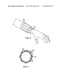
[0008] FIG. 3 is a side perspective view of an embodiment of the disclosure.
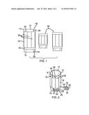
[0009] FIG. 4 is a cross sectional view taken along line 4-4 of FIG. 2 of an embodiment of the disclosure.
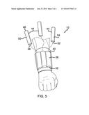
[0010] FIG. 5 is a front perspective view of an embodiment of the disclosure.
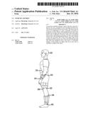
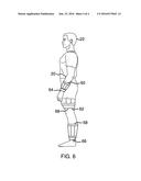
[0011] FIG. 6 is an in-use view of an embodiment of the disclosure.
DESCRIPTION OF THE PREFERRED EMBODIMENT
[0012] With reference now to the drawings, and in particular to FIGS. 1 through 6 thereof, a new exercise device embodying the principles and concepts of an embodiment of the disclosure and generally designated by the reference numeral 10 will be described.
[0013] As best illustrated in FIGS. 1 through 6, the exercise assembly 10 generally comprises a sleeve 12 has a top end 14, a bottom end 16 and a peripheral wall 18 extending therebetween. The top end 14 and the bottom end 16 are open. The sleeve 12 may be worn on an appendage 20 of a user 22. The bottom end 16 comprises a cuff 24. The cuff 24 has a break 26 therein to define a pair of free ends 28 of the cuff 24.
[0014] A coupler 30 releasably attaches the free ends 28 together at a selectable circumference. The coupler 30 retains the sleeve 12 on the user's appendage 20. The coupler 30 comprises a first mating member 32 and a second mating member 34. The first 32 and second 34 mating members may each comprise a hook and loop fastener.
[0015] A plurality of pockets 36 is coupled to an outer surface 38 of the peripheral wall 18. Each of the pockets 36 has an upper end 40 and a lower end 42. Each of the upper ends 40 is open. Additionally, each of the pockets 36 is distributed around an entire circumference of the perimeter wall 18. The pockets 36 each substantially extend between the top end 14 and the bottom end 16.
[0016] A plurality of rods 44 is provided. Each of the rods 44 has a first end 46, a second end 48 and an outer wall 50 extending therebetween. The outer wall 50 has a back side 52 and front side 54. The back side 52 is flattened and the front side 54 is convexly arcuate. Each of the rods 44 has a semi circular cross section taken perpendicular to an axis extending through the first end 46 and the second end 48. The upper end 40 of each of the pockets 36 insertably receives one of the rods 44 such that the back side 52 abuts the peripheral wall 18 of the sleeves 12. A selectable number of the pockets are filled with one of the rods to establish a weight of the sleeves.
[0017] The sleeve 12 is one of a plurality of sleeves 56. The plurality of sleeves 56 includes a pair of ankle sleeves 58, a pair of wrist sleeves 60 and a pair of thigh sleeves 62. Each of the ankle 58, wrist 60 and thigh 62 sleeves may be worn on the user's wrists 64, ankles 66 and upper thighs 68.
[0018] In use, selected ones of the ankle 58, wrist 60 and thigh 62 sleeves are worn on the associated user's appendages 20. A selected number of the rods 40 are positioned in each of the sleeves 12 worn by the user 22. The selected sleeves 12 may have varying numbers of rods 40 positioned therein in order to provide differing amounts of weight on the user's wrists 64, ankles 66 and thighs 68.
[0019] With respect to the above description then, it is to be realized that the optimum dimensional relationships for the parts of an embodiment enabled by the disclosure, to include variations in size, materials, shape, form, function and manner of operation, assembly and use, are deemed readily apparent and obvious to one skilled in the art, and all equivalent relationships to those illustrated in the drawings and described in the specification are intended to be encompassed by an embodiment of the disclosure.
[0020] Therefore, the foregoing is considered as illustrative only of the principles of the disclosure. Further, since numerous modifications and changes will readily occur to those skilled in the art, it is not desired to limit the disclosure to the exact construction and operation shown and described, and accordingly, all suitable modifications and equivalents may be resorted to, falling within the scope of the disclosure. In this patent document, the word "comprising" is used in its non-limiting sense to mean that items following the word are included, but items not specifically mentioned are not excluded. A reference to an element by the indefinite article "a" does not exclude the possibility that more than one of the element is present, unless the context clearly requires that there be only one of the elements.
User Contributions:
Comment about this patent or add new information about this topic:
Images included with this patent application:
 |  |
 |  |
 |
| Similar patent applications: | |
| Date | Title |
|---|---|
| 2015-12-03 | Exercise assembly |
| 2016-07-14 | Exercise machine with a detachable stabilizing support assembly having adjustable positions |
| 2016-07-07 | Interchangeable resistance tube assembly |
| 2016-06-30 | Exercise platform system |
| 2016-06-30 | Exercise apparatus with exercise use verification function and verifying method |
| New patent applications in this class: | |
| Date | Title |
|---|---|
| 2016-05-12 | Variable weight toning strap |
| 2016-03-24 | Garment with weighted elastic portion |
| 2015-11-26 | Exercise sled and backpack combination |
| 2015-05-21 | Weighted sleeve |
| 2014-11-27 | Adjustable off-set weighted exercise method and apparatus |
| Top Inventors for class "Exercise devices" | |
| Rank | Inventor's name |
|---|---|
| 1 | William T. Dalebout |
| 2 | Scott R. Watterson |
| 3 | Raymond Giannelli |
| 4 | Leao Wang |
| 5 | Bruce Hockridge |