Patent application title: REFRIGERATED DISPLAY CABINET
Inventors:
IPC8 Class: AA47F304FI
USPC Class:
62255
Class name: Refrigeration display type with air controlling or directing means
Publication date: 2016-06-23
Patent application number: 20160174735
Abstract:
Refrigerated display cabinet (1), of the type comprising a display area
(2) for the food products (3), comprising supports (4) and/or shelves (5)
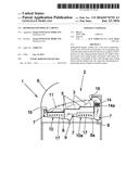
and which may comprise a full or partial cover (6), cleaning liquid
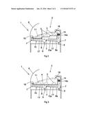
sprayers (7), liquid collection means and cooling means associated with
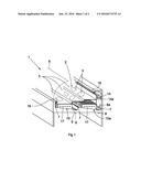
means for generating a circulating air flow (11) through said cooling
means and the display area (2), where the circulating flow-generating
means comprise reversible means.Claims:
1. Refrigerated display cabinet (1), of the type comprising a display
area (2) for the food products (3), which comprises a full or partial
cover (6) that may comprise cleaning liquid sprayers (7), liquid
collection means and cooling means associated with means for generating a
circulating air flow (11) through said cooling means and the display area
(2), characterised in that the circulating flow-generating means (11)
comprise reversible means.
2. Refrigerated display cabinet (1), according to claim 1, characterised in that the reversible means comprise, at least, two impellers (14, 14a) that alternatively impel the flow in opposite directions associated with corresponding opposing end openings (16) disposed in the display area (2).
3. Refrigerated display cabinet (1), according to claim 1, characterised in that the reversible means comprise, at least, a reversible direction impeller associated with corresponding opposing end openings (16) disposed in the display area (2).
4. Refrigerated display cabinet (1), according to any of claims 2, characterised in that each impeller (14, 14a) comprises, at least, one fan.
5. Refrigerated display cabinet (1), according to claim 2, characterised in that the impellers (14, 14a) comprise speed controllers.
6. Refrigerated display cabinet (1), according to claim 1, characterised in that the cooling means comprise, at least, two cooling elements (10, 10a) that function independently.
7. Refrigerated display cabinet (1), according to claim 6, characterised in that the liquid collection means comprise two inclined collectors (8, 8a) connected to drains (9) disposed underneath the supports (4) and/or shelves (5), wherein the sprayers (7) and cooling elements (10, 10a) are disposed between said inclined collectors (8, 8a) and said supports (4) and/or shelves (5), wherein the openings (16) are disposed on the ends of said supports (4) and/or shelves (5).
8. Refrigerated display cabinet (1), according to claim 7, characterised in that the cooling elements (10, 10a) comprise upright trapezoidal fins (17) resting levelly on the inclined collectors (8, 8a) of the container (2),
9. Refrigerated display cabinet (1), according to claim 8, characterised in that the supports (4) and/or shelves (5) fully or partially rest on the fins (17) of the cooling elements (10, 10a).
10. Refrigerated display cabinet (1), according to any of claims 3, characterised in that each impeller (14, 14a) comprises, at least, one fan.
11. Refrigerated display cabinet (1), according to claim 3, characterised in that the impellers (14, 14a) comprise speed controllers.
Description:
[0001] This application claims the benefit of, and priority to Spanish
Patent Application Number 201431919 filed on Dec. 23, 2014 entitled,
"REFRIGERATED DISPLAY CABINET", the content of which is relied upon and
incorporated herein by reference in its entirety.
DESCRIPTION
[0002] 1. Object of the Invention
[0003] The present invention relates to a refrigerated display cabinet having characteristics for improving efficiency, consumption and the temperature gradients in its interior and for preserving the quality of the food during chilling and defrost periods.
[0004] 2. Background of the Invention
[0005] Three types of refrigerated display cabinets are currently known in the state of the art: contact refrigeration display cabinets, static refrigeration display cabinets and forced air refrigeration display cabinets. In the first type, contact refrigeration display cabinets, the product displayed in the display area is cooled exclusively by conduction, on being physically in contact with a metallic base cooled by a coil, generally made of copper, extending along its inner face in contact therewith. This system is practically obsolete, since it only partially cools the products disposed on the bottom tray and does not cool the products that are not in contact with this display area. Another type comprises static refrigerated display cabinets, which generally have a construction morphology were the cold-producing element is an evaporator having a copper radiator and aluminium fins with cubic morphology, disposed on the upper rear part of the tray where the food products are displayed--an area usually occupied by the display cabinet operator--and transfers said cold through a grille. The drawback of these types of display cabinets is that, in general, due to their construction format, the product displayed covers these outlet holes and prevents the optimum distribution of cold throughout the display surface, generating temperature differences of more than 10.degree. C. between the area nearest and farthest from the evaporator, said difference being greater during scheduled stops to defrost the evaporator. These temperature differences reduce the useful life of the food products displayed, ultimately giving rise to economic losses.
[0006] In order to minimise these problems, the third type of display cabinets were built: forced air refrigerated display cabinets. In this type of display cabinet, which has a similar configuration to the foregoing and the same evaporator with cubic morphology, means were added to generate a circulating air flow--fans--through the evaporator and the food product display area, enveloping it, said air flow having the purpose of equating the temperatures at the front and rear of the display area. However, these refrigerated display cabinets, while reducing the temperature gradient to a margin of between five and eight degrees centigrade, do not satisfactorily equate the temperatures, since the cold air emitted is heated as it flows towards the absorption area which, on reaching the collection area, does not maintain the product at the temperature desired by the operator, a problem that worsens during scheduled defrost periods.
[0007] Some or all of these display cabinets may incorporate optional internal irrigation and cleaning systems, which are configured and scheduled solely for internal cleaning purposes.
DESCRIPTION OF THE INVENTION
[0008] The refrigerated display cabinet of the invention remediates the technical problem raised. The display cabinet in question is of the forced air type, comprising a food product display area where supplementary supports and/or shelves may be disposed, and the display area of which may incorporate is full or partial cover, usually transparent, and may optionally comprise liquid sprayers coupled to the corresponding internal cleaning network, means for collecting the liquids that drip from the food products and/or spray nozzles, and cooling means associated with means for generating a circulating air flow through said cooling means that ensure an optimal and homogeneous temperature in the display area.
[0009] In accordance with the invention, the circulating air flow comprises reversible means, such that the flow may circulate in opposite directions and the coldest air coming directly from the cooling means does not always flow out from the same side nor always returns through the same side of the display area, favouring the generation of temperature gradients, but rather the direction of flow is reversed by detection and/or scheduling thereof, so that the coldest air flows out of the side where a higher temperature is envisaged or detected, returning in turn through the opposite side, thereby homogenising the temperatures throughout the display area and directly achieving better preservation of the products displayed.
[0010] In addition, the cooling means may be double and may function independently, for example two evaporators, each connected to a different compressor unit in the event of using cooling gas compression and evaporation circuits. This allows independent defrosting of the two evaporators, due to which at least one would always be operational, preventing the temperature of the products from rising and minimising temperature fluctuations during defrost cycles.
BRIEF DESCRIPTION OF THE DRAWINGS
[0011] FIG. 1 shows a partial perspective view of the display cabinet of the invention, wherein the products appear displayed on shelves;
[0012] FIG. 2 shows a side view of the display cabinet of the invention shown in FIG. 1; and
[0013] FIG. 3 shows a side view of a variant of the display cabinet of the invention wherein the products appear displayed on a support in the background.
DESCRIPTION OF A PRACTICAL EMBODIMENT OF THE INVENTION
[0014] The refrigerated display cabinet (1) of the invention is of the type comprising a display area (2) where the food products (3) are displayed, which may comprise a horizontal support (4) as shown in FIG. 3 and/or shelves (5) as shown in FIGS. 1 and 2, on which to arrange said products (3). Said display area (2) may comprise a full or partial cover (6), usually transparent, liquid sprayers (7) coupled to the corresponding cleaning network, liquid collection means with drains (9) for draining the liquids that drip from the products (3) and/or spray nozzles (7), in addition to cooling means associated with means for generating a circulating air flow (11) through said cooling means and the display area (2).
[0015] With this general configuration and in accordance with the invention, the means for generating a circulating flow comprise reversible means, so that the circulating air flow (11) may circulate in opposite directions, compensating the unfavourable gradients produced when the circulating flow (11) is always in the same direction. The reversal of the circulating flow (11) is governed by the corresponding controller, not shown, associated with temperature sensors, not shown either, distributed throughout the display area (2) and/or time bases of the controller itself. FIGS. 2 and 3 show the flow circulating (11) in both directions.
[0016] The reversible means comprise, at least, two impellers (14, 14a) that alternatively impel the flows in opposite directions disposed in the display area (2), so that the circulating flow (11) flows out or in alternatively through said openings (16) in accordance with their specific direction of flow. One of the two options would be selected and even combinations of the two options if deemed necessary. In either case, each impeller may have various fans and/or speed controllers to precisely adjust the necessary flow.
[0017] Furthermore, the cooling means comprise, at least, two cooling elements (10, 10a) that operate independently. This makes it possible to independently defrost each cooling element, so that there will always be one cooling element producing cold and preventing the temperature of the products from rising. This will also make it possible to extend the duration of the defrost cycles, as the products are not at risk (3), and therefore ensure more effective defrosting, which will result in an increase in efficiency and reduction in consumption, using the sprayers (7) for dragout during defrosting. The cooling elements (10, 10a) typically comprise the evaporators of a compressor cooler unit and their operation is also governed by the controller. An unexpected additional advantage resulting from the arrangement of the two independent cooling elements (10, 10a) is that they may have less production capacity, reducing their height to make more room for the display area (2), compared to display cabinets having a single cooling element.
[0018] Said cooling elements (10, 10a) are disposed on the liquid collection means, which comprise two inclined collectors (8, 8a) disposed at the bottom underneath the supports (4) and/or shelves (5). These inclined collectors (8, 8a) and said supports (4) and/or shelves (5) are connected to the corresponding drains (9). The sprayers (7) and cooling elements (10, 10a) are disposed between these inclined collectors (8, 8a) and said supports (4) and/or shelves (5), while the openings (16) are disposed at the ends of said supports (4) and/or shelves (5). The cooling elements (10, 10a) preferably comprise upright trapezoidal fins (17), as shown in the figures, for resting levelly on the collectors (8, 8a). In this document, `resting levelly` is understood to mean that the upper parts of the fins (17) are substantially coplanar and horizontal, whereon the supports (4) and/or shelves (5) may rest fully or partially, which will also give rise to the transmission of cold directly by conduction via the supports (4) and/or shelves (5) towards the display area (2).
[0019] Having sufficiently described the nature of the invention and the manner in which to put it into practice, it is hereby stated that the indications mentioned above and represented in the attached drawings are susceptible to changes in detail, provided that they do not alter the basic principle.
User Contributions:
Comment about this patent or add new information about this topic:
Images included with this patent application:
 |  |
 |
| Similar patent applications: | |
| Date | Title |
|---|---|
| 2016-06-16 | Refrigerated enclosure with health related functions |
| 2019-05-16 | Refrigerant hammer arrestor and refrigerant loop incorporating that refrigerant hammer arrestor |
| 2019-05-16 | Heat exchange device, refrigeration system, and heat exchange method |
| 2016-06-09 | Refrigerator with improved uv treatment chamber |
| 2016-12-29 | Refrigeration device for container |
| New patent applications in this class: | |
| Date | Title |
|---|---|
| 2016-04-21 | Refrigerated sales furniture |
| 2015-10-22 | Refrigerated display case with temperature controlled shelves |
| 2015-03-05 | Air duct for refrigeration case |
| 2014-09-18 | Merchandiser with louver retainer |
| 2013-10-17 | Convertible temperature-controlled display case |
| Top Inventors for class "Refrigeration" | |
| Rank | Inventor's name |
|---|---|
| 1 | Michael F. Taras |
| 2 | Alexander Lifson |
| 3 | Koji Yamashita |
| 4 | Hiroyuki Morimoto |
| 5 | Patrick J. Boarman |