Patent application title: IMPACT ACTIVATED EXPLOSION SIMULATOR
Inventors:
IPC8 Class: AF41J524FI
USPC Class:
273378
Class name: Aerial projectile game; game element (e.g., target, etc.) or accessory therefor other than projector or projectile, per se target indication by movement of target or target having indicating means
Publication date: 2016-06-16
Patent application number: 20160169637
Abstract:
An apparatus and method for indicating an impact of a projectile. The
apparatus comprises a compressed gas container having a plurality of
ports adapted to exhaust a compressed gas contained within the gas
container and an actuator adapted to detect an impact from a projectile.
The apparatus further comprises a valve located between the gas container
and the plurality of ports activated by the actuator in response to the
impact and an audio indicator activated by the actuator in response to
the impact. The method for indicating an impact of a projectile
comprising detecting an impact of a projectile at a actuator, activating
a valve located between a gas container and a plurality of ports in
response to the impact upon the actuator and producing an audio indicator
in response to the impact upon the actuator.Claims:
1. An apparatus for indicating an impact of a projectile comprising: a
compressed gas container having a plurality of ports associated therewith
adapted to exhaust a compressed gas contained within said gas container;
an actuator adapted to receive an impact from a projectile; a valve
located between said gas container and said plurality of ports activated
by said actuator in response to said impact; and an audio indicator
activated by said actuator in response to said impact.
2. The apparatus of claim 1 further including an outer body having an impact location corresponding to said actuator.
3. The apparatus of claim 2 wherein said outer body includes suspending straps.
4. The apparatus of claim 2 wherein said ports are located on a top of said outer body.
5. The apparatus of claim 1 wherein said ports include a visual indicator therein adapted to be released upon discharge of said compressed gas therethrough.
6. The apparatus of claim 5 wherein said visual indicator comprises particles.
7. The apparatus of claim 5 wherein said visual indicator comprises a powder.
8. The apparatus of claim 1 wherein said audio indicator is selected from the group consisting of a speaker, horn or siren.
9. The apparatus of claim 1 further comprising a fill port for introducing a compressed gas into said gas container.
10. The apparatus of claim 9 wherein said fill port comprises a one way valve.
11. The apparatus of claim 1 wherein said valve is adapted to release a burst of said compressed gas contained within said gas container upon being activated by said actuator.
12. The apparatus of claim 11 wherein said burst comprises a single burst.
13. The apparatus of claim 12 further including a charging handle adapted to reset said valve after said single burst.
14. The apparatus of claim 1 wherein said actuator is calibrated to be activated by an impact energy of between 5 and 27 J.
15. The apparatus of claim 1 further including a safety key for interrupting a connection between said actuator and said valve.
16. A method for indicating an impact of a projectile comprising detecting an impact of a projectile at an actuator; activating a valve located between a gas container and a plurality of ports in response to said impact upon said actuator; and producing an audio indicator in response to said impact upon said actuator.
Description:
BACKGROUND OF THE INVENTION
[0001] 1. Field of Invention
[0002] The present invention relates to the field of indicators in general and in particular to a method and apparatus for indicating an impact from a projectile to a user.
[0003] 2. Description of Related Art
[0004] In many industries, it is desirable to provide an indication of an impacted projectile. In particular, in various fields where firearms operation is necessary, training is frequently undertaken to ensure that the personnel in that field have the required skill. Such training commonly involves the personnel shooting at targets to improve their aim and/or reaction times.
[0005] One difficulty with common target shooting is that such targets are commonly static with little or no features to replicate shooting at a real target. Such targets may therefore be less effective at training personnel to shoot at targets which may react explosively or loudly.
SUMMARY OF THE INVENTION
[0006] According to a first embodiment of the present invention there is disclosed an apparatus for indicating an impact of a projectile comprising a compressed gas container having a plurality of ports adapted to exhaust a compressed gas contained within the gas container and a actuator adapted to detect an impact from a projectile. The apparatus further comprises a valve located between the gas container and the plurality of ports activated by the actuator in response to the impact and an audio indicator activated by the actuator in response to the impact.
[0007] The apparatus may further include an outer body having an impact location corresponding to the actuator. The outer body may include suspending straps. The ports may be located on a top of the outer body.
[0008] The ports may include a visual indicator therein adapted to be released from said ports upon discharge of the compressed gas therethrough. The visual indicator may comprise particles. The visual indicator may comprise a powder. The audio indicator may be selected from the group consisting of a speaker, horn or siren.
[0009] The apparatus may further include a fill port for introducing a compressed gas into the gas container. The fill port may comprise a one way valve.
[0010] The valve may be adapted to release a burst of the compressed gas contained within the gas container upon being activated by the actuator. The burst may comprise a single burst.
[0011] The apparatus may further include a charging handle adapted to reset the valve after the single burst. The actuator may be calibrated to be activated by an impact energy of between 5 and 27 J. The apparatus may further include a safety key for interrupting a connection between the actuator and the valve.
[0012] According to a further embodiment of the present invention there is disclosed a method for indicating an impact of a projectile comprising detecting an impact of a projectile at an actuator, activating a valve located between a gas container and a plurality of ports in response to the impact upon the actuator and producing an audio indicator in response to the impact upon the actuator.
[0013] Other aspects and features of the present invention will become apparent to those ordinarily skilled in the art upon review of the following description of specific embodiments of the invention in conjunction with the accompanying figures.
BRIEF DESCRIPTION OF THE DRAWINGS
[0014] In drawings which illustrate embodiments of the invention wherein similar characters of reference denote corresponding parts in each view,
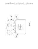
[0015] FIG. 1 is a perspective view of an apparatus for indicating an impact of a projectile according to a first embodiment of the present invention.
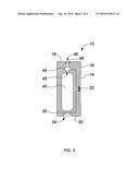
[0016] FIG. 2 is a cross-sectional view of the apparatus of FIG. 1 as taken along the line 2-2.
[0017] FIG. 3 is a diagram of pneumatic control system of the apparatus of FIG. 1.
[0018] FIG. 4 is a front view of the apparatus of FIG. 1 while releasing a visual indicator from the ports in response to an impact.
DETAILED DESCRIPTION
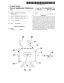
[0019] Referring to FIGS. 1 and 2, an apparatus for indicating the impact of a projectile according to a first embodiment of the invention is shown generally at 10. The apparatus comprises an outer body 12 having a target zone 14 on one surface thereof. The target zone 14 includes an actuator 22 for sensing an impact upon the target zone 14. The actuator 22 is adapted to trigger the release of a compressed gas as well as an auditory signal as will be more fully described below.
[0020] The outer body 12 may be of any suitable shape as desired by a user to simulate the appearance of the real world intended target. As illustrated in FIG. 1, the outer body 12 may be substantially rectangular have a front face 16 which includes the target zone. The outer body 12 also includes a top surface 18 and a bottom surface 20. The outer body 12 may be formed of any suitable material such as foam, plastic, metal or the like so as to achieve the desired appearance by a user.
[0021] Turning now to FIG. 2, a cross section of the apparatus 10 is illustrated. The apparatus 10 includes a compressed gas container 40 within the outer body. The gas container 40 may be of any suitable type for holding a compressed gas and may be formed of a rigid or semi rigid material such as metal, plastic or the like. In particular the gas container 40 may be adapted to contain any inert propellant such as, by way of non-limiting example, nitrogen, high pressure air or liquid carbon dioxide. The gas container 40 may have a fill nozzle or port 42 extending through one side of the outer body 12 as illustrated in FIG. 1. The fill port 42 may be of any suitable type for interfacing with a source of compressed gas as are commonly known. The gas container includes a valve 44 located at an outlet 45 thereof. The valve 44 is configured to release the gas contained within the gas container when the actuator 22 detects an impact of a predefined amount upon the target area 14. The valve 44 may be adapted to release a single burst from the gas chamber in response to an impact upon the target zone 14. Thereafter a charging handle 32 is provided to reset the valve and permit subsequent releases. A safety key or switch 34 may also be provided to prevent activation of the valve 44 and audio indicator 30 in undesirable locations.
[0022] The outer body includes a plurality of ports 46 along the top surface 18 thereof. The ports 46 may include a visual indicator material 48 therein which will be sprayed or distributed by the gas exiting the ports 46. The visual indicator material may be selected to be any suitable particulate material such as powders, particles or the like. In some embodiments, the visual indicator material may non-flammable liquids such as water or water soluble paints.
[0023] As illustrated in FIG. 2, the apparatus 10 also includes an audio indicator 30 through a bottom port 24 in the bottom surface 20 of the outer body 12. It will be appreciated that as illustrated in FIG. 3, the audio indicator 30 may comprise at least one port in the apparatus 10 which is in fluidic communication with the gas container 40. In operation, the valve 44 or 44b is adapted to release a burst of pressurized gas through the port to create an indicating sound. The sound emitted from the apparatus may be of any sound desired by the user, such as a bang, siren or the like. Accordingly, the size and shape of the port will be selected to produce such a sound according to known principles. The sound may also be of a volume desired to correspond to the situation being simulated.
[0024] Optionally, as illustrated in FIG. 2, the audio indicator may optionally comprise a speaker, horn, siren or any other suitable device for creating a sound to a user. The audio indicator 30 is also interconnected with the actuator 22 so as to be activated when the actuator 22 detects an impact upon the target zone 14.
[0025] Optionally, the outer body 12 may also include straps 26 for securing the outer body to an object. In particular, the straps 26 may be formed of any suitable material, such as, by way of non-limiting example, nylon plastic or the like and may be fastened by any suitable connectors, such as, by way of non-limiting example, buckles, snaps, hook and loop connectors or ties.
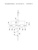
[0026] Turning now to FIG. 3, pneumatic schematic of the system is illustrated. The apparatus 10 may include an audio compressed gas container 40a and valve 44a as well as an audio compressed gas container 40b and valve 44b associated with each of the ports 46 and audio indicator 30, respectively. The fill port 42 may be in communication with each of the compressed gas containers 40a and 40b through a common input line 56. The input line 56 includes a check valve 52 and a pressure indicator 54 such as a gauge or the like to indicate a pressurized status of the system. Each of the compressed gas containers 40a and 40b may also include associated check valves 50a and 50b, respectively so as to prevent escape of compressed gas as well as to isolate each container from each other. As illustrated, the actuator 22 is connected to the valve 44 and the audio indicator 30 to activate them upon receipt of a sufficient impact in the target zone 14. The connection is a physical one as set out below although it will also be appreciated that electrical connections may also be utilized. The size of the impact required may be determined by a user to correspond to the impact of any desired projectile with which the system is to be utilized including airsoft guns, paintball markers, non-penetrating target ammunition as are commonly known. In particular, the actuator 22 may be selected to be activated upon receipt of an impact on the target zone 14 of between 5 and 27 joules.
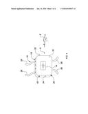
[0027] In operation, a user may fill the gas container 40 through the fill port 42. When a user desires to use the apparatus 10, they may reset the valve 44 with the charging handle 32 and unlocks the apparatus 10 with the safety key 34. After this a user, may fire a target projection 6 from a practice weapon 8 towards the apparatus 10. If the target zone 14 is struck the valve 44 is activated to release the compressed gas from the gas container 40 through the ports 46 thereby distributing the visual indicator material 48 into the air as illustrated in FIG. 4. Furthermore the audio indicator 30 is also activated to omit the sound desired.
[0028] The actuator 22, gas containers 40a and 40b and valves 40a and 40b are illustrated as separate components in the above description for ease of explanation. It will also be appreciated that the actuator 22, gas containers 40a and 40b and valves 40a and 40b may be formed as a common article such that the interconnections therebetween illustrated in FIG. 3 are direct physical connections such that the actuator 22 comprises a switch or button adapted to actuate the valves.
[0029] While specific embodiments of the invention have been described and illustrated, such embodiments should be considered illustrative of the invention only and not as limiting the invention as construed in accordance with the accompanying claims.
User Contributions:
Comment about this patent or add new information about this topic:
Images included with this patent application:
 |  |
 |  |
 |
| Similar patent applications: | |
| Date | Title |
|---|---|
| 2016-01-28 | Six-piece coordinated motion puzzle |
| 2015-12-17 | Talent portfolio simulation |
| 2016-06-16 | Target actuation system |
| New patent applications in this class: | |
| Date | Title |
|---|---|
| 2014-06-26 | Shooting target |
| 2014-05-15 | Reactive target with point of impact feedback |
| 2013-12-12 | Firearm target |
| 2013-09-05 | Shooting target, method of use, and method of manufacture |
| 2013-02-14 | Shooting target and method of manufacture |
| Top Inventors for class "Amusement devices: games" | |
| Rank | Inventor's name |
|---|---|
| 1 | Attila Grauzer |
| 2 | Peter Krenn |
| 3 | Ronald R. Swanson |
| 4 | Kyle Bateman |
| 5 | Feraidoon Bourbour |