Patent application title: MODULAR DECORATIVE WALL PANEL
Inventors:
IPC8 Class: AE04F1308FI
USPC Class:
52 365
Class name: Including component (e.g., wall) designed to receive a disparate article having disparate article mounted thereto component having specific attachment for an article comprising a horizontal, planar surface (e.g., shelf, bed) connecting feature for modular-type panels having article (e.g., cabinet, shelf bracket) attachment
Publication date: 2016-06-16
Patent application number: 20160168863
Abstract:
A modular decorative wall panel (100) comprises plurality of metal frame
(102), plurality of front panel (104), plurality of metal insert (106)
configured to assemble the plurality of metal frame (102), plurality of
mounting brackets (108) configured to couple the modular decorative wall
panel (100) onto a wall, plurality of horizontal hanging extrusion trim
(110) configured to insert into the modular decorative wall panel (100)
before mounting the modular decorative wall panel (100) onto the wall,
plurality of connector (114) configured to couple the plurality of metal
frame (102), plurality of extrusion trim (116) configured to clipped into
the plurality of connector (114).Claims:
1. A modular decorative wall panel (100) comprises: plurality of metal
frame (102); plurality of front panel (104); plurality of metal insert
(106), said plurality of metal insert (106) configured to assemble said
plurality of metal frame (102); plurality of mounting brackets (108),
said plurality of mounting brackets (108) configured to couple said
modular decorative wall panel (100) onto a wall; plurality of horizontal
hanging extrusion trim (110), said plurality of horizontal hanging
extrusion trim (110) configured to insert into said modular decorative
wall panel (100) before mounting said modular decorative wall panel (100)
onto said wall; plurality of connector (114), said plurality of connector
configured to couple said plurality of metal frame (102); and plurality
of extrusion trim (116), said plurality of extrusion trim (116)
configured to clipped into said plurality of connector (114).
2. The modular decorative wall panel (100) as claimed in claim 1, wherein each of said plurality of metal frame (102) is aluminum extrusion channel.
3. The modular decorative wall panel (100) as claimed in claim 2, wherein each of said plurality of metal frame (102) is a rectangular frame having a length of 0.8 m and a height of 0.4 m.
4. The modular decorative wall panel (100) as claimed in claim 1, wherein said plurality of metal insert (106) is L-shaped metal insert.
5. The modular decorative wall panel (100) as claimed in claim 1, further comprises plurality of holding spring bracket (120) attached at a bottom end of said plurality of front panel (104) and plurality of locking spring bracket (120') attached at a top end of said plurality of front panel (104).
6. The modular decorative wall panel (100) as claimed in claim 5, wherein each of said plurality of front panel (104) having a minimum thickness of 0.009 m.
7. The modular decorative wall panel (100) as claimed in claim 1, further comprises plurality of slot trim (122) configured to mount plurality of hanging accessories (124).
8. The modular decorative wall panel (100) as claimed in claim 7, wherein said plurality of hanging accessories (124) includes cabinet, drawer, shelf and posters.
9. The modular decorative wall panel (100) as claimed in claim 1, wherein each of said plurality of connector (114) is cast plastic bracket.
10. The modular decorative wall panel (100) as claimed in claim 1 is configured to use as a free standing partition.
11. The modular decorative wall panel (100) as claimed in claim 10, wherein said free standing partition installed on a floor and supported by plurality of side pillars.
Description:
CROSS-REFERENCE TO RELATED APPLICATIONS
[0001] This present application claims the benefit of Malaysian Patent Application No. PI 2014703716 filed on Dec. 10, 2014, the contents of which are hereby incorporated by reference.
TECHNICAL FIELD
[0002] Embodiments of the present invention relate to a wall panel, and more particularly to a modular decorative wall panel which is addable from minimum standard size.
BACKGROUND ART
[0003] A wall structure for supporting both inner and outer decorative panels to provide a versatile system for interior design is gaining importance in today's scenario. The panels are changeable and can be reversed easily to display a second surface with an alternate color or design.
[0004] Conventional wall covering materials, such as paint, tile, wallpaper and paneling, are relatively permanent once applied and, depending on the material selected, can require considerable time and expense to replace. As a result, a consumer usually selects a durable, easy to clean wall covering to maximize useful life and to minimize the need for redecorating.
[0005] U.S. Pat. No. 4,353,193 disclose a wall-mounted structure includes a support which removable holds an inner decorative panel having displays on opposite sides. The inner panel is secured to the support by a mounting means which permits the reversal of the panel to expose either side. A frame is provided with a second mounting means to hold a series of outer decorative panels which can partially or totally conceal the inner panel from view. Each decorative panel is changeable and reversible.
[0006] CA2800414 discloses a modular wall includes a plurality of inter-connectable and interchangeable wall modules. At least one of the wall modules includes a recessed, extendable piece of furniture such as a bed, desk, table, work surface or chair. When in a closed configuration, the furniture folds into or otherwise resides within a recessed pocket in the modular wall. When in the closed configuration, the outer surface of the furniture forms an exterior surface of the wall module; thereby, concealing the furniture seamlessly into the modular wall. The exterior surface can comprise one or more exterior interchangeable tiles.
[0007] In particular, at least one advantage of modular wall systems is that they are relatively easy to configure. In addition, modular wall systems can be less expensive to set up and can allow for reconfiguration more easily than more permanently constructed office dividers. For example, an organization can construct a set of offices and a conference area within a larger space in a relatively short period of time with the use of modular wall systems. If office space required some changes, the organization can readily reconfigure the space. Likewise, modular wall systems enable easy and fast installment of shelf's and/or decorative panels in home and eliminates the need of bulky and specially manufactured panels hobo installed on walls in living room or study room or bed room etc.
[0008] In general, modular wall systems include a series of individual wall modules, and/or panels). The individual wall modules are typically free-standing or rigidly attached to one or more support structures. In particular, a manufacturer or assembler can usually align and join the various wall modules together to form an office, a room, a hallway, or otherwise divide an open space.
[0009] While conventional modular wall systems can provide various advantages, such as those described above, conventional modular wall systems are limited in various other matters such as the wall panels are non-flexible the main front panels are not easily removable or interchangeable, the construction method of the panels are either slide in or interlock in other thus it is not possible to remove individual panel without removing other attached panel. Also, it is difficult to achieve future extension of the panels and to conceal wire for any additional electrical appliances once it is permanently installed. It is not possible to have various configurations with the existing panels.
[0010] In other words, the existing modular wall systems are not modular in the sense that the finishing panel cannot be removed individually, either they are slidable in horizontal direction or interlock with each other. Further, the `metal frame` is neither expandable nor able to add on after installation. Also, the conventional modular wall systems do not have a standard dimension of the panel. The existing modular wall systems have not explored the possibility of turning standard household furniture into systems furniture that can provide flexibility, mix & match finishing panels, various materials of panel that can be used in a same frame, future additional cabling work & add-on or expandable panels and features.
[0011] Accordingly, there remains a need in the prior art to have a modular decorative wall panel which overcomes the aforesaid problems and shortcomings.
[0012] However, there remains a need in the art for an improved modular decorative wall panel which is addable from a minimum standard size, provides interchangeable front panel to allow mix & match effect, and enables concealing of wiring even after installation for additional electrical appliances and capable of providing various configurations.
DISCLOSURE OF THE INVENTION
[0013] Embodiments of the present invention aim to provide a modular decorative wall panel which is flexible and addable. The modular decorative wall panel enables usage of interchangeable and wide selection of front panels including different range of materials. Further, it allows concealing wiring even after installation and recyclability of frame and panel. Also, the proposed modular decorative wall panel facilitates mounting of future electronic panel directly on the metal frame. The modular decorative wall panel is provided with the features of claim 1, however the invention may additionally reside in any combination of features of claim 1.
[0014] In accordance with an embodiment of the present invention, the modular decorative wall panel comprises plurality of metal frame, plurality of front panel, plurality of metal insert configured to assemble the plurality of metal frame, plurality of mounting brackets configured to couple the modular decorative wall panel onto a wall, plurality of hanging extrusion trim configured to insert into the modular decorative wall panel before mounting the modular decorative wall panel onto the wall, plurality of connector configured to couple the plurality of metal frame, plurality of extrusion trim configured to clipped into the plurality of connector.
[0015] In accordance with an embodiment of the present invention, the modular decorative wall panel may be used as a free standing partition. Further, the free standing partition is not required to be mounted on the wall and can be installed on floor and supported by side pillars.
[0016] In accordance with an embodiment of the present invention, each of the plurality of metal frame is an aluminum extrusion channel. Further, the plurality of metal frame is a rectangular frame having a length of 0.8 m and a height of 0.4 m.
[0017] In accordance with an embodiment of the present invention, the plurality of metal insert is L-shaped metal insert.
[0018] In accordance with an embodiment of the present invention, the modular decorative wall panel further comprises plurality of holding spring bracket attached at a bottom end of the plurality of front panel and plurality of locking spring bracket attached at a top end of the plurality of front panel.
[0019] In accordance with an embodiment of the present invention, each of the plurality of front panel having a minimum thickness of 0.009 m.
[0020] In accordance with an embodiment of the present invention, the modular decorative wall panel further comprises plurality of slot trim configured to mount plurality of hanging accessories. Preferably, the hanging accessories are, but not limited to, cabinet, drawer, shelf and posters.
[0021] In accordance with an embodiment of the present invention, wherein each of the plurality of connectors is cast plastic bracket.
[0022] While the present invention is described herein by way of example using embodiments and illustrative drawings, those skilled in the art will recognize that the invention is not limited to the embodiments of drawing or drawings described, and are not intended to represent the scale of the various components. Further, some components that may form a part of the invention may not be illustrated in certain figures, for ease of illustration, and such omissions do not limit the embodiments outlined in any way. It should be understood that the drawings and detailed description thereto are not intended to limit the invention to the particular form disclosed, but on the contrary, the invention is to cover all modification/s, equivalent/s and alternative/s falling within the scope of the present invention as defined by the appended claim. The headings used herein are for organizational purposes only and are not meant to be used to limit the scope of the description or the claim. As used throughout this description, the word "may" is used in a permissive sense (i.e. meaning having the potential to), rather than the mandatory sense (i.e. meaning must). Further, the words "a" or "an" mean "at least one" and "plurality" means "one or more" unless otherwise mentioned. Furthermore, the terminology and phraseology used herein is solely used for descriptive purposes and should not be construed as limiting in scope. Language such as "including," "comprising," "having," "containing," or "involving," and variations thereof, is intended to be broad and encompass the subject matter listed thereafter, equivalents, and additional subject matter not recited, and is not intended to exclude other additives, components, integers or steps. Likewise, the term "comprising" is considered synonymous with the terms "including" or "containing" for applicable legal purposes. Any discussion of documents, acts, materials, devices, articles and the like is included in the specification solely for the purpose of providing a context for the present invention. It is not suggested or represented that any or all of these matters form part of the prior art base or were common general knowledge in the field relevant to the present invention.
[0023] In this disclosure, whenever a composition or an element or a group of elements is preceded with the transitional phrase "comprising", it is understood that we also contemplate the same composition, element or group of elements with transitional phrases "consisting of", "consisting", "selected from the group of consisting of, "including", or "is" preceding the recitation of the composition, element or group of elements and vice versa.
DESCRIPTION OF DRAWINGS AND BEST MODE FOR CARRYING OUT OF THE INVENTION
[0024] So that the manner in which the above recited features of the present invention can be understood in detail, a more particular description of the invention, briefly summarized above, may be had by reference to embodiments, some of which are illustrated in the appended drawings. It is to be noted, however, that the appended drawing illustrate only typical embodiments of this invention and are therefore not to be considered limiting of its scope, for the invention may admit to other equally effective embodiments.
[0025] These and other features, benefits and advantages of the present invention will become apparent by reference to the following text figure, with like reference numbers referring to like structures across the views, wherein:
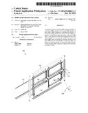
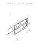
[0026] FIG. 1 illustrates a prospective view of a modular decorative wall panel in accordance with an embodiment of the present invention.
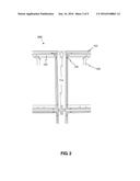
[0027] FIG. 2 illustrates the connection of plurality of metal frame of the modular decorative wall panel in accordance with an embodiment of the present invention.
[0028] FIG. 3 illustrates the connection of plurality of hanging accessories with the modular decorative wall panel in accordance with an embodiment of the present invention.
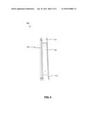
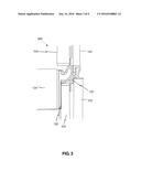
[0029] FIG. 4 illustrates the connection of plurality of front panel with the plurality of metal frame of the modular decorative wall panel in accordance with an embodiment of the present invention.
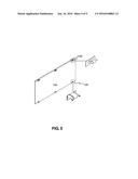
[0030] FIG. 5 illustrates attachment of plurality of holding spring bracket and plurality of locking spring bracket with the plurality of front panel of the modular decorative wall panel in accordance with an embodiment of the present invention.
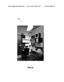
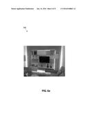
[0031] FIG. 6a shows a pictorial presentation of the modular decorative wall panel in accordance with an embodiment of the present invention.
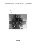
[0032] FIG. 6b shows a pictorial presentation of the modular decorative wall panel in free-style configuration in accordance with an embodiment of the present invention.
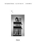
[0033] FIG. 6c shows a pictorial presentation of the modular decorative wall panel in another free-style configuration in accordance with an embodiment of the present invention.
[0034] FIG. 6d shows a pictorial presentation of the modular decorative wall panel in yet another free-style configuration in accordance with an embodiment of the present invention.
[0035] The present invention is described hereinafter by various embodiments with reference to the accompanying drawing, wherein reference numerals used in the accompanying drawing correspond to the like elements throughout the description. This invention may, however, be embodied in many different forms and should not be construed as limited to the embodiment set forth herein. Rather, the embodiment is provided so that this disclosure will be thorough and complete and will fully convey the scope of the invention to those skilled in the art. In the following detailed description, numeric values and ranges are provided for various aspects of the implementations described. These values and ranges are to be treated as examples only, and are not intended to limit the scope of the claims. In addition, a number of materials are identified as suitable for various facets of the implementations. These materials are to be treated as exemplary, and are not intended to limit the scope of the invention.
[0036] Embodiments of the present invention aim to provide a modular decorative wall panel which is flexible and addable. The present invention is able to provide an alternative and a breakthrough modular panel system to replace the traditional fix wall decorative panel or "fix furniture". The proposed modular decorative wall panel shall be able to be considered as a "loose furniture", as the same offers a new fresh look from time to time without removing any major part of the panel. It can even be considered as a mobile system as it can be dismantle and install in a new area without any complexity. The modular decorative wall panel enables usage of interchangeable and wide selection of front panels including different range of materials. Further, it allows concealing wiring even after installation and recyclability of frame and panel. Also, the proposed modular decorative wall panel facilitates mounting of future electronic panel directly on the metal frame.
[0037] Referring to the drawings, the invention will now be described in more detail. In accordance with an embodiment of the present invention, the modular decorative wall panel 100, as shown in FIG. 1, comprises plurality of metal frame 102, plurality of front panel 104, plurality of metal insert 106, plurality of mounting brackets 108, plurality of horizontal hanging extrusion trim 110, plurality of connector 114, plurality of extrusion trim 116.
[0038] In accordance with an embodiment of the present invention, each of the plurality of metal frame 102 is an aluminum extrusion channel. Further, each of the plurality of metal frame 102 is a rectangular frame having a length of 0.8 m and a height of 0.4 m. Also, each of the plurality of metal frame 102 is made up of a top frame and a side frame.
[0039] In accordance with an embodiment of the present invention, the plurality of front panel 104 is a rectangular frame having a minimum thickness of 0.009 m. Further, the plurality of front panel 104 may be a decorative frame or a wooden panel or a glass frame etc.
[0040] As shown in FIG. 1, the plurality of metal frame 102 are coupled with each other in order to form a complete structure. The plurality of metal frame 102 are coupled with each other by means of the plurality of connector 114. Further, each of the plurality of metal frame 102 is assembled by means of plurality of metal insert 106 i.e. the top frame and the side frame of each of the plurality of metal frame 102 is connected by the plurality of metal insert 106.
[0041] In accordance with an embodiment of the present invention, the each of the plurality of metal insert 106 is L-metal insert and assembles each of the plurality of metal frame 102 in order to form a rectangular frame having a length of 0.8 m and a height of 0.4 m. Further, the plurality of metal frame 102 is addable having dimensions 0.8 m length.times.0.4 m height. In other words, the modular decorative wall panel 100 may comprises of plurality of metal frame 102 coupled to each other in accordance with the overall size and configuration requirements, where each of the plurality of metal frame 102 is having a fixed dimensions of 0.8 m length.times.0.4 m height.
[0042] Further, the plurality of extrusion trim 116 clipped into the plurality of connector 114 in order to cover the side parts of the complete structure from both the side and into the plurality of connector in order to cover the top parts of the complete structure.
[0043] The plurality of front panel 104 is coupled with the plurality of metal frame 102. The coupling mechanism of the plurality of front panel 104 and the plurality of metal frame 102 is described in detail in FIG. 4. Further, before mounting the modular decorative wall panel 100 the plurality of horizontal hanging extrusion trim 110 is inserted into the modular decorative wall panel 100. Thereafter, the modular decorative wall panel 100 is mounted on a wall by means of plurality of mounting brackets 108.
[0044] In accordance with an embodiment of the present invention, the plurality of mounting brackets 108 fixed onto the plurality of metal frame 102 by means of bolt and nut. Further, the plurality of brackets 108 is, but not limited to, galvanized metal hanging brackets.
[0045] In accordance with an embodiment of the present invention, the modular decorative wall panel 100 may be used as a free standing partition. Further, the free standing partition is not required to be mounted on the wall and can be installed on a floor and/or a flat surface and supported by side pillars.
[0046] As shown in FIG. 2, the plurality of metal frame 102 is coupled by the plurality of connector 114. The plurality of connector 114 is inserted into each of the plurality of metal frame 102 in order to couple and align the neighboring plurality of metal frame 102.
[0047] In accordance with an embodiment of the present invention, the plurality of connector 114 is, but not limited to, galvanized bolt and nut. Further, the plurality of connector 114 are made of, but not limited to, plastic.
[0048] In accordance with an embodiment of the present invention, plurality of hanging accessories 124 can be coupled with the modular decorative wall panel 100. As shown in FIG. 3, the plurality of hanging accessories 124 are connected with a L-shaped aluminum frame 126 Further, the sub-assembly of the plurality of hanging accessories 124 and the L-shaped aluminum frame 126 is coupled with the modular decorative wall panel 100 by means of a plurality of slot trim 122. The plurality of slot trim 122 is provided between the pluralities of metal frame 102.
[0049] Further, the plurality of hanging accessories 124 is, but not limited to, a cabinet, a drawer, a shelf, a poster etc.
[0050] In accordance with an embodiment of the present invention, the plurality of hanging accessories 124 may slide along the slot trim 122 horizontally. Also, the plurality of hanging accessories 124 can also move in upward and downward direction, for an example, a poster can be flipped upward or downward.
[0051] As shown in FIG. 4, one of the plurality of front panel 104 is coupled with the one of the plurality of metal frame 102. Firstly, a bottom end of the front panel 104 is placed onto the extrusion channel of the metal frame 102 and then a top end of the front panel 104 is pressed inside, by a minimal force thus providing the locking effect between the extrusion channel of the metal frame 102 and the front panel 104. In this way the final assembly of the front panel 104 and the metal frame 102 is completed.
[0052] Further, the plurality of front panel 104 may be de-couple from the plurality of metal frame 102 by means of, but not limited to, manual vacuum suction.
[0053] In accordance with an embodiment of the present invention, the minimal force is applied first in a downward direction and thereafter it is applied in parallel inward direction.
[0054] In accordance with an embodiment of the present invention, the plurality of spring and hold bracket enables the coupling of the plurality of front panel 104 and the plurality of metal frame 102.
[0055] As shown in FIG. 5, plurality of holding spring bracket 120 are attached at the bottom end of the plurality of front panel 104 and plurality of locking spring bracket 120' are attached at the top end of the plurality of front panel 104 in accordance with an embodiment of the present invention. The plurality of holding spring bracket 120 and the plurality of locking spring bracket 120' facilitates easy coupling and de-coupling of the plurality of front panel 104 with the plurality of metal frame 102. Further, the plurality of holding spring bracket 120 and the plurality of locking spring bracket 120' enable firm assembly of the plurality of front panel 104 and the plurality of metal frame 102.
[0056] FIG. 6a shows a pictorial presentation 500 of the modular decorative wall panel 100 installed on a wall of a living room in accordance with an embodiment of the present invention.
[0057] FIG. 6b shows a pictorial presentation 600 of the modular decorative wall panel 100 in free-style configuration in accordance with an embodiment of the present invention.
[0058] FIG. 6c shows a pictorial presentation 700 of the modular decorative wall panel 100 in another free-style configuration in accordance with an embodiment of the present invention.
[0059] FIG. 6d shows a pictorial presentation 800 of the modular decorative wall panel 100 in yet another free-style configuration in accordance with an embodiment of the present invention.
[0060] The above-mentioned modular decorative wall panel overcomes the problems and shortcomings of the existing modular wall systems and provides numerous advantages over them. The proposed modular decorative wall panel comprises aluminum extrusion as a back frame which enables add-on of additional panels and provides flexibility to the whole structure. Further, the aluminum frame has a profile to provide griping groove in order to facilitate the front panel spring bracket to sit and lock in. Also, the proposed modular decorative wall panel have metal brackets which enables hassle free installation of the structure. The disclosed modular decorative wall panel allows removal of front panel directly and/or individually without removing the next panel. Due to the flexibility and extendibility, the disclosed modular decorative wall panel can be applied to, but not limited to, TV mounted wall panel, study area, wall mounted displays panel, book shelf, and decorative features wall panel.
[0061] In addition to the aforesaid advantageous applications of the disclosed modular decorative wall panel, the proposed modular decorative wall panel comprises of following key merits:
[0062] The proposed modular panel is addable from a minimum standard size of 0.8 m length.times.0.4 m height and may be coupled together to form a desired size of modular wall panel.
[0063] Interchangeable front panel which facilitates mix and match effect.
[0064] Allow for conceal wiring even after installation for any additional of electrical appliances.
[0065] Enable user to alter, expand and to add on accessories e.g. cabinet, shelf, drawer etc. in order to provide a fresh look from time to time.
[0066] Various configuration shall be easy to achieve as the proposed panel is based on a complete modular panel system.
[0067] The exemplary implementation described above is illustrated with specific shapes, dimensions, and other characteristics, but the scope of the invention also includes various other shapes, dimensions, and characteristics. For example, particular shape and size and attachment of the panel to the frame and the frame size itself may vary. Also, the cable connection for electricity supply varies as per the number of electrical appliances coupled with the modular decorative wall panel. The components as described in the present invention could be manufactured in various other ways and could include various other materials.
[0068] Similarly, the exemplary implementations described above include illustration that there would be a flexibility and expandability on systems, interchangeable and wide selection including different materials of front panels, conceal wiring after installation, complete knock down concept, installation friendly, recyclability of frame and panels. Also, lighting box can be inserted into the panels to provide ambient environment, cabinet, drawers, shelf and other accessories can be easily mount to the panels using a separate slot in aluminum extrusion, all the mounted items can be move to new position at any point of time and electronic gadgets e.g. clock, radio, photos displays can be inserted inside the front panel.
[0069] Various modifications to these embodiments are apparent to those skilled in the art from the description and the accompanying drawings. The principles associated with the various embodiments described herein may be applied to other embodiments. Therefore, the description is not intended to be limited to the embodiments shown along with the accompanying drawings but is to be providing broadest scope of consistent with the principles and the novel and inventive features disclosed or suggested herein. Accordingly, the invention is anticipated to hold on to all other such alternatives, modifications, and variations that fall within the scope of the present invention and appended claim.
User Contributions:
Comment about this patent or add new information about this topic:
Images included with this patent application:
 |  |
 |  |
 |  |
 |  |
 |  |
| New patent applications in this class: | |
| Date | Title |
|---|---|
| 2015-12-24 | Apparatuses and methods for connecting modular office furniture components |
| 2015-10-22 | Construction kit consisting of wall elements and connectors to be inserted therebetween in order to erect room dividers |
| 2015-10-22 | Wall mounted assembly |
| 2014-10-09 | Wall mounted assembly |
| 2013-09-19 | Wall mounted assembly |
| Top Inventors for class "Static structures (e.g., buildings)" | |
| Rank | Inventor's name |
|---|---|
| 1 | Darko Pervan |
| 2 | Gregory F. Jacobs |
| 3 | Husnu M. Kalkanoglu |
| 4 | Ronald P. Hohmann, Jr. |
| 5 | Mark Cappelle |