Patent application title: BAG OPENING APPARATUS
Inventors:
Race Davison (Minneapolis, MN, US)
IPC8 Class: AB65D3316FI
USPC Class:
383 33
Class name: Flexible bags with means to maintain the bag mouth in an open configuration
Publication date: 2016-06-09
Patent application number: 20160159527
Abstract:
Opening and then retaining a bag in an open state is achieved by mounting
resilient straps parallel to each other on opposite sides of the bag
proximate to the bag opening. A compressive force applied to the opposite
ends of the two straps will cause them to bow outwardly and thereby open
the bag so that materials and items may be deposited in the bag. Removal
of the compressive force allows the straps to straighten, closing the
bag, so that the bag may then be sealed using any of a variety of
well-known closure mechanisms.Claims:
1. For a bag having first and second sides joined together at first and
second edges and a top, an apparatus for opening the top and holding the
top open comprising: (a) a first strap having two ends and extending
along the first side of the bag proximate the top of the bag, said first
strap having a main section which extends from the first edge to the
second edge, a stop adjacent the first edge protecting downwardly from
the main section of the first strap and an extension extending outwardly
past the first edge from the main section of the first strap; and (b) a
second strap having two ends extending along the second side of the bag
proximate the top of the bag, said second strap having a main section
which extends from the first edge to the second edge of the bag, and a
stop adjacent the first edge of the bag projecting downwardly from the
main section of the second strap wherein said first and second straps are
adapted to bow outwardly away from each other when a compressive force is
applied at the two ends of the straps and such bowing causes the top to
open and be held open.
2. The apparatus of claim 1 wherein the first and second straps are made of a resilient material which causes the straps to straighten thereby closing the top of the bag when the compressive force is no longer present.
3. The apparatus of claim 1 wherein the second strap also has an extension extending outwardly past the first edge.
4. The apparatus of claim 3 wherein the extension of the first strap and the extension of the second strap are adapted to cross each other when the compressive force is applied.
5. The apparatus of claim 1 wherein at least one of the first and second straps has a stop adjacent the second edge of the bag projecting downwardly from the main section.
6. The apparatus of claim 1 wherein at least one of the first and second straps has a stop adjacent to the second edge of the bag projecting downwardly from the main section and an extension projecting outwardly past the second edge from the main section.
7. The apparatus of claim 1 further including an engagement pad coupled to the stop.
8. The apparatus of claim 7 wherein the engagement pad wraps around the stop.
9. The apparatus of claim 7 wherein the engagement pad extends perpendicularly from the stop.
10. The apparatus of claim 7 wherein the engagement pad has a surface coated with a material which produces friction.
11. For a bag having first and second sides joined together at first and second edges and a top, an apparatus for opening the top and holding the top open comprising: (a) a first strap having two ends and extending along the first side of the bag proximate the top of the bag, said first strap having a main section which extends from the first edge to the second edge, and a stop adjacent the first edge projecting downwardly from the main section of the first strap; (b) a second strap having two ends extending along the second side of the bag proximate the top of the bag, said second strap having a main section which extends from the first edge to the second edge of the bag, and a stop adjacent the first edge of the bag projecting downwardly from the main section of the second strap; and (c) an engagement pad coupled to and extending perpendicularly from the stop of at least one of the first and second straps; wherein said first and second straps are adapted to bow outwardly away from each other when a compressive force is applied at the two ends of the straps and such bowing causes the top to open and be held open.
Description:
CROSS-REFERENCED TO RELATED APPLICATIONS
[0001] Not applicable
STATEMENT REGARDING FEDERALLY SPONSORED RESEARCH OR DEVELOPMENT
[0002] Not applicable
BACKGROUND OF THE INVENTION
[0003] I. Field of the Invention
[0004] The present invention relates to resealable plastic bags. More specifically, the present invention relates to mechanisms for opening and then holding such a plastic bag open with one hand while placing items into the bag.
[0005] II. Discussion of Related Art
[0006] Plastic bags are well known in the prior art. Some published estimates indicate more than a trillion plastic bags are used worldwide each year.
[0007] Plastic bags are popular for many reasons. They are inexpensive to produce in a variety of sizes. They are easily labeled. They are generally moisture impervious. As such, when the bags are sealed, items in the bag are protected from moisture from the outside. Likewise, when moist items or even liquids are placed in the bag and the bag is properly sealed, moisture cannot escape.
[0008] One suitable mechanism for sealing a plastic bag well known in the prior art is known as a zip-lock. An example of such a zip-lock is shown in FIG. 1. As illustrated in FIG. 1, the opening 7 of the bag 1 has two sides 2 and 4 which are brought into parallel alignment with each other. Side 2 has a receiving structure 6 extending along the entire length of side 2. The receiving structure 6 has an elongate channel 8 defined by a pair of walls 10 and 12. Each wall has a locking element 14 extending toward the center of the channel 8. Side 4 has an elongate projection 18 extending the entire length of side 4 and comprising a neck 20 and a head 22. The head 22 is wider than the neck 20 such that ledges 24 and 26 exist at the intersection of the head 22 and neck 20. The head 22 is sized to be forced into the elongate channel 8 such that the ledges 24 and 26 engage the locking elements 14 to capture the head 22 in the receiving structure 6. The tolerances are such that no substantial amount of fluid can pass through the opening of the bag when the elongate projection 18 is fully mated with the elongate receiving structure 6. The bag can be opened by pulling the head 22 out of the elongate channel 8. The bag is resealed by inserting the head 22 back into the elongated channel 22 along the entire length of the opening.
[0009] Bags having the zip lock closure mechanism disclosed above are used for a variety of purposes. In the kitchen, such bags are used to store foods, marinate meats, store mixtures including liquids such as soups, chili and gravy, among a variety of other tasks. Such bags are used to store baby food, baby supplies and diapers (wet or dry). Such bags are used in the shop to store small parts (such as screws, nails, nuts, bolts and washers), tools and paint brushes, even when wet with paint. Such bags are also used to store cleaning supplies and chemicals, and chemicals used to treat lawns and swimming pools. The utility of such bags makes them well suited for a variety of uses.
[0010] Unlike other plastic containers having rigid walls, plastic bags have thin, flexible walls. This offers a number of advantages related to compact storage. However, there is also one significant disadvantage. Holding the bag open when placing items in the bag can be a problem. This is particularly true when placing items in the bag (like a wet paint brush or wet paint roller or a soiled baby diaper) when it is undesirable for a portion of the item to contact with the outside of the bag, structures surrounding the baa or the clothing or skin of the person using the bag. This is also true when trying to deposit liquids or powders in a bag without spilling. Thus, there is a real need for a mechanism which permits a bag to be held open with one hand so the other hand of the user may be employed to place or pour items into the bag.
SUMMARY OF THE INVENTION
[0011] The present invention is used in conjunction with a plastic bag having a mechanism that is able to seal and reseal the bag. The present invention comprises a pair of straps adhered to opposite sides of the bag proximate the bag opening and the mechanism used to seal and reseal the bag. The straps extend substantially the entire width of the bag and at least one of the straps may be provided with at least one end extending beyond an edge of the bag. The straps also each have a downwardly extending stop adjacent at least one edge of the bag. A stabilization pad may be placed over the outside edge of the stop. The straps may also include a living hinge or be made of a material which is of a thickness that causes the two straps to bow outwardly in the middle away from each other when a compressive force is applied to the two ends of the straps.
[0012] When in use, the stops of the straps along one edge of the bag are placed in contact with the edge of a surface such as a table top, counter top or sink. The user, using one hand, then pushes on the opposite end of the two straps creating a compressive force between the surface and the user's hand. This causes the straps to bow outwardly away from each other and the bag to open. One or more items may then be placed in the bag. If the bag is sufficiently narrow, this compressive force may be applied by squeezing the two ends of the straps between the thumb and forefinger of one hand of the user. When the compressive force is removed, the straps return back to a straight, rather than bowed, orientation drawing the bag closed. The bag is then sealed using the zip lock or similar bag sealing mechanism.
BRIEF DESCRIPTION OF DRAWINGS
[0013] FIG. 1 is a cross sectional view which shows a bag sealing mechanism well known in the prior art.
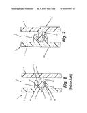
[0014] FIG. 2 is a cross sectional view like that of FIG. 1 to which an embodiment of a mechanism for holding the bag open has been added.
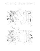
[0015] FIG. 3 is a first side elevational view of the embodiment shown in FIG. 2.
[0016] FIG. 4 is a side view of the strap shown in FIG. 3.
[0017] FIG. 5 is a second side elevational view of the embodiment shown in FIG. 2.
[0018] FIG. 6 is a side view of the strap shown in FIG. 5.
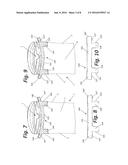
[0019] FIG. 7 is a first side view of a first alternative embodiment.
[0020] FIG. 8 is a side view of the strap shown in FIG. 7.
[0021] FIG. 9 is a second side view of the first alternative embodiment shown in FIG. 7.
[0022] FIG. 10 is a side view of the strap shown in FIG. 9.
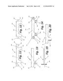
[0023] FIG. 11 is a side view of a first strap of a second alternative embodiment.
[0024] FIG. 12 is a side view of a second strap of the second alternative embodiment of FIG. 11.
[0025] FIG. 13 is a side view of the strap shown in FIG. 4 with an engagement pad coupled to the stop.
[0026] FIG. 14 is a side view of the strap shown in FIGS. 8 and 18 with engagement pads coupled to the stops.
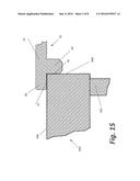
[0027] FIG. 15 is a side elevational view showing how the working end of the straps of FIGS. 3, 4, 7-10 or 13 and 14 cooperate with a tabletop, countertop or inside edge of a sink.
[0028] FIG. 16 is a top view showing how the working end of the straps shown in FIGS. 3, 4, 7-10, 13 and 14 cooperate with a tabletop, countertop or inside edge of a sink before the bag is opened.
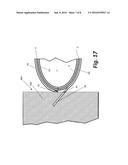
[0029] FIG. 17 is a top view like that of FIG. 16 but with the bag open.
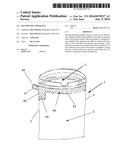
[0030] FIG. 18 is a top view showing how the working end of the straps shown in FIGS. 11 and 12 cooperate with a tabletop, countertop or inside edge of a sink with the bag opened.
[0031] FIG. 19 is a top view of the embodiment shown in FIG. 3 with an engagement pad coupled to the stops.
[0032] FIG. 20 is a side view of one of the straps and the engagement pad shown in FIG. 19.
DETAILED DESCRIPTION OF THE PREFERRED EMBODIMENT
[0033] The following discussion is presented to enable a person skilled in the art to make and use the present teachings. Various modifications to the illustrated embodiments will be readily apparent to those skilled in the art, and the principles described herein may be applied to other embodiments and applications without departing from the present invention. Thus, the present invention is riot intended to be limited to embodiments shown, but is to be accorded the widest scope consistent with the principles and features disclosed herein. The following detailed description is to be read with reference to the figures, in which like elements in different figures have like reference numerals. The figures, which are not necessarily to scale, depict selected embodiments and are not intended to limit the scope of the present invention. Skilled artisans will recognize many useful alternatives to the teachings and the examples provided herein falling within the scope of the invention exist and may be employed without deviating from the invention.
[0034] FIGS. 2-6 are presented to show a first embodiment of the present invention. These drawings show a bag 1 having sides 2 and 4 which are bonded together at edges 3 and 5. The top 7 is able to open and close and is adapted to allow items to be placed into or removed from the bag 1. In close proximity to top 7 is a zip lock style sealing mechanism comprising a receiving structure 6 formed as a part of or attached to side 2 and a projection 18 formed as a part of or attached to side 4, The receiving structure 6 is elongate and extends substantially the entire width of side 2 from edge 3 to edge 5. Likewise, the projection 18 is elongate and extends substantially the entire width of side 4 of the bag 1 from edge 3 to edge 5. The projection 18 is mated with the receiving structure along the entire width of the bag as illustrated in FIG. 2 to seal the opening 7. To open the bag 1, the projection 18 is pulled out of the receiving structure 6. Bags having a receiving structure and project different than those specifically shown in FIG. 2 are well known in the prior art. The reader should therefore understand that any suitable receiving structure and projection, and any other closure mechanism, is with the scope of the invention and there is no intention to limit the scope of the invention to the specific closure mechanism shown.
[0035] FIGS. 2-6 also show features that permit the bag 1 to be readily opened and held open using one hand of a user. These features include a strap 40 adhered to or otherwise coupled to side 2 of the bag 1 and a strap 50 adhered to or otherwise coupled to side 4 of the bag. Straps 40 and 50 may also be integrally formed with the bag 1. As shown in FIGS. 3 and 4, strap 40 includes a main section 42 which extends from edge 3 to edge 5 and is mounted proximate the top opening 7 of the bag. The strap 40 also includes a stop 44 adjacent edge 3 of the bag 1 which projects downwardly from the main section 42. Stop 44 has an engagement surface 45 which extends generally parallel to edge 3. Strap 40 also includes an extension 46 which extends outwardly past the edge 3 of the bag 1 from the main section 42 and stop 44 of the strap 40. Extension 46 has a bottom engagement surface 47.
[0036] As shown in FIGS. 5 and 6, strap 50 has a main section 52 which extends the width of side 4 between edges 3 and 5. The strap 50 has a stop 54 adjacent edge 3. Stop 54 has an engagement surface 56. Engagement surface 56 is generally parallel to edge 3 and engagement surface 45 of stop 44.
[0037] FIGS. 7-10 show a second embodiment in which straps 140 and 150 have the same shape. Strap 140 is coupled to side 2 of the bag 1 while strap 150 is coupled to side 4 of the bag 1. As shown in FIGS. 7 and 8, strap 140 has a main section 142 extending between two stops 144 and 144'. The stops 144 and 144' each have an engagement surface 145 and 145' parallel to or along the same line as the associated edge 3 or 5 of bag 1. The strap 140 also has extensions 146 and 146' extending beyond the sides 3 and 5 of the bag 1. The extensions 146 and 146' have lower engagement surfaces 147 and 147'. As shown in FIGS. 9 and 10, strap 150 has a main section 152, stops 154 and 154' at opposite ends of the main section and extensions 156 and 156' extending beyond the edges 5 and 3 from the main section 152 and stops 154 and 154'. The stops 154 and 154' have outer engagement surfaces 155 and 155'. The extensions 156 and 156' have lower engagement surfaces 157 and 157'.
[0038] FIGS. 11 and 12 each show another embodiment of the straps. The strap 240 shown in FIG. 11 is intended to replace strap 140 shown in FIG. 7 and mounted at the same location shown in FIG. 7 on side 2 of bag 1. Likewise, the strap 250 shown in FIG. 12 is intended to replace strap 150 shown in FIG. 9 and mounted to the bag 1 at the same location. Strap 240 has a main section 242, a pair of stops 244 and 244' having engagement surfaces 245 and 245', and a pair of extensions 246 and 246' having engagement surfaces 247 and 247'. The engagement surfaces 246 and 246' also each include an arch section 248 and 248'. Strap 250 has a main section 252, and stop sections 254 and 254' having engagement surfaces 255 and 255'. Strap 250 also has extensions 256 and 256' having engagement surfaces 257 and 257'. In this embodiment, the extensions 256 and 256' are adapted to pass through the arches 248 and 248' of strap 240 shown in FIG. 11.
[0039] FIG. 13 shows still another embodiment of a strap similar to that shown in FIG. 4. In this embodiment, an engagement pad 300 has been added which wraps around the stop 44 and covers a portion of engagement surface 45. This pad may be coated with an adhesive or made of a frictitious material. This pad may also provide an increased area of thickness to the apparatus which will also inhibit slipping of the straps when engaged with a tabletop, countertop, inside edge of a sink or other stable structure. This may be achieved as shown in FIGS. 19 and 20. Here, the pad 300 is shown extending perpendicularly from the longitudinal direction of the straps 40 and 50 and the sides 2 and 4 of the bag.
[0040] FIG. 14 shows similar pads 300 and 300 coupled to the stops 155 and 155' of FIG. 10 and similar pads 302 and 302' coupled to extensions 156 and 156' so as to cover engagement surfaces 157 and 157'. Alternatively, the engagement pads, rather than wrapping around the stop may extend perpendicularly from one or both sides of the stop to provide an engagement surface which is wider than the end of the strap.
[0041] FIGS. 15-17 illustrate how the embodiments shown in FIGS. 3-6 and 7-10 are used to open and then retain the top opening 7 of the bag 1 in the open position. FIG. 15 shows a tabletop 400 supported by legs such as legs 402. While a tabletop is illustrated, any other suitable structure, such as a countertop, shelf, workbench or inside edge of a sink may be used instead. To open the bag, the strap 40 is placed in proximity to the edge of the tabletop 400 such that the engagement surface 47 of extension 46 engages the top surface 406 of the tabletop 400 and the engagement surface 45 of the stop 44 engages the edge 408 of the tabletop 400. This will similarly bring engagement surface 55 of stop 55 of strap 52 into engagement with the edge 408 of the tabletop 400. When engagement pads such as 300 are employed, the pads reside between the side edge 408 of the tabletop 400 and the engagement surfaces 45 and 55 to prevent or inhibit the engagement surfaces 45 and 55 from sliding along the tabletop 400. Likewise, pads such as 302' residing between engagement surface 47 and the top surface 406 of the tabletop 400 can help inhibit or prevent such sliding.
[0042] With the straps 40 and 50 positioned as illustrated in FIGS. 15-17, a user with her or his hand pushes on the opposite end of the straps 40 and 50. Thus, a compressive force is supplied between the tabletop 400 and the user's hand. This causes the straps 40 and 50 to bow outwardly and the bag 1 to open as shown in FIG. 17. When the bag 1 is open, engagement between the extension 46 and the tabletop prevents edge 3 of the bag 1 from falling. The user holding the other end of the straps 40 and 50 prevents edge 5 from falling. To allow the bag to close, the user relieves the compressive force and the straps 40 and 50 return to their straight, parallel orientation shown in FIG. 16.
[0043] FIG. 18 shows the embodiment of FIGS. 11 and 12 being employed with a tabletop, countertop, workbench, sink or other stable surface to hold the bag 1 open. Note how extension members 246 and 256 cross. This is because extension member 256 passes through the arch 248 of extension member 246.
[0044] Those skilled in the art will recognized from the foregoing that the straps of the various embodiments may be made of plastics, metals or other materials which are stiff enough to support the bag 1 in the open position, flexible enough to permit the strap to bow when a compressive force is applied and resilient enough to return to a straight orientation when the compressive force is removed. Those skilled in the art will also recognize that the dimensions of the strap may be altered based on the materials used and adapted for bags of varying sizes. As such, the invention is not limited to the embodiments disclosed herein, but also covers a full range of equivalents.
[0045] Further, while the drawings show the apparatus being employed in combination with a tabletop, in many situations the apparatus may be advantageously used by placing the bag in a sink with the extension members in contact with the top rim of the sink and the engagement surfaces of the stops in contact with the wall of the sink at a corner of the sink. The angle of the sink corner prevents the stops from sliding along the sink. Further, the sink will catch any spillage which may occur when placing liquids or powders in the bag.
[0046] Also, in the case of a sufficiently narrow bag, the compressive force used to open the bag and then hold it open may be supplied by the thumb and forefinger of one hand of the user. The user's other hand may then be employed to deposit material or other items into the bag.
[0047] The foregoing discussion of various embodiments of the invention is not intended to be limiting. They are instead intended to describe the invention in sufficient detail to enable one of ordinary skill in the art. The scope of the invention is only limited by the following claims.
User Contributions:
Comment about this patent or add new information about this topic:
Images included with this patent application:
 |  |
 |  |
 |  |
 |
| New patent applications in this class: | |
| Date | Title |
|---|---|
| 2018-01-25 | Bag supporting assembly |
| 2016-04-28 | Yard debris bag support device |
| 2016-03-03 | Package for paste-like products |
| 2016-01-28 | Temporary plastic bag trash receptacle |
| 2016-01-28 | Leaves and debris doorway |
| Top Inventors for class "Flexible bags" | |
| Rank | Inventor's name |
|---|---|
| 1 | Shaun T. Broering |
| 2 | Robert R. Turvey |
| 3 | Brian C. Dais |
| 4 | Bryan L. Ackerman |
| 5 | Robert W. Fraser |