Patent application title: Wireless Play Communication Wristband
Inventors:
Travis Lee Cantrell
Travis Lee Cantrell (Savage, MN, US)
IPC8 Class: AA63F924FI
USPC Class:
3408154
Class name: Communications: electrical visual indication
Publication date: 2016-06-09
Patent application number: 20160158639
Abstract:
This invention is intended to strengthen play transmission between
players and coaches before, and during plays.
The wristband is an elastic, or adjustable wristband with a clear plastic
window and LED strips or LED matrix that lights the Light Emitting Diode
(LED) next to a desired play.
The wristband is wirelessly linked to either a radio frequency panel,
bluetooth device, or infrared controller. The wristband LED's are wired
to a microcontroller, Bluetooth controller (or RF transceiver, or
Infrared controller), and a battery power source. The LED's are displayed
through the clear plastic window and the plays are slid over the top of
the LED's. The micro controller, battery and wireless controller are
contained in a velcro-enclosed, low-profile enclosure opposite the clear
plastic window.Claims:
1. A wristband for strengthening play transmission and understanding
between players and coaches during a game comprising of: (1) an elastic,
or adjustable material, with a clear plastic rectangular window
displaying LED's and corresponding plays, and a velcro enclosure opposite
the window to house the electronics, that slides over the wrist; (2) a
wired electric circuit comprising of a series of LED strips wired
together (or LED Matrix), wired to a microcontroller, which is wired to a
wireless transceiver/Bluetooth/Infrared controller and connected to a
battery power source, said electric circuit receives a signal from a
wireless device and lights a corresponding LED next to a desired play;
2. The apparatus of claim 1, wherein the notification element is in the LED format
3. The apparatus of claim 1, wherein the velcro enclosure containing the electric circuit is able to absorb shock of tackle, contact with a ball, ground, or another player.
Description:
FIELD OF THE INVENTION
[0001] This invention is a device that strengthens the play transmission and understanding between players and coaches during game play.
BACKGROUND OF THE INVENTION
[0002] Coaches are always trying to communicate plays or certain aspects of plays during a game to their players. Some coaches use a play sheet and a numbered play sheet wristband to signal plays,
some coaches use hand signals to transmit plays to players, some coaches use storyboards with figures and hand signals to send plays to players. These methods of sending play information are archaic at best. Often times signals are confused resulting in the wrong play being called.
[0003] This invention solves the play communication problems. The coach is able to press a button on a wireless Bluetooth/Radio Frequency/Infrared device and light the corresponding LED on the player's wristband.
SUMMARY OF THE INVENTION
[0004] The invention relates to strengthening coach to player communication during a sporting event presenting LED lights associated with corresponding plays inserted next to or over the LED lights signifying the correct
play call. The invention is a wristband of elastic, or adjustable design with a clear, see-through plastic window displaying the LED lights and corresponding plays, and a velcro enclosure opposite the clear plastic window, which houses the electric components: microcontroller, RF/IR/XBEE/Bluetooth wireless controller, battery power supply.
[0005] The wristband invention will link wirelessly with any wireless device that a coach uses to transmit a signal to light the play LED on the invention (player's wristband). The wristband will link with Bluetooth on a cellular device, Radio Frequency or XBEE from an RF panel, or an Infrared device, by changing out the corresponding wireless Bluetooth, XBEE or RF transceiver, or Infrared receiver in the wristband enclosure wired to the microcontroller and the battery power source.
[0006] The coach presses a button on his wireless device and the signal is received via the wristband's wireless receiver and the signal is interpreted by the microcontroller (powered by the batter power source), and sends the signal to the appropriate LED to light next to the desired play.
[0007] This invention is useful to almost any sport where a coach needs to send plays in to players on the field/court/pitch.
BRIEF DESCRIPTION OF THE DRAWING FIGURES
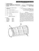
[0008] FIG. 1 is an illustrative view of the top side of wristband invention.
[0009] FIG. 2 is an illustrative view of the bottom side of wristband invention.
[0010] FIG. 3 is an illustrative view of the Programmable LED Strip.
[0011] FIG. 4 is an illustrative view of the wireless controller.
[0012] FIG. 5 is an illustrative view of the microcontroller.
[0013] FIG. 6 is an illustrative view of the Battery power supply.
[0014] FIG. 7 is an illustrative view of the LED Matrix.
[0015] FIG. 8 is an illustrative of a circuit assembly of the wireless wristband apparatus according to an embodiment of the present invention.
[0016] FIG. 9 is an illustrative view of the communication process according to an embodiment of the present invention.
DETAILED DESCRIPTION OF THE PREFERRED EMBODIMENT
[0017] The following discussion describes in detail an embodiment of the wireless play wristband apparatus. This discussion should not be construed, however, as limiting the invention to this particular embodiment.
[0018] FIG. 1A is an illustrative view of top view of the wristband invention first LED of the LED Matrix. FIG. 1B illustrates the wristband, which is made of elastic, or adjustable material. The LED Matrix is covered by a clear, see-through plastic window. There is also a
slot to slide the plays between the LED Matrix and the clear plastic window. The player will be able to see the LED light next to the corresponding play (FIG. 1C) through the clear plastic window on the top of the wristband.
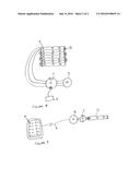
[0019] FIG. 2B is an illustrative view of the bottom view of the wristband invention. FIG. 2A illustrates the velcro enclosure that will house the electronic components for wireless communication and LED control.
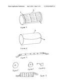
[0020] FIG. 3 is an illustrative view of a programmable LED strip. Several LED Strips can be wired together to create a Matrix, or an LED Matrix can be used (FIG. 7).
[0021] FIG. 4 is an illustrative view of a Bluetooth UART wireless controller. This device will accept the Bluetooth pairing for remote wireless connectivity from a cell phone, or tablet (or any Bluetooth paired device). The Bluetooth UART controller is wired to the microcontroller.
[0022] A Radio Frequency (RF), or XBEE, or Infrared (IR) device may also be used for wireless connectivity.
[0023] While certain novel features of this invention have been described in the Detailed Descriptions above, it is not intended to be limited to said details, since it will be understood that various omissions, changes, and substitutions in the forms of details of the device illustrated and in its operation can be made by those skilled in the art without departing in any way from the spirit of the wristband invention.
[0024] FIG. 5 is an illustrative of view of a microcontroller. This microcontroller contains the programming allowing the wireless controller (Bluetooth, RF, IR, XBEE) to connect and control the LED Matrix within the wristband.
[0025] FIG. 6 is an illustrative of the Battery power source. This power source is typically a 3.3V or 5V power source. It is rechargeable via USB connection to a PC or other USB power source.
[0026] FIG. 8 is an illustrative view of the circuit assembly. FIG. 8A illustrates the LED 1 on the LED strip. FIG. 8B illustrates the wiring between each LED strip (an LED Matrix may also be used). Three wires connect each LED strip and eventually connect to the microcontroller (FIG. 8C), then the microcontroller is wired to the wireless controller (Bluetooth, RF, XBEE, or IR, FIG. 8D).
[0027] FIG. 9 is an illustrative view of the communication process. FIG. 9A illustrates button 1 on the remote wireless device (cell phone, RF, XBEE, IR transmitter). The wireless device (FIG. 9B) pairs with the wireless controller on the wristband, then passes signal through to the microcontroller (FIG. 9C), which sends a signal to the LED 1 on the LED Matrix (or programmable LED strip, FIG. 9D). Therefore, LED 1 is lit when the button 1 is pressed on the wireless device via the communication process illustrated in FIG. 9A. Hence, when button 2 is pressed on the wireless device LED 2 is lit on the wireless wristband.
User Contributions:
Comment about this patent or add new information about this topic:
Images included with this patent application:
 |  |
 |
| Similar patent applications: | |
| Date | Title |
|---|---|
| 2016-06-09 | Wireless communication usb dongle |
| 2016-06-16 | Wireless metrology communication |
| 2016-06-02 | Wireless communication device |
| 2016-06-30 | Intraoral sensing and communications appliance |
| 2018-01-25 | Doorbell communication systems and methods |
| New patent applications in this class: | |
| Date | Title |
|---|---|
| 2016-05-19 | Method and apparatus for visually and audibly indicating the setup and maintenance of a system |
| 2016-05-05 | Backlight indicator for reflective display screens |
| 2016-03-24 | Systems and methods for providing qualitative indication of vibration severity while recording |
| 2016-02-18 | Mounting bracket including emergency lighting |
| 2016-02-18 | Guidance indicator and system for providing egress assistance |
| Top Inventors for class "Communications: electrical" | |
| Rank | Inventor's name |
|---|---|
| 1 | Lowell L. Wood, Jr. |
| 2 | Roderick A. Hyde |
| 3 | Juan Manuel Cruz-Hernandez |
| 4 | John R. Tuttle |
| 5 | Jordin T. Kare |