Patent application title: HEAD-UP DISPLAY AND VEHICLE USING THE SAME
Inventors:
Stefan Graf (Taipei, TW)
Matthias Doepp (Taipei, TW)
Assignees:
MAGNA ELECTRONICS SOLUTIONS GMBH
IPC8 Class: AG02B2701FI
USPC Class:
359630
Class name: Single channel simultaneously to or from plural channels (e.g., light dividing, combining, or plural image forming, etc.) by partial reflection at beam splitting or combining surface superimposing visual information on observer`s field of view (e.g., head-up arrangement, etc.)
Publication date: 2016-05-19
Patent application number: 20160139409
Abstract:
A head-up display (HUD) comprises a detection unit, a picture generating
unit and a control unit. The detection unit detects a position of an
object and generates a detection signal indicated the position of the
object. The picture generating unit comprises a screen and an optical
unit. The screen displays a visual image. The optical unit projects the
visual image onto the screen. The control unit is coupled to the
detection unit and the picture generating unit, controlling the screen to
facing toward the object in response to the detection signal.Claims:
1. A head-up display (HUD), comprising: a detection unit for detecting a
position of an object and generating a detection signal that indicates
the position of the object, the object comprising at least a portion of a
head of a person within a vehicle; a picture generating unit comprising:
a screen configured to be spaced from a vehicle windshield for displaying
a visual image so that the displayed visual image on the screen is
viewable by the person within the vehicle; and an optical unit coupled to
the screen, the optical unit projecting the visual image onto the screen;
and a control unit coupled to the detection unit and the picture
generating unit, the control unit, responsive to the detection signal,
controlling a position of the screen relative to the vehicle windshield
to adjust the screen so that the screen is facing generally toward the
object to enhance viewing of the displayed visual image at the screen by
the person within the vehicle.
2. The HUD of claim 1, wherein the control unit performs face recognition to determine the position of the object relative to the HUD.
3. The HUD of claim 1, wherein the optical unit comprises: a projector for projecting the visual image; and a reflector for guiding the visual image from the projector to the screen.
4. The HUD according to claim 3, wherein the control unit rotates the picture generating unit around a fulcrum, and the fulcrum is located along a line between the center of the screen and the center of the visual image.
5. The HUD of claim 1, wherein the control unit rotates the body of the HUD to control the screen facing towards the object.
6. The HUD of claim 1, wherein the coverage of a detection area of the detection unit covers a driver's position.
7. The HUD of claim 1, wherein the detection unit is installed in a base of the HUD.
8. The HUD of claim 1, wherein the detection unit is installed in a border of the screen.
9. A vehicle applying a head-up display (HUD), wherein the HUD comprises: a detection unit for detecting a position of an object and generating a detection signal that indicates the position of the object, the object comprising at least a portion of a head of a person within the vehicle; a picture generating unit comprising: a screen spaced from a windshield of the vehicle for displaying a visual image so that the displayed visual image on the screen is viewable by the person within the vehicle; and an optical unit coupled to the screen, the optical unit projecting the visual image onto the screen; and a control unit coupled to the detection unit and the picture generating unit, the control unit, responsive to the detection signal, controlling a position of the screen relative to the vehicle windshield to adjust the screen facing generally toward the object to enhance viewing of the displayed visual image at the screen by the person within the vehicle.
10. The vehicle of claim 9, wherein the control unit performs face recognition to determine the position of the object relative to the HUD.
11. The vehicle of claim 9, wherein the optical unit comprises: a projector for projecting the visual image; and a reflector for guiding the visual image from the projector to the screen.
12. The vehicle according to claim 11, wherein the control unit rotates the picture generating unit around a fulcrum, and the fulcrum is located along a line between the center of the screen and the center of the visual image.
13. The vehicle of claim 9, wherein the control unit rotates the body of the HUD to control the screen facing towards the object.
14. The vehicle of claim 9, wherein the coverage of a detection area of the detection unit covers a driver's position.
15. The vehicle of claim 9, wherein the detection unit is installed in a base of the HUD.
16. The vehicle of claim 9, wherein the detection unit is installed in a border of the screen.
Description:
TECHNICAL FIELD
[0001] The disclosure relates in general to an optical display device and a vehicle using the same, and in particular to a head-up display (HUD) and a vehicle using the same.
BACKGROUND
[0002] Today, head-up displays (HUDs) are commonly used in vehicles. Current HUDs can be categorized into two groups: windscreen HUD and combiner HUD. The former uses the windscreen of vehicle as a projection surface, while the later uses an additional combiner screen as the projection surface. The combiner screen HUDs are superior to the windscreen HUDs in means of over-all costs, and in addition, the combiner HUDs can be easily sold as aftermarket products in a one-box design.
[0003] However, the combiner HUD has the particular drawback of their smaller screen size of the projection surface. This may lead to a smaller text and symbol size or less information to be displayed on the combiner screens. Furthermore, the display of the combiner HUD usually cannot use its total surface for the projection because it must compensate for movements of the driver's head.
SUMMARY
[0004] The disclosure is directed to a head-up display (HUD) and a vehicle using the same, which are capable of increasing the usable area of the projection screen of the HUD.
[0005] According to one embodiment, a HUD is provided. The HUD comprises a detection unit, a picture generating unit and a control unit. The detection unit detects a position of an object and generates a detection signal indicated the position of the object. The picture generating unit comprises a screen and an optical unit. The screen displays a visual image. The optical unit projects the visual image onto the screen. The control unit is coupled to the detection unit and the picture generating unit, controlling the screen to facing toward the object in response to the detection signal.
[0006] According to another embodiment, a vehicle applying a HUD is provided. The HUD comprises a detection unit, a picture generating unit and a control unit. The detection unit detects a position of an object and generates a detection signal indicated the position of the object. The picture generating unit comprises a screen and an optical unit. The screen displays a visual image. The optical unit projects the visual image onto the screen. The control unit is coupled to the detection unit and the picture generating unit, controlling the screen to facing toward the object in response to the detection signal.
BRIEF DESCRIPTION OF THE DRAWINGS
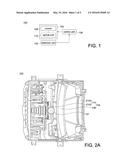
[0007] FIG. 1 shows a block diagram of a head-up display (HUD) according to an embodiment of the present disclosure.
[0008] FIG. 2A shows a top view of a picture generating unit of a HUD according to an embodiment of the present disclosure.
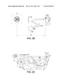
[0009] FIG. 2B shows a schematic diagram of the configuration of the picture generating unit according to an embodiment of the present disclosure.
[0010] FIG. 2C shows the potential location for disposing the fulcrum of the HUD.
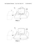
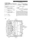
[0011] FIG. 3 shows a schematic diagram of a HUD according to an embodiment of the present disclosure.
[0012] FIG. 4 shows a schematic diagram of a HUD according to an embodiment of the present disclosure.
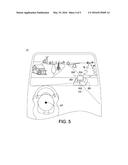
[0013] FIG. 5 shows a schematic diagram of a vehicle installing a HUD.
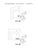
[0014] FIG. 6A shows an exemplary picture displayed on a screen of a HUD in a view from a driver's position.
[0015] FIG. 6B shows an exemplary picture displayed on a screen of a HUD in a view from a driver's position.
[0016] In the following detailed description, for purposes of explanation, numerous specific details are set forth in order to provide a thorough understanding of the disclosed embodiments. It will be apparent, however, that one or more embodiments may be practiced without these specific details. In other instances, well-known structures and devices are schematically shown in order to simplify the drawing.
DETAILED DESCRIPTION
[0017] Below, exemplary embodiments will be described in detail with reference to accompanying drawings so as to be easily realized by a person having ordinary knowledge in the art. The inventive concept may be embodied in various forms without being limited to the exemplary embodiments set forth herein. Descriptions of well-known parts are omitted for clarity, and like reference numerals refer to like elements throughout.
[0018] FIG. 1 shows a block diagram of a head-up display (HUD) 100 according to an embodiment of the present disclosure. The HUD 100 comprises a detection unit 102, a picture generating unit 104 and a control unit 106.
[0019] The detection unit 102 is configured to detect an object and generate a detection signal which indicated the position of the object relative to the HUD 100. For example, the detection unit 102 may detect the driver's head/face in the vehicle from the perspective of the HUD 100 and generate a detection signal which indicated the position of the driver relative to the HUD 100 accordingly. The detection unit 102 can realized by a camera, an ultrasonic sensor, a radar, an infra-red (IR) based sensor or any other sensors can be used for performing such detection. The detection signal may be, for example, a digital representation of the detected object. The position of the driver's head/face relative to the HUD 102 can be identified and processed by the control unit 106 based on the detection signal. Details of the operation of the control unit 106 are further exemplified and described in the following detailed description.
[0020] The picture generating unit 104 comprises a screen 108 and an optical unit 110. The screen 108 is configured to display a visual image. The optical unit 110 is coupled to the screen 108 and configured to project the visual image onto the screen 108. In one embodiment, the visual image may include driving-relevant information such as navigation map, vehicle speed, the amount of remaining oil, over speed warning and etc. Thus, the driver can keep his/her eyes on the road while checking on the driving-relevant information provided by the HUD 100 thereby ensuring the safety and security.
[0021] The control unit 106 is coupled to the detection unit 102 and the picture generating unit 104, controlling the screen 108 to facing toward the object in response to the detection signal. In one embodiment, the control unit 106 is configured to control an angle of inclination and/or rotation of the picture generating unit 104 in response to the detection signal. For example, in response to the detection signal generated by the detection unit 102, the control unit 106 may control the angle of inclination and/or rotation of the picture generating unit 104 to adjust the screen 108 to face towards the object.
[0022] The angle of inclination and/or rotation of the picture generating unit 104 controlled by the control unit 106 can be determined by the position of the object. For example, after the detection unit 102 detects an object (e.g., the driver's head/face), the control unit 106 may determine the position of the object relative to the HUD 100 by such as performing face recognition and then control the angle of inclination and/or rotation of the picture generating unit 104 to adjust the screen 108 to face towards the position of the object. Accordingly, even the driver changes his/her position while driving, the movement of the driver can be compensated by adjusting the screen 108 to face towards the driver's head/face, and thus the usable area of the screen 108 of the HUD 100 can be increased.
[0023] Referring to FIG. 2A and FIG. 2B, FIG. 2A shows an exemplary top view of the HUD 100 according to an embodiment of the present disclosure, and FIG. 2B shows a schematic diagram of the configuration of the picture generating unit 104 of the HUD 100. In the embodiment, the optical unit 110 of the HUD 100 comprises a projector 2102 and a reflector 2104.
[0024] The projector 2102 is configured to project the visual image. In one embodiment, the projector 2102 can be a TFT display or other kinds of picture projecting source. The reflector 2104 is configured to guide the visual image from the projector 2102 to the screen 108 and thus the visual image can be projected onto the screen 108. In one embodiment, the reflector 2104 can be a mirror.
[0025] As shown in FIG. 2B, light projected by the projector 2102 is guided to the screen 108 through the reflector 2104 so that the driver can see the virtual image VI through the screen 108. In one embodiment, the distance (DL) between the driver and the virtual image VI is 190 mm. In one embodiment, the virtual image VI measures by 130 mm×40 mm.
[0026] Referring to FIG. 2A again, in one embodiment, the picture generating unit 104 can be controlled by the control unit 106 to rotate around a vertical axis. As shown in FIG. 2A, the HUD 100 further comprises a fulcrum (FP) used for rotating the picture generating unit 104 horizontally.
[0027] FIG. 2C shows the potential location for disposing the fulcrum (FP) of the HUD 100. In FIG. 2C, the box EA represents the position of the driver's eyes. The driver may see the virtual image VI through the screen 108. In the embodiment, the fulcrum (FP) is located along a line between the center of the screen 108 and the center of the visual image VI. However, the present disclosure is not limited thereto. The fulcrum (FP) can also be disposed at other positions of the HUD 100 according to various designs.
[0028] FIG. 3 shows a schematic diagram of a HUD 300 according to an embodiment of the present disclosure. In the example of FIG. 3, the picture generating unit 304 is a movable part of the HUD 300 and can be rotated in at least two directions (a vertical direction and a horizontal direction). For example, in response to a detection signal generated by the detection unit 302, the control unit (not shown in FIG. 3) of the HUD 300 may control an angle of inclination and/or rotation of the picture generating unit 304 to adjust the screen 306 of the HUD 300 to face towards the object 31 (e.g., the driver's head/face).
[0029] FIG. 4 shows a schematic diagram of a HUD 400 according to an embodiment of the present disclosure. In the example of FIG. 4, the detection unit 402 captures a picture of an object 41 (e.g., the driver's head/face) and generates a detection signal accordingly. In response to the detection signal of the detection unit 402, the control unit (not shown in FIG. 4) of the HUD 400 may rotate the whole body of the HUD 400 so as to control the screen 406 of the HUD 400 facing towards the object 41. In other words, compared to the embodiment shown in FIG. 3, the HUD 400 of the embodiment shown in FIG. 4 can be rotated horizontally in response to the detection signal so that the screen 406 of the HUD 400 can maintain facing towards the object 41 even though the object 41 changes its position.
[0030] FIG. 5 shows a schematic diagram of a vehicle 51 applying a HUD 500. In the example of FIG. 5, the coverage of a detection area (DA) of the detection unit 502 covers a driver's position (DP). The detection unit 502 may detect the driver's head/face and then generate a detection signal. In response to the detection signal generated by the detection unit 502, the control unit (not shown in FIG. 5) of the HUD 500 may determine the driver's position (DP) relative to the HUD 500 by such as performing face recognition.
[0031] The detection unit 502 of the HUD 500 can be located at any position inside the vehicle 51 from which it can detect the position of the driver's eyes. In one embodiment, the detection unit 502 is installed in a position that allows the coverage of the detection area (DA) to cover the driver's position (DP) in the vehicle 51. As shown in FIG. 5, the detection unit 502 is installed in the base (BS) of the HUD 500 that faces towards the driver. In another example, the detection unit 502 can be installed at the border (BD) of the screen 504 of the HUD 500 (if existing) as long as the detection unit 502 can detect the position of the driver's eyes.
[0032] FIG. 6A shows an exemplary picture displayed on a screen 604 of a HUD 600 in a view from a driver's position (DP'). In the example of FIG. 6A, some navigation information can not be seen by the driver when the screen 604 does not face towards the driver because the viewable area of screen 604 is limited by the viewing angle of the driver.
[0033] When the HUD 600 finds that the screen 604 does not face towards the driver, the HUD 600 may perform the above mentioned adjustment operations to adjust the screen 604 to face towards the driver. After the screen 604 is adjusted to face towards the driver, the viewable area of screen 604 is maximized and the loss of navigation information is avoided, as shown in FIG. 6B.
[0034] According to the above, the HUD of the present disclosure may control its screen facing towards the driver. Accordingly, part of the area of screen reserved for compensating the movement of the driver can be reduced or omitted, and thus the usable area of the screen of the HUD can be increased.
[0035] It will be apparent to those skilled in the art that various modifications and variations can be made to the disclosed embodiments. It is intended that the specification and examples be considered as exemplary only, with a true scope of the disclosure being indicated by the following claims and their equivalents.
User Contributions:
Comment about this patent or add new information about this topic:
Images included with this patent application:
 |  |
 |  |
 |  |
| Similar patent applications: | |
| Date | Title |
|---|---|
| 2016-04-07 | Transparent display apparatus and method for controlling the same |
| 2016-05-19 | Head-up display device and backlight device |
| 2015-11-19 | Lens and method of producing the same |
| 2016-03-24 | Laser beam splitting and angle adjusting device |
| 2015-10-15 | Electrofluidic display and methods for making |
| New patent applications in this class: | |
| Date | Title |
|---|---|
| 2022-05-05 | Virtual image display device and optical unit |
| 2022-05-05 | Phase structure on surface-relief grating-based waveguide display |
| 2022-05-05 | Virtual image display device and optical unit |
| 2019-05-16 | Light directing filters |
| 2018-01-25 | Image display device and program |
| New patent applications from these inventors: | |
| Date | Title |
|---|---|
| 2016-05-26 | Automotive lighting device and a vehicle having the same |
| Top Inventors for class "Optical: systems and elements" | |
| Rank | Inventor's name |
|---|---|
| 1 | Tsung Han Tsai |
| 2 | Hsin Hsuan Huang |
| 3 | Michio Cho |
| 4 | Niall R. Lynam |
| 5 | Tsung-Han Tsai |