Patent application title: Sport Equipment Container
Inventors:
Jose L Garcia, Jr. (Clovis, NM, US)
IPC8 Class: AA63B7100FI
USPC Class:
2063151
Class name: Special receptacle or package for a sport implement, exercise device, or game
Publication date: 2016-04-28
Patent application number: 20160114237
Abstract:
A bucket storage system is disclosed. The bucket storage system
comprising a pail and a sleeve. The pail comprising a base and a
sidewall. The pail contains a bucket cavity configured to store and hold
sports equipment. The pail comprises a bottom diameter and a top
diameter. The bucket cavity comprises a space above the base comprises
and within the sidewall of the pail. The sleeve comprises a sidewall and
a sleeve cavity. The sleeve comprises a upper sleeve diameter and a lower
sleeve diameter. The upper sleeve diameter is greater in size than the
lower sleeve diameter. The upper sleeve diameter is smaller than the top
diameter of the pail.Claims:
1. A bucket storage system, comprising: said bucket storage system
comprising a pail and a sleeve; said pail comprising a base and a
sidewall; said pail contains a bucket cavity configured to store and hold
sports equipment; said pail comprises a bottom diameter and a top
diameter; said bucket cavity comprises a space above said base and within
said sidewall of said pail; said sleeve comprises a sidewall and a sleeve
cavity; said sleeve comprises a upper sleeve diameter and a lower sleeve
diameter; said upper sleeve diameter is smaller than said top diameter of
said pail; a portion of said sleeve is configured to selectively slide
into and out of said pail for storage and use; said bucket storage system
comprises a collapsed configuration and a one or more assembled
configurations; said collapsed configuration comprises said sleeve nested
within said pail; said one or more assembled configurations comprise said
pail upside down with said sleeve stacked on top of said pail; said
bucket storage system further comprising a lid; said lid comprises a lid
threading; said pail further comprises a pail threading; said lid is
configured to selectively attach to said pail by screwing said lid
threading into and out of said pail threading; said lid comprises a lid
height; said pail with said lid attached comprises a variable height
ranging to about the distance equal to said lid height; therefore, said
bucket storage system is configured to have a variable height; said
sleeve selectively locks into said pail with a threading; said threading
comprising a lip threading and a sleeve threading; wherein said lip
threading selectively slides into said sleeve threading; said sleeve
further comprises a one or more handles; and said handles comprise holes
in said sidewall of said sleeve.
2. A bucket storage system, comprising: said bucket storage system comprising a pail and a sleeve; said pail comprising a base and a sidewall; said pail contains a bucket cavity configured to store and hold sports equipment; said pail comprises a bottom diameter and a top diameter; said bucket cavity comprises a space above said base and within said sidewall of said pail; said sleeve comprises a sidewall and a sleeve cavity; said sleeve comprises a upper sleeve diameter and a lower sleeve diameter; said upper sleeve diameter is smaller than said top diameter of said pail; a portion of said sleeve is configured to selectively slide into and out of said pail for storage and use; said bucket storage system comprises a collapsed configuration and a one or more assembled configurations; said collapsed configuration comprises said sleeve nested within said pail; and said one or more assembled configurations comprise said pail upside down with said sleeve stacked on top of said pail.
3. The bucket storage system of claim 2, comprising: said bucket storage system further comprising a lid; said lid comprises a lid threading; said pail further comprises a pail threading; said lid is configured to selectively attach to said pail by screwing said lid threading into and out of said pail threading; said lid comprises a lid height; said pail with said lid attached comprises a variable height ranging to about the distance equal to said lid height; and therefore, said bucket storage system is configured to have a variable height.
4. The bucket storage system of claim 3, comprising: said sleeve selectively locks into said pail with a threading; said threading comprising a lip threading and a sleeve threading; and wherein said lip threading slides into said sleeve threading.
5. The bucket storage system of claim 3, comprising: said sleeve further comprises a one or more handles; and said handles comprise holes in said sidewall of said sleeve.
6. The bucket storage system of claim 2, comprising: said pail and said sleeve comprise a conical shape with a larger upper diameter than lower diameter.
7. The bucket storage system of claim 2, comprising: said base of said pail comprises a non-slip surface configured to resist movement between said pail and said sleeve with said bucket storage system in said one or more assembled configurations.
8. The bucket storage system of claim 2, comprising: said pail and said sleeve comprise a substantially rectangular cross-section.
9. The bucket storage system of claim 2, comprising: said pail and said sleeve comprise a substantially circular cross-section.
10. A bucket storage method, comprising: removing said lid from said pail, replacing said lid if necessary for transport or storage, removing said lid if reattached to said pail, removing said one or more ball from said bucket cavity, attaching said lid to said pail, inverting said pail, fitting said sleeve on said pail, and and placing said one or more ball in said sleeve cavity; wherein, said bucket storage system comprising a pail and a sleeve; said pail comprising a base and a sidewall; said pail contains a bucket cavity configured to store and hold sports equipment; said pail comprises a bottom diameter and a top diameter; said bucket cavity comprises a space above said base and within said sidewall of said pail; said sleeve comprises a sidewall and a sleeve cavity; said sleeve comprises a upper sleeve diameter and a lower sleeve diameter; said upper sleeve diameter is smaller than said top diameter of said pail; a portion of said sleeve is configured to selectively slide into and out of said pail for storage and use; said bucket storage system comprises a collapsed configuration and a one or more assembled configurations; said collapsed configuration comprises said sleeve nested within said pail; and said one or more assembled configurations comprise said pail upside down with said sleeve stacked on top of said pail.
Description:
CROSS-REFERENCE TO RELATED APPLICATIONS
[0001] This application claims benefit to U.S. Patent Application No. 62/069,379, filed on 2014 Oct. 28, which is hereby incorporated by reference.
STATEMENT REGARDING FEDERALLY SPONSORED RESEARCH OR DEVELOPMENT (IF APPLICABLE)
[0002] Not applicable.
REFERENCE TO SEQUENCE LISTING, A TABLE, OR A COMPUTER PROGRAM LISTING COMPACT DISC APPENDIX (IF APPLICABLE)
[0003] Not applicable.
BACKGROUND OF THE INVENTION
[0004] This disclosure relates generally to a Sport Equipment Container. Examples of similar disclosures can be found at U.S. Pat. No. 4,671,406, U.S. Pat. No. 6,213,574, U.S. Pat. No. 7,293,748, US2008/00268879, US2011/0262259, US2012/0298537, and D478808. However, none of the known inventions and patents, taken either singularly or in combination, is seen to describe the instant disclosure as claimed. Accordingly, said Sport Equipment Container would be advantageous.
BRIEF SUMMARY OF THE INVENTION
[0005] A bucket storage system is disclosed. Said bucket storage system comprising a pail and a sleeve. Said pail comprising a base and a sidewall. Said pail contains a bucket cavity configured to store and hold sports equipment. Said pail comprises a bottom diameter and a top diameter. Said bucket cavity comprises a space above said base comprises and within said sidewall of said pail. Said sleeve comprises a sidewall and a sleeve cavity. Said sleeve comprises a upper sleeve diameter and a lower sleeve diameter. Said upper sleeve diameter is greater in size than said lower sleeve diameter. Said upper sleeve diameter is smaller than said top diameter of said pail;
[0006] a portion of said sleeve is configured to selectively slide into and out of said pail for storage and use. Said bucket storage system comprises a collapsed configuration and a one or more assembled configurations. Said collapsed configuration comprises said sleeve nested within said pail; and. Said one or more assembled configurations comprise said pail upside down with said sleeve stacked on top of said pail.
[0007] A bucket storage method, comprising: removing said lid from said pail, replacing said lid if necessary for transport or storage, removing said lid if reattached to said pail, removing said one or more ball from said bucket cavity, attaching said lid to said pail, inverting said pail, fitting said sleeve on said pail, and placing said one or more ball in said sleeve cavity; wherein. Said bucket storage system comprising a pail and a sleeve. Said pail comprising a base and a sidewall. Said pail contains a bucket cavity configured to store and hold sports equipment. Said pail comprises a bottom diameter and a top diameter. Said bucket cavity comprises a space above said base comprises and within said sidewall of said pail. Said sleeve comprises a sidewall and a sleeve cavity. Said sleeve comprises a upper sleeve diameter and a lower sleeve diameter. Said upper sleeve diameter is greater in size than said lower sleeve diameter. Said upper sleeve diameter is smaller than said top diameter of said pail. A portion of said sleeve is configured to selectively slide into and out of said pail for storage and use. Said bucket storage system comprises a collapsed configuration and a one or more assembled configurations. Said collapsed configuration comprises said sleeve nested within said pail; and. Said one or more assembled configurations comprise said pail upside down with said sleeve stacked on top of said pail.
BRIEF DESCRIPTION OF THE SEVERAL VIEWS OF THE DRAWING
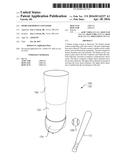
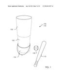
[0008] FIG. 1 illustrates a perspective overview of a bucket storage system 100 in a collapsed configuration 120 with a ball 108 and a sporting equipment 110.
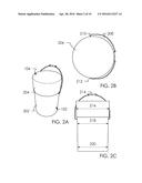
[0009] FIGS. 2A, 2B, and 2C illustrate a perspective overview of said pail 102 with said lid 104, an elevated top view of said lid 104, and a side view of said pail 102 with said lid 104.
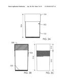
[0010] FIGS. 3A, 3B, and 3C illustrate a cross-section side view of said pail 102 with said lid 104 in a closed position, a cross-section side view of said pail 102 with said lid 104 in an expanded position, and an elevated side view of said pail 102 and said lid 104 in an expanded position.
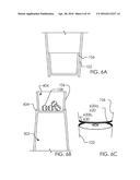
[0011] FIGS. 4A and 4B illustrate a perspective overview and an elevated overview of said sleeve 106 and a top-down view of said sleeve 106.
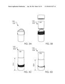
[0012] FIGS. 5A, 5B, 5C and 5D illustrate a perspective overview of said bucket storage system 100 in said collapsed configuration 120, an exploded view 502, a first assembled configuration 504, and a second assembled configuration 506.
[0013] FIGS. 6A and 6B illustrate a cross-section side view of a storable sleeve 602 stored inside said pail 102 and a cross-section side view of said storable sleeve 602 mounted internally within a lip 604 of said pail 102. FIG. 6C illustrates said bucket storage system 100 with a threading lock between said pail 102 and said storable sleeve 602.
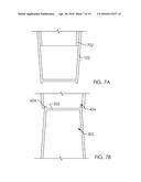
[0014] FIGS. 7A and 7B illustrate a cross-section side view of a storable sleeve 702 stored inside said pail 102 and a cross-section side view of said storable sleeve 702 mounted externally of said lip 604 of said pail 102.
[0015] FIGS. 8A and 8B illustrate a side view of said bucket storage system 100 and a cross-section side view of said bucket storage system 100 containing a one or more said ball 108.
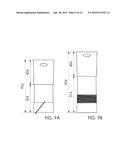
[0016] FIGS. 9A and 9B illustrate a side view of said bucket storage system 100 in a lowest height configuration 902 and a side view of said bucket storage system 100 in a maximum height configuration 904.
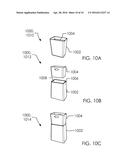
[0017] FIGS. 10A, 10B and 10C illustrate a bucket storage system 1000 in a collapsed configuration 1010, an exploded configuration 1012, and an assembled configuration 1014.
DETAILED DESCRIPTION OF THE INVENTION
[0018] Described herein is a sport equipment container. The following description is presented to enable any person skilled in the art to make and use the invention as claimed and is provided in the context of the particular examples discussed below, variations of which will be readily apparent to those skilled in the art. In the interest of clarity, not all features of an actual implementation are described in this specification. It will be appreciated that in the development of any such actual implementation (as in any development project), design decisions must be made to achieve the designers' specific goals (e.g., compliance with system- and business-related constraints), and that these goals will vary from one implementation to another. It will also be appreciated that such development effort might be complex and time-consuming, but would nevertheless be a routine undertaking for those of ordinary skill in the field of the appropriate art having the benefit of this disclosure. Accordingly, the claims appended hereto are not intended to be limited by the disclosed embodiments, but are to be accorded their widest scope consistent with the principles and features disclosed herein.
[0019] FIG. 1 illustrates a perspective overview of a bucket storage system 100 in a collapsed configuration 120 with a ball 108 and a sporting equipment 110.
[0020] In one embodiment, said bucket storage system 100 can comprise components including but not limited to a pail 102, a lid 104, and a sleeve 106. In one embodiment, said bucket storage system 100 can provide ease of access to users in storing sporting goods such as said ball 108 and said sporting equipment 110. For instance, said bucket storage system 100 can provide both storage within said pail 102 but can also provide elevated storage within said sleeve 106 (not illustrated here, see below). Elevated storage within said sleeve 106 would enable a user of said bucket storage system 100 to access items in an upright standing position without crouching or bending over. In one embodiment, said lid 104 and said sleeve 106 can be adjusted in relation to said pail 102 to reduce the size of and provide easier transportation of said bucket storage system 100.
[0021] FIGS. 2A, 2B, and 2C illustrate a perspective overview of said pail 102 with said lid 104, an elevated top view of said lid 104, and a side view of said pail 102 with said lid 104.
[0022] In one embodiment, said pail 102 can comprise a sidewall 202 and a handle 208 with a grip 214. Said lid 104 can comprise a sidewall 204. In one embodiment, said sidewall 202 and said sidewall 204 can be a substantially cylindrical shape, as illustrated. In one embodiment, said bucket storage system 100 can be made of plastics, metal, or wood.
[0023] In one embodiment, said handle 208 can attach to said bucket storage system 100 at opposing sides of said sidewall 202 with a handle anchor 210 and a handle anchor 212.
[0024] In one embodiment, said lid 104 can comprise a top surface 206 and said sidewall 204. In one embodiment, said top surface 206 can comprise a similar material to said sidewall 204 or a textured or different material to provide a non-slip surface when said top surface 206 is placed against another surface. In one embodiment, said handle 208 attaches to said sidewall 204 on said lid 104 (not illustrated here as attached to said lid).
[0025] In one embodiment, said pail 102 can have varying diameters while said lid 104 can have a single diameter. Meaning said lid 104 can comprise a true cylindrical shape and said pail 102 can be more conical. For instance, said pail 102 can have a top diameter 218 and a bottom diameter 220 where said top diameter 218 is larger than said bottom diameter 220. On the other hand, said lid 104 can have a lid diameter 216 wherein said lid diameter 216 is larger than said top diameter 218.
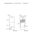
[0026] FIGS. 3A, 3B, and 3C illustrate a cross-section side view of said pail 102 with said lid 104 in a closed position, a cross-section side view of said pail 102 with said lid 104 in an expanded position, and an elevated side view of said pail 102 and said lid 104 in an expanded position.
[0027] In one embodiment, said lid 104 can be removeably attached to said pail 102. Furthermore, a bucket cavity 302 in the area within said pail 102 and said lid 104 can be expanded or compacted depending on the location of said lid 104 in relation to said pail 102. For instance, said pail 102 and said lid 104 can have a compacted height 304 when said lid 104 is fully attached to said pail 102. In one embodiment, said lid 104 has lid threading 308 that is complementary to said pail threading 306 on said pail 102. Specifically, said lid 104 can be rotateably adjusted in relation to said pail 102 to adjust the vertical position of said lid 104. In one embodiment, said pail 102 can have a pail height 310 while said lid 104 can have a lid height 312 thus having an expanded height 314. In one embodiment, said lid 104 can be adjusted on said pail 102 to have a height between said compacted height 304 and said expanded height 314.
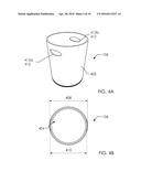
[0028] FIGS. 4A and 4B illustrate a perspective overview and an elevated overview of said sleeve 106 and a top-down view of said sleeve 106.
[0029] In one embodiment, said sleeve 106 can have a sidewall 402. In one embodiment, said sidewall 402 can be cylindrical and comprise of plastics, metal, or wood. In one embodiment, said sleeve 106 can have a sleeve height 406. Additionally, said sleeve 106 can have an upper sleeve diameter 408 and a lower sleeve diameter 410. As a result, said sleeve 106 can taper from top to bottom. In one embodiment, said sleeve 106 can have a sleeve cavity 404 in the aperture space between said sidewall 402.
[0030] In one embodiment, said sleeve 106 can comprise a one or more handles 412 (which can comprise a first handle 412a and a second handle 412b), as illustrated. Said one or more handles 412 can be used to remove said sleeve 106 from said pail 102 when nested within said pail 102.
[0031] FIGS. 5A, 5B, 5C and 5D illustrate a perspective overview of said bucket storage system 100 in said collapsed configuration 120, an exploded view 502, a first assembled configuration 504, and a second assembled configuration 506.
[0032] In one embodiment, said sleeve 106 can be placed and removed with no tools. In one embodiment, said sleeve 106 can stay attached to said pail 102 via friction between said sleeve 106 and said pail 102. When said sleeve 106 is attached to said pail 102, a base 320 separates said bucket cavity 302 and said sleeve cavity 404. Essentially, said base 320 provides a separation of storage in said bucket storage system 100 and elevated storage in said sleeve cavity 404.
[0033] In one embodiment, said bucket storage system 100 can comprise a one or more assembled configuration which can comprise said first assembled configuration 504 and said second assembled configuration 506.
[0034] FIGS. 6A and 6B illustrate a cross-section side view of a storable sleeve 602 stored inside said pail 102 and a cross-section side view of said storable sleeve 602 mounted internally within a lip 604 of said pail 102. FIG. 6C illustrates said bucket storage system 100 with a threading lock between said pail 102 and said storable sleeve 602.
[0035] In one embodiment, said storable sleeve 602 can be stored within said pail 102 during transport or when bucket storage system 100 is not in use. In one embodiment, said bucket storage system 100 can be setup by removing said storable sleeve 602 from said pail 102, inverting said pail 102, and fitting said storable sleeve 602 within said lip 604. In one embodiment, said base 320 serves as a separation between said bucket cavity 302 and said sleeve cavity 404. As a result, said sleeve cavity 404 can be elevated and provide ease of access to items placed within said sleeve cavity 404.
[0036] In one embodiment, said pail 102 can lock into said lip 604 of said pail 102 with a threading 620. In one embodiment, said threading 620 can comprise a sleeve threading 620a and a lip threading 620b.
[0037] FIGS. 7A and 7B illustrate a cross-section side view of a storable sleeve 702 stored inside said pail 102 and a cross-section side view of said storable sleeve 702 mounted externally of said lip 604 of said pail 102.
[0038] In one embodiment, said storable sleeve 702 can be stored within said pail 102 during transport or when bucket storage system 100 is not in use. In one embodiment, said bucket storage system 100 can be setup by removing said storable sleeve 702 from said pail 102, inverting said pail 102, and fitting said storable sleeve 702 around said lip 604. In one embodiment, said base 320 serves as a separation between said bucket cavity 302 and said sleeve cavity 404. As a result, said sleeve cavity 404 can be elevated and provide ease of access to items placed within said sleeve cavity 404.
[0039] FIGS. 8A and 8B illustrate a side view of said bucket storage system 100 and a cross-section side view of said bucket storage system 100 containing a one or more said ball 108.
[0040] In one embodiment, said bucket storage system 100 can be set up as follows: removing said lid 104 from said pail 102, placing said one or more ball 108 in said bucket cavity 302, replacing said lid 104 if necessary for transport or storage, removing said lid 104 if reattached to said pail 102, removing said one or more ball 108 from said bucket cavity 302, attaching said lid 104 to said pail 102, inverting said pail 102, fitting said sleeve 106 on said pail 102, and placing said one or more ball 108 in said sleeve cavity 404.
[0041] FIGS. 9A and 9B illustrate a side view of said bucket storage system 100 in a lowest height configuration 902 and a side view of said bucket storage system 100 in a maximum height configuration 904.
[0042] In one embodiment, said lid 104 can be rotateably adjusted on said pail 102 until said lid 104 is fully secured onto said pail 102 having said compacted height 304. In one embodiment, said compacted height 304 and said sleeve height 406 add together to give said lowest height configuration 902. In one embodiment, said lid 104 can be rotateably adjusted on said pail 102 to give said expanded height 314. Said expanded height 314 coupled with said sleeve height 406 can equal said maximum height configuration 904. In one embodiment, said bucket storage system 100 can be adjusted to provide a desired height between said lowest height configuration 902 and said maximum height configuration 904.
[0043] FIGS. 10A, 10B and 10C illustrate a bucket storage system 1000 in a collapsed configuration 1010, an exploded configuration 1012, and an assembled configuration 1014.
[0044] In one embodiment, said bucket storage system 1000 can comprise a pail 1002, and a sleeve 1004. In one embodiment, said pail 1002 can comprise a bottom rim 1006 and a base 1008. In one embodiment, said bucket storage system 1000 can operate similar to said bucket storage system 100, as illustrated and understood. In one embodiment, said bucket storage system 1000 can comprise a substantially rectangular shape as opposed to circular shape.
[0045] Various changes in the details of the illustrated operational methods are possible without departing from the scope of the following claims. Some embodiments may combine the activities described herein as being separate steps. Similarly, one or more of the described steps may be omitted, depending upon the specific operational environment the method is being implemented in. It is to be understood that the above description is intended to be illustrative, and not restrictive. For example, the above-described embodiments may be used in combination with each other. Many other embodiments will be apparent to those of skill in the art upon reviewing the above description. The scope of the invention should, therefore, be determined with reference to the appended claims, along with the full scope of equivalents to which such claims are entitled. In the appended claims, the terms "including" and "in which" are used as the plain-English equivalents of the respective terms "comprising" and "wherein."
User Contributions:
Comment about this patent or add new information about this topic:
Images included with this patent application:
 |  |
 |  |
 |  |
 |  |
 |  |
 |
| Similar patent applications: | |
| Date | Title |
|---|---|
| 2016-05-05 | Storage method for trifluoroethylene, and storage container for trifluoroethylene |
| 2015-11-26 | Supplemental container tray |
| 2016-01-28 | Portable beverage container |
| 2016-03-17 | Box for reinforcing a shipping container |
| 2016-03-24 | Dispensing cap for beverage container |
| New patent applications in this class: | |
| Date | Title |
|---|---|
| 2017-08-17 | Spur case |
| 2016-12-29 | Sports bag |
| 2016-03-24 | Adjustable carry bag |
| 2016-03-10 | Portable gymnic machine and bag-container for its transport and utilization |
| 2016-02-25 | Golf tee holding unit |
| Top Inventors for class "Special receptacle or package" | |
| Rank | Inventor's name |
|---|---|
| 1 | Donald E. Weder |
| 2 | Brett R. Glass |
| 3 | Daniel Lee Bizzell |
| 4 | Andrea Biondi |
| 5 | Nicole E. Glass |