Patent application title: Tool Press for Shaping Boot of an Ice Skate
Inventors:
Wally Wayne Tatomir (Raleigh, NC, US)
Wally Wayne Tatomir (Raleigh, NC, US)
IPC8 Class: AA43D314FI
USPC Class:
12 535
Class name: Upper machines assembled shoe shaping by conforming press action
Publication date: 2016-04-07
Patent application number: 20160095391
Abstract:
A tool for shaping an ice skate boot includes a ram member and a
corresponding receiver member. The ram member is placed against a
selected area of a first surface of the ice skate boot that causes a user
discomfort, and is pressed against the selected area so as to flatten or
shape the selected area. The receiver member, which includes a cavity and
a rim, is placed against an opposing second surface of the boot. One or
more arcuate notches formed in the rim of the receiver member receive a
part of the second surface of the ice skate boot when the ram member
presses against the first surface of the ice skate boot.Claims:
1. A tool for shaping an ice skate boot, the tool comprising: first and
second opposing arms, each arm comprising a terminal end configured to
move towards and away from each other; a ram coupled to the terminal end
of the first arm, and configured to press against a first surface of an
ice skate boot when the terminal end of the first arm moves towards the
terminal end of the second arm; and a receiver coupled to the terminal
end of the second arm and comprising: a cavity defined by a sidewall
having a rim, wherein the rim is configured to press against a surface of
an ice skate boot when the ram presses against an opposing surface of the
ice skate boot; and one or more arcuate notches formed in the rim, and
configured to receive the surface of the ice skate boot when the ram
presses against the opposing surface of the ice skate boot.
2. The tool of claim 1 wherein the ram and the receiver are each elongated, and wherein the cavity is sized to receive the ram.
3. The tool of claim 2 wherein the one or more arcuate notches comprise a first arcuate notch formed at one end of the elongated receiver, and a second arcuate notch formed at an opposite end of the elongated receiver.
4. The tool of claim 1 wherein the sidewall comprises an interior surface that defines the cavity and an opposing exterior surface, and wherein a portion of the rim overhangs the exterior surface of the sidewall.
5. The tool of claim 4 wherein the receiver further comprises a base extending between a peripheral edge of the exterior surface of the sidewall, and wherein an interior surface of the base forms a floor surface of the cavity.
6. The tool of claim 1 wherein the ram and the receiver each comprise a coupling member configured to releasably couple the ram and the receiver to the terminal ends of the first and second arms, respectively.
7. A tool for shaping an ice skate boot, the tool comprising: a receiver configured to couple to the tool opposite a ram and comprising: a cavity defined by a sidewall having a rim, wherein the rim is configured to press against a surface of an ice skate boot when the ram presses against an opposing surface of the ice skate boot; and one or more arcuate notches formed in the rim to receive the surface of the ice skate boot when the ram presses against the opposing surface of the ice skate boot.
8. The tool of claim 7 wherein the sidewall comprises an interior surface and an opposing exterior surface, and wherein the rim is shaped to overhang the exterior surface of the sidewall.
9. The tool of claim 7 wherein the rim surrounds an opening into the cavity, and wherein the surface of the ice skate boot extends through the opening and into the cavity when the ram presses against the opposing surface of the ice skate boot.
10. The tool of claim 7 wherein the receiver comprises an elongated receiver sized to receive a correspondingly elongated ram.
11. The tool of claim 10 wherein the one or more arcuate notches formed in the rim comprise first and second arcuate notches respectively formed in opposing first and second ends of the rim.
12. The tool of claim 10 wherein the rim comprises a pair of opposing longitudinal contact surfaces that press against the surface of the ice skate boot when the ram presses against the opposing surface of the ice skate boot.
13. The tool of claim 12 wherein the pair of opposing longitudinal contact surfaces extend between the opposing first and second ends of the rim and are substantially flat.
14. The tool of claim 7 wherein the receiver further comprises a base extending between a peripheral edge of an exterior surface of the sidewall such that a surface of the base forms an interior floor surface of the cavity.
15. The tool of claim 14 wherein the receiver further comprises a coupling member extending substantially perpendicularly and away from the base, the coupling member configured to releasably couple the receiver to the tool.
16. A tool for shaping an ice skate boot, the tool comprising: a ram configured to press against a first surface of an ice skate boot; and a receiver disposed opposite the ram and comprising: a cavity defined by a sidewall having a rim; and an arcuate notch formed in the rim, wherein the cavity and the arcuate notch are configured to receive a second surface of the ice skate boot when the ram presses against the first surface of the ice skate boot.
17. The tool of claim 16 wherein the ram comprises an elongated member that is formed to fit within the cavity of the receiver.
18. The tool of claim 16 wherein the sidewall comprises an interior surface that forms the cavity, and an exterior surface, and wherein the rim is formed to overhang the exterior surface.
19. The tool of claim 16 further comprising a base that forms a floor surface of the cavity.
20. A method for shaping an ice skate boot using a boot shaping tool, the method comprising: placing a selected area of a first surface of an ice skate boot against a first member of the boot shaping tool; placing a second member of the boot shaping tool against a second surface of the ice skate boot, wherein the second surface is opposite the first surface; and pressing the first member of the boot shaping tool against the selected area of the first surface such that one or more arcuate notches formed in a rim of the second member receive at least a portion of the second surface of the ice skate boot.
21. The method of claim 20 wherein one of the first and second surfaces comprises an interior surface of the ice skate boot, and wherein the other of the first and second surfaces comprises an exterior surface of the ice skate boot.
Description:
FIELD OF THE INVENTION
[0001] The present disclosure relates generally to devices for shaping footwear, and more particularly, to tool presses for shaping the boot of an ice skate.
BACKGROUND
[0002] There are various brands and makes of ice skates currently available to consumers. Depending on the manufacturer, each ice skate will fit a little differently, and some will initially be more comfortable than others. However, regardless of make, the boots of a new pair of ice skates are usually very stiff. Further, the interior surfaces of a new pair of ice skate boots generally do not conform to the shape of a particular user's feet. This is also true for used skates, as the interior surfaces of those boots have conformed over time to the specific shape of the previous owner's feet.
[0003] Often times, one or more areas on the interior surface of an ice skate boot can tend to repeatedly press against, rub on, and/or slide against the user's feet. Such repeated pressures and rubbing can create sore spots and/or blisters on the user's feet. Such discomfort typically persists until the boots are broken in.
SUMMARY
[0004] Embodiments of the present disclosure provide a tool press and a corresponding method for shaping selected areas of an ice skate boot. The tool is useful, for example, for shaping selected areas on the interior or exterior surface of the boot that press or rub against the user's foot. So shaped, the tool press of the present disclosure can reduce or alleviate pain or discomfort felt by the user when wearing the ice skate.
[0005] In one embodiment, the tool comprises first and second opposing arms. Each arm comprises a terminal end configured to move towards and away from the terminal end of the other arm. A ram is coupled to the terminal end of a first arm and positioned against a surface (e.g., interior) of the boot in an area that presses or rubs against the user's foot. A receiver is coupled to the terminal end of the second arm and positioned against the other surface (e.g., exterior) of the ice skate boot, such that the receiver is disposed opposite the ram.
[0006] The receiver comprises a cavity defined by a sidewall having a rim. One or more arcuate notches are formed in the rim. In operation, an operator or the tool causes the ram to press against the surface area of the boot that has been determined to press or rub against the user's foot. That movement also causes the rim of the receiver to press against the opposing surface of the ice skate boot. The arcuate notches that are formed in the rim of the sidewall receive the opposing surface of the ice skate boot.
[0007] In another embodiment, the tool comprises a receiver configured to couple to the tool opposite a ram. In this embodiment, the tool comprises a receiver comprising a cavity defined by a sidewall having a rim. The rim is configured to press against a surface of an ice skate boot when the ram presses against an opposing surface of the ice skate boot. One or more arcuate notches are formed in the rim and receive the surface of the ice skate boot when the ram presses against the opposing surface of the ice skate boot.
[0008] In another embodiment, the tool comprises a ram configured to press against a first surface of an ice skate boot, and a receiver disposed opposite the ram. The receiver comprises a cavity defined by a sidewall having a rim, and an arcuate notch formed in the rim. Both the cavity and the arcuate notch are configured to receive a second surface of the ice skate boot when the ram presses against the first surface of the ice skate boot.
[0009] In addition to the tool, the present disclosure also provides a method for shaping an ice skate boot using a boot shaping tool. In this embodiment, a person places a selected area of a first surface of an ice skate boot against a first member of the boot shaping tool. The person also places a second member of the boot shaping tool against a second surface of the ice skate boot opposite the first surface. The first member of the boot shaping tool is then pressed against the selected area such that the second surface of the ice skate boot is pressed into one or more arcuate notches formed in a rim of the second member.
[0010] Of course, those skilled in the art will appreciate that the present invention is not limited to the above contexts or examples, and will recognize additional features and advantages upon reading the following detailed description and upon viewing the accompanying drawings.
BRIEF DESCRIPTION OF THE DRAWINGS
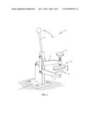
[0011] FIG. 1 is a perspective view illustrating a tool press configured according to one embodiment of the present disclosure.
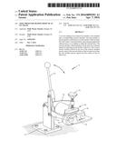
[0012] FIG. 2 is a perspective view illustrating some of the components of a tool press configured according to one embodiment of the present disclosure.
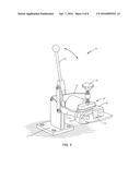
[0013] FIG. 3 is a side perspective view of some of the components of a tool press configured according to one embodiment of the present disclosure.
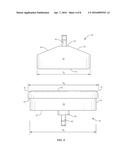
[0014] FIG. 4 is a perspective view of some of the components of a tool press configured according to one embodiment of the present disclosure as seen from another side.
[0015] FIG. 5 is a perspective view illustrating the tool press functioning to shape the boot of an ice skate according to one embodiment of the present disclosure.
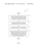
[0016] FIG. 6 is a flow chart illustrating a method for shaping an ice skate boot using a tool press configured according to one embodiment of the present disclosure.
[0017] FIG. 7 is a perspective view illustrating heating circuits associated with some components of a tool press according to one embodiment of the present disclosure.
[0018] FIG. 8 is a perspective view illustrating some components of a tool press according to another embodiment of the present disclosure.
DETAILED DESCRIPTION
[0019] Embodiments of the present disclosure provide a tool press and a corresponding method for shaping selected areas of an ice skate boot that have been determined by a user to cause discomfort. The tool particularly comprises shaping elements that are pressed against the interior and exterior surfaces of the boot to flatten or shape such areas thereby alleviating the discomfort experienced by the user. Some examples of ice skate boots that may be shaped using the shaping elements of the tool include, but are not limited to, those manufactured and sold by companies such as BAUER, CCM, GRAF, REEBOK, and the like.
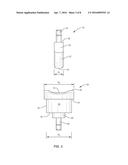
[0020] Turning to the drawings, FIG. 1 is a perspective view illustrating a tool press 10 configured according to one embodiment of the present disclosure. As seen in FIG. 1, tool 10 comprises a bench-mounted tool press; however, those of ordinary skill in the art will readily appreciate that the present disclosure is not limited solely to tools that are mounted to workbenches and the like. In other embodiments, for example, the tool press is not bench-mounted, but instead, comprises a hand-held tool.
[0021] The tool press 10 seen in FIG. 1 comprises a base 12, a lower arm 14, an upper arm 16, an adjustor mechanism 18, and an actuator arm 20. The base 12, as will be appreciated from the figures, comprises a substantially plate comprises of a metal or metal alloy, for example, that fixedly attaches to the surface of a stable underlying platform (e.g., a workbench). A plurality of mechanical fasteners, such as screws and/or bolts, for example, may be used to securely fasten the base 12, and thus, tool 10, to the stable platform.
[0022] The lower and upper arms 14, 16 each pivotably connect to the tool 10. A ram 30 and a receiver 50 are coupled to the tool 10 at the opposite ends (i.e., the terminal ends) of the arms 14, 16, respectively, such that they oppose each other. An adjustor mechanism 18, which in this embodiment comprises a rotatable knob, is disposed on one of the arms 14, 16. In use, the adjustor mechanism 18 moves the receiver 50 towards or away from the ram 30, thereby allowing the user to adjust the distance between the ram 30 and the receiver 50 when attached to the first and second arms, 14, 16.
[0023] In operation, a user places the boot of an ice skate between the ram 30 and the receiver 50 such that the ram 30 contacts an area on the interior surface of the boot that has been determined to undesirably press or rub against the user's foot. This positions receiver 50 to contact an area on the exterior surface of the boot that is opposite the interior surface area contacted by the ram 30. The adjustor mechanism 18 may be employed to adjust the distance between the ram 30 and/or the receiver 50 and the respective interior surfaces of the ice skate boot as needed or desired.
[0024] Once the ram 30 and receiver 50 are properly positioned, the user pulls downwardly on the actuator arm 20 thereby causing the ram 30 and receiver 50 at the terminal ends of the arms 14, 16, to move towards each other. More particularly, pulling downwardly on the actuator arm 20 causes the ram 30 to press against the area on the interior surface of the ice skate boot that is causing discomfort for the user. It also causes receiver 50 to press against the exterior surface of the ice skate boot opposite where the ram 30 is pressing against the interior surface of the boot. By working the actuator arm 20 up and down, and by moving or sliding the skate boot between the ram 30 and receiver 50, the user can ensure that the part of the interior surface of the ice skate boot that was pressing into or rubbing against the user's foot is sufficiently flattened or shaped so as to better conform to the user's foot.
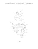
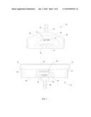
[0025] FIGS. 2-4 are perspective views illustrating some of the structural features of ram 30 and receiver 50 according to one embodiment of the present disclosure. As seen in these figures, ram 30 is a solid, substantially triangularly-shaped member having a sidewall 32, a contact surface 34, and a pair of opposing ramps 34 formed as slanted surfaces that extend from opposing ends of the sidewall 32 up to a substantially flat base surface 38. Extending from the flat base surface 38 is a connector 40 that releasably couples ram 30 to a terminal end of the first arm 14. Such connection methods are known in the art, and thus, are not described in detail here.
[0026] When ram 30 is coupled to the terminal end of the first arm 14, the tool 10 is configured to shape the interior of the ice skate boot according to the present disclosure. More particularly, ram 30 is positioned within the interior of an ice skate boot such that the contact surface 34 contacts, or is proximate, an area on the interior surface of the boot that causes the user pain or discomfort. Typically, such areas comprise jagged sections on the interior surface of the boot, or are parts of the interior surface that press into, or repeatedly rub against, the user's foot. Once positioned, the user operates the actuator arm 20 of tool 10 thereby causing the contact surface 34 of ram 30 to press against the pain-causing area on the interior surface of the boot. Responsive to this pressure, the area on the interior surface of the ice skate boot that presses into or repeatedly rubs against the user's foot cause is shaped or flattened by the contact surface 34 such that it no longer causes the user discomfort.
[0027] As seen in the figures, the contact surface 34 of ram 30 is generally flat, while the peripheral edges of the contact surface 34 are beveled or rounded. The generally flat contact surface 34 allows for the tool 10 to flatten or otherwise modify the shape of as much of a selected area of the interior surface of the boot as possible. The beveled or rounded edges of ram 30 reduce the possibility that ram 30 might cut into the surface of the ice skate boot and/or cause corresponding indentations on the interior surface of the boot.
[0028] As seen in the illustrated embodiment of FIGS. 2-4, ram 30 comprises an elongated member. However, those of ordinary skill in the art should appreciate that this is for illustrative purposes only. Neither the ram 30 nor the receiver 50 is required to be elongated. Rather, as described in more detail later, both the ram 30 and receiver 50 may comprise other shapes and sizes.
[0029] Further, in the disclosed embodiment, ram 30 comprises a unitary structure having a width of d1 (see FIG. 3) and a length of d2 (see FIG. 4). Although the dimensions of ram 30 can be any dimensions needed or desired, the dimensions d1 and d2 are selected such that the ram 30 fits into a cavity formed in the receiver 50.
[0030] Receiver 50 also comprises a generally elongated unitary member comprising a sidewall 52 having an inner surface 54 and an outer surface 56, a cavity 58, and a rim 60. The inner surface 54 of sidewall 52 extends substantially perpendicularly from a floor 62 to form the wall of the cavity 58. Additionally, the sidewall 52 terminates in a rim 60 formed as a lip that defines an opening into the cavity 58. Although not required, the surface of rim 60 comprises a generally flattened surface on opposing longitudinal sides of the receiver 50, while the peripheral edges of rim 60 are beveled or rounded. So shaped, the receiver 50 can press against an exterior surface of the ice skate boot when the contact surface 34 of ram 30 presses against the interior surface of the ice skate boot without undesirably creating indentations into the exterior surface of the boot.
[0031] In some embodiments, the peripheral edges of rim 60 are substantially flush with, or bevel into, one or both of the interior and exterior surfaces 54, 56 of sidewall 52. However, in other embodiments, such as that illustrated in FIGS. 2-4, rim 60 is formed to include an overhang 64 that extends outwardly from the ram 30 generally perpendicularly to the exterior surface 56 of sidewall 52 (see FIGS. 3-4).
[0032] Receiver 50 also comprises a base 66. The base 66 comprises a sturdy surface onto which a coupler 68 is attached. In a manner similar to the coupler 40 of ram 30 above, the coupler 68 of receiver 50 allows the receiver 50 to be releasably coupled to the terminal end of second arm 16 opposite the ram 30.
[0033] As seen in FIGS. 2-4, the sidewall 52 of elongated receiver 50 has a width of about d3 and a length of about d5. Further, the rim 60, formed with overhang 64, has a width of about d4 and a length of about d6. These dimensions may be any dimensions needed or desired, but as stated above, the overhang 64 extends beyond the exterior surface 56 of sidewall 52. Thus, in this embodiment, d4>d3, and d6>d5. Additionally, the cavity 58 is sized and shaped so as to receive at least part of the ram 30. In this embodiment, the cavity 58 is sized so as to allow the ram 30 to be freely inserted into the cavity 58 without becoming bound within the cavity 58. As seen in more detail later, the size of cavity 58 allows for the exterior surface of the ice skate boot to be pressed at least partially into the cavity 58 when the contact surface 34 of ram 30 presses against the interior surface of the ice skate boot.
[0034] As stated above, the rim 60 of receiver 50 is generally flattened on opposing longitudinal sides of the cavity 58. This allows the receiver 50 to press against the exterior surface of the ice skate boot, without indenting the exterior surface of boot 34, when the contact surface 34 of ram 30 is pressed against the interior surface of the ice skate boot.
[0035] However, with conventional tool presses, a receiver may still create unwanted indentations into the exterior of the ice skate boot. This is at least partially due to the force with which the user operates the tool press. Specifically, when the user pulls down on the actuator arm 20, the ram 30 and receiver 50 move towards each other such that each component part (i.e., ram 30 and receiver 50) contacts its respective interior and exterior boot surface. As the user increases the force exerted on the actuator arm 20, the force with which both the ram 30 and the receiver 50 contact their respective boot surfaces also increases.
[0036] In some cases, the respective but opposite forces applied by the ram 30 and receiver 50 could cause one or both of the ram 30 and receiver 50 to indent the interior and/or exterior surface of the ice skate boot. Particularly, the force applied to the actuator arm 20 may cause the ram 30 to indent the interior surface of the ice skate boot and/or the rim 60 of receiver 50 to indent the exterior surface of the boot. Thus, while the contact surface 34 of ram 30 may flatten or shape an area on the interior surface of the boot that causes the user discomfort, the force applied by the user to perform that function can also possibly create another different indentation into the boot.
[0037] Therefore, in one embodiment, the receiver 50 of the present disclosure comprises one or more arcuate notches 70 formed in the rim 60. As seen in the figures, the surface of each arcuate notch 70 is smooth and generally rounded. These arcuate notches 70, which in this embodiment are disposed at opposing ends of the receiver 50, are formed so as to receive a portion of the exterior surface of the ice skate boot when the contact surface 34 of ram 30 is pressed against the interior surface of the ice skate boot. In receiving the exterior surface of the ice skate boot, the arcuate notches 70 help prevent, or at least substantially reduce the chance that the rim 60 will create such undesired indentations into the exterior of the ice skate boot.
[0038] FIG. 5 is a perspective view illustrating how the tool 10 configured with a ram 30 and receiver 50 of the present disclosure may be utilized to shape a surface of an ice skate boot 80 according to one embodiment. FIG. 6 is a flow chart illustrating a method 90 for shaping the ice skate boot 80 using tool 10 according to one embodiment.
[0039] As seen in FIGS. 5-6, the ram 30 and receiver 50 are releasably coupled to the terminal ends of respective arms 14, 16, and an ice skate is positioned therebetween. Specifically, the ice skate is positioned between the ram 30 and the receiver 50 such that generally flat contact surface 34 of ram 30 is positioned on the inside of boot 80 and contacts the part of the interior surface of boot 80 that causes the user discomfort (box 92). Because the ram 30 and the receiver 50 are on opposite arms 14, 16, the receiver 50 will contact or be proximate the exterior surface of ice skate boot 80 at a place on boot 80 that is opposite where the ram 30 contacts the interior surface of the boot 80 (box 94). So positioned, the user can then rotate the adjustor mechanism 18, as needed, to bring the receiver 50 into contact with the exterior surface of the ice skate boot 80 (box 96). So positioned, the rim 60 of receiver 50 contacts the exterior surface of the boot 80. Additionally, as is seen in FIG. 5, the one or more arcuate notches 70 formed in rim 60 receive the exterior surface of the ice skate boot 80.
[0040] To shape the boot 80, the user simply pulls down on the actuator arm 20 (box 98). This movement causes the contact surface 34 of ram 30 to press against the interior surface of the ice skate boot 80, and also causes the rim 60 to press against the exterior surface of the ice skate boot 80. The exterior surface of the ice skate boot 80, as seen in FIG. 5, is pressed at least partially into the cavity 58 of receiver 50, as well as into the one or more arcuate notches 70 formed into the rim 60 of sidewall 52. The user may then move the ice skate boot 80 around relative to the ram and receiver 30, 50 and repeatedly reapply pressure via actuator arm 20 to ensure that other such undesirable spots on the interior of ice skate boot 80 are shaped or flattened.
[0041] Although it is not required, one embodiment of the present disclosure applies heat to one or both of the ram 30 and receiver 50 prior to positioning the ice skate boot 80 between them. Heating the ram 30 and/or receiver 50 indirectly heats the boot 80, thereby facilitating forming or shaping the ice skate boot 80.
[0042] For example, a user may utilize a blow torch or other heat source to heat one or both of the ram 30 and receiver 50 to bring those elements up to an appropriate temperature. The ram 30 and/or receiver 50 may be heated to any desired temperature, but in one embodiment, is heated to be between about 42-185 degrees Fahrenheit. Regardless of the specific temperature, however, the user places the boot 80 between the ram 30 and receiver 50 once those elements have reached their desired temperatures, and operates the actuator arm 20 to apply pressure to the ice skate boot 80 as previously described.
[0043] FIG. 7 illustrates another embodiment in which the ram 30 and receiver 50 each contain a heating circuit 90 to facilitate the heating of those elements. The heating circuit 90 seen in FIG. 8 is very simple; however, this is for illustrative purposes only. Those of ordinary skill in the art readily appreciate that the heating circuit 90 for ram 30 and/or receiver 50 to be as complex as needed or desired.
[0044] As seen in FIG. 7, each heater circuit 90 comprises a power source 92 connected to a heating coil 94. The power source 92 may be any source of electrical power, and is represented in FIG. 7 by an internal battery. However, the power source 92 need not be an internally mounted battery, and may instead be an external device to which the ram 30 and receiver 50 connect. In these latter cases, the external device may comprise a base into which the ram 30 and/or receiver 50 are inserted. The base may be plugged into a power outlet and have user controls to allow the user to control on/off and temperature settings.
[0045] The heating element 94 contacts the sidewalls of their respective ram 30 and receiver 50, and heats the ram 30 and receiver 50 to the desired temperature. A switch and/or a control knob may also be operatively connected to the circuit 90, as is known in the art. Such user controls could allow the user to control whether the heating circuit 90 is on or off, as well as the specific temperature of one or both of the ram 30 and receiver 50.
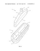
[0046] The present invention may, of course, be carried out in other ways than those specifically set forth herein without departing from essential characteristics of the invention. For example, the illustrated embodiments describe the ram 30 and receiver 50 as comprising elongated members. However, those of ordinary skill in the art will readily appreciate that the present disclosure is not so limited. In another embodiment, seen in FIG. 8, the ram 30 and receiver 50 are shaped as a ball and corresponding cup sized to receive the ball-shaped ram 30. In this embodiment, the cup comprises a cavity 58 formed by the sidewall 52; however, the rim 60 of the cup-shaped receiver 50 also comprises one or more arcuate notches 70 formed therein. As above, the arcuate notches 70 will receive the exterior surface of boot 80, thereby preventing or eliminating the undesirable indentations caused by the rim 60 of the cup-shaped receiver 50 when the ball-shaped ram 30 is pressed against the interior surface of boot 80.
[0047] Therefore, the present embodiments are to be considered in all respects as illustrative and not restrictive, and all changes coming within the meaning and equivalency range of the appended claims are intended to be embraced therein.
User Contributions:
Comment about this patent or add new information about this topic:
Images included with this patent application:
 |  |
 |  |
 |  |
 |  |
 |
| New patent applications from these inventors: | |
| Date | Title |
|---|---|
| 2017-02-16 | Mounting assembly for a face shield with an enhanced base |
| 2016-11-17 | Mounting assembly for a face shield |
| 2015-03-05 | Mounting assembly for a face shield |
| 2012-09-06 | Mounting assembly for a face shield |
| 2012-09-06 | Mounting assembly for a face shield |
| Top Inventors for class "Boot and shoe making" | |
| Rank | Inventor's name |
|---|---|
| 1 | James C. Meschter |
| 2 | Frederick J. Dojan |
| 3 | Bhupesh Dua |
| 4 | Alexandre Baudouin |
| 5 | Elizabeth Langvin |