Patent application title: Fluid cooling pad system utilizes compressed air as a cooling source
Inventors:
Edward Lau (Markham, CA)
IPC8 Class: AF28D1500FI
USPC Class:
16510434
Class name: Heat exchange intermediate fluent heat exchange material receiving and discharging heat including means to move gaseous heat exchange material
Publication date: 2016-03-17
Patent application number: 20160076818
Abstract:
A fluid cooling pad system 10 utilizes compressed air as a cooling
source. Compressed air 205 can provide a cooling effect for the fluid
cooling pad system 10. By using a compressed air cartridge 300 to store
the compressed air 205, the fluid cooling pad system is easy to maintain
and the fluid cooling pad system size can be reduced. The cooling effect
can also be extended by replacing an empty compressed air cartridge 300
with a filled compressed air cartridge 300. By further including a manual
air pump 500 or powered air pump 600, compressed air cartridge 300 can be
refilled. The fluid cooling pad system 10 is also expandable. By
connecting connection tubes 107 to multiple fluid cooling pads 100, user
can attach the fluid cooling pads 100 to multiple areas simultaneously,
for example and without limitation, on wearable garments such as caps,
helmets, and/or applied directly to the user's body.Claims:
1. The fluid cooling pad system 10 utilizes compressed air as a cooling
source, comprises: (a) one or more fluid cooling pads 100; (b) each of
said fluid cooling pad 100 comprises a fluid cooling tube 103; (c) heat
transfer fluid 203; (d) a fluid container 202 to contain said heat
transfer fluid 203; (e) a fluid transfer pump 106 to transfer said heat
transfer fluid 203 from said fluid container 202 to said fluid cooling
tube 103 of said fluid cooling pad 100; (f) connection tubes 107; an
outlet 114 of said fluid container 202 is connected to one end of a
connection tube 107; another end of said connection tube 107 is connected
to an inlet 118 of said fluid pump 106; an outlet 119 of said fluid pump
106 is then connected to one end of a second connection tube 107; another
end of said second connection tube 107 is connected to an inlet 111 of
said fluid cooling pad 100; an outlet 112 of said fluid cooling pad 100
is then connected to one end of a third connection tube 107; another end
of said third connection tube 107 is connected to an inlet 115 of said
fluid container 202 to form a closed flowing path where said heat
transfer fluid can be circulated in said flowing path; (g) a compressed
air cartridge 300 for storing compressed air; (h) a compressed air
connector 207 for controlling air flow of compressed air that is stored
in said compressed air cartridge 300; and (i) a compressed air channel
211; an inlet 210 of said compressed air channel 211 that is connected to
an outlet 208 of said compressed air connector 207; an outlet 206 of said
compressed air channel 211 is nearly touching a surface of said fluid
container 202; compressed air stored in said compressed air cartridge 300
is released by said compressed air connector 207 and said compressed air
is ejected from a compressed air valve 301 of said compressed air
cartridge 300 to said outlet 208 of said compressed air connector 207;
then said compressed air enters said inlet 210 of said compressed air
channel 211 and exits through said outlet 208 of said compressed air
channel 211; and said compressed air is ejected from said outlet of said
compressed air channel 202, rapidly lowers the temperature of said heat
transfer fluid 203 that is stored inside said fluid container 202.
2. The system of claim 1 wherein said compressed air cartridge 300 is replaceable.
3. The system of claim 1 wherein said fluid cooling pad system 10 further includes a thermal insulated container 201 to contain said fluid container 202 to reduce heat loss between said heat transfer fluid 203 of said fluid container 202 and the surrounding environment.
4. The system of claim 1 wherein said fluid container 202 further includes one or more ice packs 204 to lower the temperature of said heat transfer fluid 203.
5. The system of claim 1 wherein said fluid cooling pad system 10 further includes a manual air pump 500 to refill said compressed air cartridge 300. An outlet 501 of said manual air pump 500 is connected to an inlet 209 of said compressed air connector 207. When air is pumped, said air is ejected from said outlet 501 of said manual pump 500 and stored into said compressed air cartridge 300 via an inlet 209 of said compressed air connector 207.
6. The system of claim 1 wherein said fluid cooling pad system 10 further includes a powered air pump 600 to refill said compressed air cartridge 300. An outlet 601 of said powered air pump 600 is connected to an inlet 209 of said compressed air connector 207. When air is pumped, said air is ejected from said outlet 601 of said powered air pump 600 and stored into said compressed air cartridge 300 via an inlet 209 of said compressed air connector 207.
7. The system of claim 1 wherein said fluid cooling pad system 10 further includes a vortex tube 1000 to increase the cooling effect. Said outlet 206 of said compressed air channel 211 is connected to an inlet 1009 of said vortex tube 1000. A cold end 1008 of said vortex tube 1000 is placed near a surface of said fluid container 202. Said compressed air ejected from said outlet 206 of said compressed air channel 211 enters said inlet 1009 of said vortex tube 1000 and cool air is generated by said vortex tube 1000. Said cool air is ejected from said cold end 1008 of said vortex tube 1000 and rapidly lowers the temperature of said heat transfer fluid 203 that is stored inside said fluid container 202.
Description:
CROSS-REFERENCE TO RELATED APPLICATIONS
[0001] This application claims the benefit of U.S. Provisional Application No. 61/871,294, filed on Aug. 28, 2013, which application is incorporated herein by reference.
STATEMENT REGARDING FEDERALLY SPONSORED RESEARCH OR DEVELOPMENT
[0002] Not Applicable
THE NAMES OF THE PARTIES TO A JOINT RESEARCH AGREEMENT
[0003] Not Applicable
INCORPORATION-BY-REFERENCE OF MATERIAL SUBMITTED ON A COMPACT DISC
[0004] Not Applicable
BACKGROUND
[0005] 1. Field
[0006] The disclosed and claimed concept relates to heat transfer systems, particularly to a fluid cooling pad system which utilizes compressed air as a cooling source.
[0007] 2. Description of Related Art
[0008] Conventional fluid cooling systems for wearable garments use heat transfer fluid to draw heat away from the user's body and utilize ice as a cooling source to lower the temperature of the heat transfer fluid. However, temperature of the user's body and the surrounding environment quickly raises the temperature of the heat transfer fluid. In order to maintain the cooling effect, user must constantly add ice to lower the temperature of the heat transfer fluid. Those conventional fluid cooling systems require plenty of ice and storage space, which is very inconvenient for many users.
BRIEF DESCRIPTION OF THE DRAWINGS
[0009] A full understanding of the disclosed and claimed concept can be obtained from the following description, read in conjunction with the accompanying drawings:
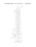
[0010] FIG. 1 shows an embodiment of a fluid cooling pad system which utilizes compressed air as a cooling source. The compressed air is stored in a compressed air cartridge;
[0011] FIG. 2 shows the same embodiment of the fluid cooling pad system as shown in FIG. 1 that further includes a manual pump to refill the compressed air cartridge;
[0012] FIG. 3 shows the same embodiment of the fluid cooling pad system as shown in FIG. 1 that further includes a powered air pump to refill the compressed air cartridge;
[0013] and
[0014] FIG. 4 shows an embodiment of a vortex tube for generating cold air.
DETAILED DESCRIPTION
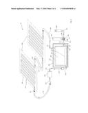
[0015] An embodiment of a fluid cooling pad system 10 utilizes compressed air 205 as a cooling source, in accordance with the disclosed and claimed concept, is indicated generally in FIG. 1. The fluid cooling pad system 10 comprises at least one or more fluid cooling pad 100, connection tubes 107, a fluid pump 106, a cooling container 200, and a compressed cartridge 300 as a cooling source.
[0016] As shown in FIG. 1, a fluid cooling pad 100 comprises a housing 101 that comprises the fluid cooling tube 103 that is arranged, for example and without limitation, in a zigzag pattern. The housing 101 can be made of, for example and without limitation, fabric or plastic. The fluid cooling pad 100 can be, for example and without limitation, attached to wearable garments, such as caps, helmets, and/or applied directly to the user's body. The fluid cooling tube 103 provides a channel for heat transfer fluid 203 to flow through and draws heat away from the user's body.
[0017] In accordance with the disclosed and claimed concept, the fluid cooling pad system 10 can have one or more fluid cooling pads 100. By connecting an outlet 112 of a fluid cooling pad 100 to one end of a connection tube 107 and connecting another end of the connection tube 107 to an inlet 111 of another fluid cooling pad 100, the fluid cooling pad system 10 can have multiple fluid cooling pads 100 connected together.
[0018] As shown in FIG. 1, the cooling container 200 comprises a thermal insulated container 201, a fluid container 202, and heat transfer fluid 203. The heat transfer fluid 203 is stored inside the fluid container 202, and the fluid container 202 is placed inside the thermal insulated container 201. The purpose of the thermal insulated container 201 is to reduce heat loss between the heat transfer fluid 203 and the surrounding environment. Additionally, an ice pack 204 can be placed inside the fluid container 202 to lower the temperature of the heat transfer fluid 203.
[0019] An outlet 114 of the fluid container 202 is connected to one end of a connection tube 107; another end of the connection tube 107 is connected to an inlet 118 of the fluid pump 106; then an outlet 119 of the fluid pump 106 is connected to one end of a second connection tube 107; another end of the second connection tube 107 is connected to an inlet 111 of a fluid cooling pad 100. An outlet 112 of the fluid cooling pad 100 is then connected to one end of a third connection tube 107. Another end of the third connection tube 107 can either be connected to an inlet 111 of another fluid cooling pad 100 to form a multiple fluid cooling pads configuration or be connected to an inlet 115 of the fluid container 202 to form a closed circular flowing path. The fluid pump 106 can be a manual fluid pump or a powered fluid pump. If the fluid pump 106 is a powered fluid pump, the fluid pumping operation can be triggered by, for example and without limitation, the user manually, an electronic thermal sensor, or an electronic timer.
[0020] An outlet 208 of a compressed air connector 207 is connected to an inlet 210 of a compressed air channel 211. The compressed air channel 211 is extended through a wall of the thermal insulated container 201 and an outlet 206 of the compressed air channel 211 is nearly touching a surface of the fluid container 202. For safety purposes, the compressed air connector 207 has a built-in pressure regulator to automatically cut the flow of the compressed air at a predetermined pressure.
[0021] The embodiment of the fluid cooling pad system 10 utilizes compressed air 205 as a cooling source. The compressed air 205 is stored in the compressed cartridge 300. A compressed air valve 301 of the compressed air cartridge 300 is connected to the compressed air connector 207. The compressed air 205 is released by the compressed air connector 207 and the compressed air 205 is ejected from the compressed air valve 301 of the compressed air cartridge 300 to the outlet 208 of the compressed air connector 207; the compressed air 205 then enters the inlet 210 of the compressed air channel 211 and exits through the outlet 206 of the compressed air channel 211. The compressed air 205 provides a cooling effect and rapidly lowers the temperature of the heat transfer fluid 203 that is stored inside the fluid container 202. The release of the compressed air operation can be triggered by, for example and without limitation, the user manually, an electronic thermal sensor, or an electronic timer. If the compressed air cartridge 300 is either empty or pressure is insufficient, it can be simply replaced with another compressed air cartridge 300. By using the compressed air cartridge 300 to store the compressed air 205, the fluid cooling pad system 10 is easy to maintain and the system size can be significantly reduced.
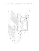
[0022] FIG. 2 shows the same embodiment of the fluid cooling pad system 10 as shown in FIG. 1 that further includes a manual pump 500 to refill the compressed air cartridge 300. User can refill the compressed air cartridge 300 by pumping air into the compressed air cartridge 300. An outlet 501 of the manual air pump 500 is connected to an inlet 209 of the compressed air connector 207. When air is pumped, the air is ejected from the outlet 501 of the manual air pump 500 and stored into the cartridge 300 via an inlet 209 of the compressed air connector 207. The user can pump and refill the cartridge 300 whenever the air pressure in the compressed air cartridge 300 is low.
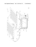
[0023] FIG. 3 shows the same embodiment of the fluid cooling pad system 10 as shown in FIG. 1 that further includes a powered pump 600 to refill the compressed air cartridge 300. User can refill the compressed air cartridge 300 by pumping air into the compressed air cartridge 300. An outlet 601 of the powered air pump 600 is connected to an inlet 209 of the compressed air connector 207. When air is pumped, the air is ejected from the outlet 601 of the powered air pump 600 and stored into the cartridge 300 via an inlet 209 of the compressed air connector 207. The compressed air cartridge refill operation can be triggered by, for example and without limitation, the user manually or by a pressure sensor.
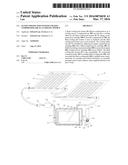
[0024] FIG. 4 shows an embodiment of a vortex tube 1000. The vortex tube 1000 spins compressed air to produce hot and cold air streams. Compressed air 1001 enters an inlet 1009 of the vortex tube 1000; a vortex generation chamber 1002 causes the input compressed air 1001 to rotate at a very high speed and forces it towards a longer side 1007 of the vortex tube 1000 to generate hot air. At the end of the longer side 1007 of the vortex tube 1000, a portion of air exits through a needle valve 1003 becoming hot air and exits through the hot air exhaust 1005. The remaining air is forced back 1004 through the center of the incoming air stream at a slower speed. The heat in the slower moving air is transferred to the faster moving incoming air and the temperature of the slower moving air becomes very low. The slower moving cold air 1006 flows through the center of the vortex tube 1000 and exits through the cold air exhaust port 1006.
[0025] The embodiment of the vortex tube 1000 can be added to the embodiment of the fluid cooling pad system 10 to increase the cooling effect of the compressed air. With reference to FIG. 1, the outlet 206 of the compressed air channel 211 of the first embodiment of the fluid cooling pad system 10 can be connected to the inlet 1009 of the vortex tube 1000. The cold end 1008 of the vortex tube 1000 is placed near the surface of the fluid container 202. The compressed air 205 enters the inlet 1009 of the vortex tube 1000 and the cool air 1006 generated by the vortex tube 1000 rapidly lowers the temperature of the heat transfer fluid 203 that is stored inside the fluid container 202.
[0026] It thus can be seen that the fluid cooling pad system 10 utilizes compressed air as a cooling source, which is very convenient and provides an extended cooling effect. The fluid cooling pad system 10 is also expandable. By connecting connection tubes 107 to multiple fluid cooling pads 100, the user can attach the fluid cooling pads 100 to multiple areas simultaneously, for example and without limitation, on wearable garments such as caps, helmets and/or applied directly to the user's body.
[0027] While specific embodiments of the disclosed and claimed concept relates generally to heat transfer systems have been described in detail, it will be appreciated by those skilled in the art that various modifications and alternatives to these details could be developed. Accordingly, the particular arrangements disclosed are meant to be illustrative only and not limiting as to the scope of the disclosed and claimed concept which is to be given the full breadth of the claims appended and any and all equivalents thereof.
User Contributions:
Comment about this patent or add new information about this topic:
Images included with this patent application:
 |  |
 |  |
 |
| Similar patent applications: | |
| Date | Title |
|---|---|
| 2016-05-19 | Compressed gas storage unit |
| 2015-12-31 | Media pads for gas turbine |
| 2016-05-19 | Method and system for a dual loop coolant system |
| 2012-02-16 | Fluid cooling |
| 2012-06-07 | Foam composition |
| New patent applications in this class: | |
| Date | Title |
|---|---|
| 2016-05-05 | Heat exchanger |
| 2016-03-31 | Single actuator-operated cooling jet apparatus |
| 2016-02-04 | Gas storage modules, apparatus, systems and methods utilizing adsorbent materials |
| 2016-01-28 | Aircraft gaseous cooling system |
| 2015-11-26 | Cooling device, and heating element housing device equipped with same |
| New patent applications from these inventors: | |
| Date | Title |
|---|---|
| 2016-02-18 | Electronic device and gesture input method of item selection |
| Top Inventors for class "Heat exchange" | |
| Rank | Inventor's name |
|---|---|
| 1 | Levi A. Campbell |
| 2 | Chun-Chi Chen |
| 3 | Tai-Her Yang |
| 4 | Robert E. Simons |
| 5 | Richard C. Chu |