Patent application title: IMPROVED EXTERNAL FIXATORS
Inventors:
Xavier Renard (Vauhallan, FR)
Philippe Pelissier (Merignac, FR)
IPC8 Class: AA61B1760FI
USPC Class:
606 54
Class name: Instruments orthopedic instrumentation external fixation means
Publication date: 2016-03-10
Patent application number: 20160066955
Abstract:
A resilient external fixator between first and second bone portions
includes a spring 11 of axis 12, a body 14, elements 15 for mounting the
body to co-operate with the spring, a pin 16 fastened to the first bone
and passing through the spring, a second body 22 including a base 122 and
a projecting portion 44 that is secured to the base, one end 47 of the
helical spring being mounted in co-operation about the projecting
portion, and elements 24 for connecting the body with the bone portion
O2 and the helical spring. The projecting portion presents a section
that increases in continuous manner from its free end 48 until it reaches
its end 46, the end 47 of the spring having an inside section that is
greater than the section of the free end 48 and less than the
cross-section of the end 46.Claims:
1. A resilient external fixator between first and second bone portions
(O1, O2), comprising: a helical spring (11) defined along a
first axis (12); a first body (14); first means (15) for mounting said
first body (14) to co-operate with said helical spring (11); a first pin
(16) suitable for being fastened to said first bone portion (O1),
said first pin (16) being oblong in shape and defined along a second axis
(17), said helical spring being suitable for turning relative to the
first body about the first axis (12) and the first pin (16) passes
through said helical spring (11); means (19) for mounting said first pin
(16) to co-operate with said first body (14) so that said second axis
(17) forms a non-zero angle with the first axis (12); a second body (22)
comprising a base (122) and a projecting portion (44) secured, by one
(46) of its ends, to said base (122), one (47) of the ends of the helical
spring (11) being mounted in co-operation around said projecting portion
(44); and means (24) for connecting said second body (22) with said
second bone portion (O2) and said helical spring (11); the fixator
being characterized by the fact that said projecting portion (44)
presents a cross-section that increases in relatively continuous manner
from its free end (48) until it reaches its end (46) that is secured to
said base (122), said one (47) of the ends of the helical spring having
an inside cross-section that is greater than the cross-section of the
free end (48) of said projecting portion and less than the cross-section
of the end (46) of said projecting portion that is secured to said base
(122).
2. A fixator according to claim 1, characterized by the fact that the projecting portion that presents a cross-section that increases in relatively continuous manner from its free end (48) until it reaches its end (46) that is secured to said base (122) is conical in shape.
3. A fixator according to claim 2, characterized by the fact that the projecting portion that presents a cross-section that increases in relatively continuous manner from its free end (48) until it reaches its end (46) that is secured to said base (122) is in the shape of a circular cone.
Description:
[0001] The present invention relates to improving resilient external
fixators suitable for being mounted to co-operate with two bone portions
between which it is desired to exert traction or else distraction, and
finding a particularly advantageous application in treating joint
fractures by distraction on the principle of ligamentotaxis in which the
traction exerted on either side of the fracture reduces the displacement
of the fragments and holds them in a position suitable for encouraging
remodeling of the joint.
[0002] The Applicant has made an external fixator that forms the subject matter of European patent No 1 898 815 referred to below as EP-XR.
[0003] That resilient external fixator between first and second bone portions comprises a helical spring defined along a first axis, a first body, first means for mounting the first body to co-operate with the helical spring, a first pin suitable for being fastened to said first bone portion, the first pin being oblong in shape and defined along a second axis, the helical spring being suitable for turning relative to the first body about the first axis and the first pin passing through said helical spring, means for mounting the first pin to co-operate with the first body so that the second axis forms a non-zero angle with the first axis, a second body comprising a base and a projecting portion secured, by one of its ends, to the base, one of the ends of the helical spring being mounted in co-operation around the projecting portion, and means for connecting the second body with the second bone portion and said helical spring.
[0004] The improvement made to the above-defined fixator consists in the projecting portion presenting a cross-section that increases in relatively continuous manner from its free end until it reaches its end that is secured to the base, said one of the ends of the helical spring having an inside cross-section that is greater than the cross-section of the free end of the projecting portion and less than the cross-section of the end of the projecting portion that is secured to the base.
[0005] Other characteristics and advantages of the invention appear from the following description given with reference to the accompanying drawings by way of non-limiting illustration, and in which:
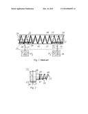
[0006] FIG. 1 is a diagrammatic side view showing an embodiment of the resilient external fixator as defined in document EP-XR; and
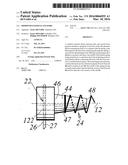
[0007] FIG. 2 shows, in a diagram taken in combination with the diagram of FIG. 1, an embodiment of a portion of the resilient external fixator of the invention.
[0008] Firstly, it is stated that in the present description, if the adverb "substantially" is associated with a qualifier of a given means, that qualifier may be understood either in a strict sense or in an approximate sense.
[0009] With reference to FIG. 1, the invention described below relates to a resilient external fixator suitable for exerting a resilient force of adjustable intensity between first and second bone portions O1 and O2, and it finds a particularly advantageous application as an external fixator for exerting traction or distraction, both of which can be modulated, between two bones or two bone fractions of a finger, e.g. between two phalanges.
[0010] In the embodiment shown in FIG. 1, the external fixator essentially comprises: a helical spring 11 defined along a first axis 12; a first body 14; first means 15 for mounting said first body 14 to co-operate with the helical spring 11 so that the helical spring is capable of pivoting relative to the first body substantially about the first axis 12; a first pin 16 suitable for being fastened to the first bone portion O1, said first pin 16 being oblong in shape along a second axis 17; and means for mounting the first pin 16 to co-operate with the first body 14 so that it passes through the helical spring 11 and so that the second axis 17 forms a non-zero angle with the first axis 12.
[0011] In an advantageous embodiment, the pin 16 is a bone pin that is well known in itself, of circularly cylindrical or similar shape, and having an end 46 for penetrating into a bone, which end may include a bone thread, e.g. of the self-tapping type.
[0012] By way of example, the means 19 for mounting the first pin 16 to co-operate with the first body 14 are constituted by a through orifice made in the body 14 and of cross-section complementary to that of the pin 16, and advantageously by means for locking the pin in the through orifice and thus relative to the first body 14, such as a fastener screw or the like.
[0013] The external fixator of the invention also includes a second body 22 and means 24 for connecting the second body 22 with the second bone portion O2 and with the helical spring 11.
[0014] In the embodiment shown in FIG. 1, the means 24 for connecting the second body 22 with the second bone portion O2 and the helical spring 11 comprise: second means 25 for mounting the second body 22 to co-operate with the helical spring 11 so as to allow the spring to pivot relative to the second body about the first axis 12; a second pin 26 suitable for being fastened to the second bone portion O2 and defined along a third axis 27; and means 29 for mounting the second pin 26 to co-operate with the second body 22 so as to pass through the helical spring 11 and so that the third axis 27 forms a non-zero angle relative to the first axis 12.
[0015] In an advantageous embodiment, the helical spring 11 has non-touching turns and it is made of a material such as stainless steel, or the like.
[0016] By way of example, the second body 22 comprises, as shown in FIG. 4 of document EP-XR, a base 122 and a projecting portion 44 secured, by one 46 of its ends, to the base 122, an end 47 of the helical spring 11 being mounted in co-operation around the projecting portion 44.
[0017] The improvement made to the above-defined fixator consists in the projecting portion 44 presenting a cross-section that increases in relatively continuous manner from its free end 48 until it reaches its end 46 that is secured to the base 122, the helical spring having an inside cross-section that is greater than the cross-section of the free end 48 of the projecting portion and less than the cross-section of the end 46 of the projecting portion that is secured to the base 122.
[0018] In another characteristic of the invention, the projecting portion 44 is conical in shape, and is preferably in the shape of a circular cone.
[0019] The improved resilient external fixator of the invention presents an advantage other than those of the fixator of the prior document referenced above.
[0020] As a result of the circularly cylindrical shape of the projecting portion 44 of the prior art fixator, the spring 11 could, for various reasons (vibration, friction, etc.), turn about its longitudinal axis, resulting in an involuntary modification of the strength of the force applied between the two bone portions O1, O2.
[0021] In contrast, as a result of the conical shape of the projecting portion 44 of the fixator of the invention, and after adjustment of the spring 11, its end 47 becomes jammed on the conical surface of said projecting portion, this jamming possibly also being accentuated by the practitioner while adjusting the fixator by causing the spring to turn a little about its longitudinal axis, the last turn of the end 47 of the spring thus expanding elastically and increasing friction against the projecting portion.
User Contributions:
Comment about this patent or add new information about this topic:
Images included with this patent application:
 |  |
| Similar patent applications: | |
| Date | Title |
|---|---|
| 2016-01-07 | Mini-rail external fixator |
| 2016-02-04 | External fixator strut |
| 2016-03-03 | Low profile intraluminal filters |
| 2016-03-10 | External fixation system |
| 2016-03-24 | External fixator |
| New patent applications in this class: | |
| Date | Title |
|---|---|
| 2022-05-05 | Clamping devices for external fixation device |
| 2016-04-07 | Anatomic external fixation system |
| 2016-03-31 | Transosseous ribbon wire devices and a system and method for using the devices |
| 2016-01-28 | External fixing device, for treating bone fractures |
| 2015-12-10 | Multi-locking external fixation clamp |
| New patent applications from these inventors: | |
| Date | Title |
|---|---|
| 2016-02-25 | System for joining two blood vessels |
| Top Inventors for class "Surgery" | |
| Rank | Inventor's name |
|---|---|
| 1 | Lutz Biedermann |
| 2 | Roger P. Jackson |
| 3 | Wilfried Matthis |
| 4 | Frederick E. Shelton, Iv |
| 5 | Joseph D. Brannan |