Patent application title: METHOD FOR MANUFACTURING HOLLOW HYDRO-FORMED PRODUCT using MULTI-TUBE ASSEMBLY
Inventors:
Young Hoon Moon (Busanjin-Gu Busan, KR)
Byeong Don Joo (Yeonje-Gu Busan, KR)
Sang Yoon Kim (Yeonje-Gu Busan, KR)
IPC8 Class: AB21D26051FI
USPC Class:
72 61
Class name: By application of fluent medium, or energy field using fixed die expanding hollow work
Publication date: 2015-11-26
Patent application number: 20150336154
Abstract:
A method for manufacturing a hollow hydro-formed product using a
multi-tube assembly is provided, which comprises the steps of: (a) stably
placing a multi-tube assembly in a Die, the hollow inner tube having
fluid channel holes radially formed therethrough; (b) injecting fluid
into the inner periphery of the inner tube; (c) applying fluid pressure
to the inner periphery of the outer tube by the fluid while the fluid is
discharged through the fluid channel holes of the inner tube; and (d)
obtaining a formed product having an intended outer peripheral shape
completed according to diameter-enlargement and plastic deformation of
the outer tube. The inner periphery of the outer tube is pressed and
hydro-formed by discharging the fluid through the fluid channel holes of
the inner tube formed through the inner tube of the multi-tube assembly.Claims:
1. A method for manufacturing a hollow hydroformed product using a
multi-tube assembly, the method comprising the steps of: (a) loading a
multi-tube assembly into a die, the multi-tube assembly including a
hollow outer tube and a hollow inner tube inserted into the hollow outer
tube, the hollow inner tube having a plurality of fluid channel holes
radially formed on the inner peripheral surface thereof; (b) injecting
fluid into the inner tube so as to be supplied to the inner periphery of
the inner tube; (c) applying a hydraulic pressure of the fluid to the
inner periphery of the outer tube while the fluid flows out of the inner
tube through the fluid channel holes of the inner tube; and (d)
subjecting the outer tube to bulging and plastic deformation to obtain a
finally formed product having a desired outer peripheral shape.
2. The method according to claim 1, wherein the inner tube is implemented as a multi-layered tube configured such that at least two hollow tubes are inserted into the outer tube, each of the hollow tubes having a plurality of flow channel holes formed thereon so as to fluidically communicate each other.
3. The method according to claim 1, wherein the outer tube and the inner tube are made of heterogeneous materials.
4. The method according to claim 1, wherein the flow rate of the fluid injected into the inner tube in step (b) is maintained to be equal to that of the fluid flowing out of the inner tube through the fluid channel holes of the inner tube in step (c) so that only the outer tube is plastic-deformed.
5. The method according to claim 1, wherein the flow rate of the fluid injected into the inner tube in step (b) is determined within a range in which a pressure difference caused by a difference in the flow rate of the fluid supplied to the inner periphery and the outer periphery of the inner tube is less than a yield stress of the inner tube so that only the outer tube is plastic-deformed.
Description:
TECHNICAL FIELD
[0001] The present invention relates to a method for manufacturing a hollow hydroformed product using a multi-tube assembly, and more particularly, to such a method for manufacturing a hollow hydroformed product using a multi-tube assembly, in which a hollow multi-tubular part can be fabricated irrespective of formability of an inner tube, shaping precision can be greatly improved, and a hollow part having a desired shape can be fabricated without any deformation of the inner tube.
BACKGROUND ART
[0002] A piping system is widely used as a means that carries or transfer fluids, but is mostly configured as a single-layered tube. Thus, there is a risk of an unexpected accident due to natural corrosion, aging, local damage inside the pipe, and the like. In addition, the fluid transfer distance is long, thus making the inspection and monitoring for safety difficult and leading to an increase in repair and maintenance costs.
[0003] A two-layered tube has been developed to solve the above-mentioned problems. The two-layered tube is configured such that inner and outer tubes made of the same material or heterogeneous materials are joined to each other. In addition, the inner tube is mainly made of a corrosion-preventive material. Since the two-layered tube has significantly excellent properties in terms of airtightness, reliability, burst resistance, on-line detection, and the like compared to the single-layered tube, it can be widely used in petrochemical installations, power plants, or mechanical parts, and so forth.
[0004] A method for manufacturing the two-layered tube includes various techniques such as welding, mechanical extrusion, exclusive forming, tube hydroforming (H/F), etc. In particular, among them, the tube hydroforming process is a technology that utilizes hydraulic pressure to form a tube into desired shapes inside die cavities. The tube hydroforming process has advantages in that a product with precision can be produced due to its improved structural strength and stiffness and lightweightness can be achieved due to a reduction in the number of parts. By virtue of these advantages, the tube hydroforming process is utilized in a variety of applications such as automobile parts industry, petrochemical installations, power plants, and piping systems, the demand for the tube hydroforming process is expected to be continuously increased.
[0005] Meanwhile, recently, hydroformed products produced by a hydroforming technology using a multi-layered tube, i.e., a multiplied tube are applied to pipelines, etc., and are also advantageous in that they can be selectively or complexly given the necessary properties such as corrosion resistance, strength, formability, and abrasion resistance.
[0006] In this connection, Korean Patent Laid-Open Publication No. 2010-0121015 discloses a multi-layered tube using high-pressure tube hydroforming and manufacturing method thereof, in which fluid is supplied to an inner tune 10 having a diameter smaller than that of an outer tube 20 in a state in which the inner tube 10 has been inserted into the outer tube 20 to expand or bulge the inner tube so that the inner tube and the outer tube is coupled to each other to thereby manufacture a multi-layered tube as shown in FIG. 1.
[0007] The method disclosed in the above document is directed to a method in which a hydraulic pressure is applied to the inner peripheral surface of the inner tube to form the tubes into desired shapes, and features that the inner tube 10 and the outer tube 20 have the same shape and are in close contact with each other.
[0008] However, the above conventional prior art entails problems in that since the inner tube must be formed together with the outer tube to produce a hollow part having the combined physical properties, it is difficult to select a material in consideration of formability of the inner tube, and in that shaping precision is significantly degraded after formation due to a difference in the elastic restoration amount between the inner and outer tubes upon the removal of the hydraulic pressure being applied to the inner tube.
DISCLOSURE OF INVENTION
Technical Problem
[0009] Accordingly, the present invention has been made in order to solve the above-described problems occurring in the prior art, and it is an object of the present invention is to provide a method for manufacturing a hollow hydroformed product using a multi-tube assembly in which a hollow multi-tubular part can be fabricated irrespective of formability of an inner tube, and shaping precision can be greatly improved.
[0010] Another object of the present invention is to provide a method for manufacturing a hollow hydroformed product using a multi-tube assembly, in which only an outer tube is selectively plastic-deformed without any deformation of an inner tube so that a hollow part having a desired shape can be fabricated.
Technical Solution
[0011] To achieve the above object, the present invention provides a method for manufacturing a hollow hydroformed product using a multi-tube assembly, the method including the steps of: (a) loading a multi-tube assembly into a die, the multi-tube assembly including a hollow outer tube and a hollow inner tube inserted into the hollow outer tube, the hollow inner tube having a plurality of fluid channel holes radially formed on the inner peripheral surface thereof; (b) injecting fluid into the inner tube so as to be supplied to the inner periphery of the inner tube; (c) applying a hydraulic pressure of the fluid to the inner periphery of the outer tube while the fluid flows out of the inner tube through the fluid channel holes of the inner tube; and (d) subjecting the outer tube to bulging and plastic deformation to obtain a finally formed product having a desired outer peripheral shape.
[0012] Preferably, the inner tube may be implemented as a multi-layered tube configured such that at least two hollow tubes are inserted into the outer tube, each of the hollow tubes having a plurality of flow channel holes formed thereon so as to fluidically communicate each other.
[0013] Also, the outer tube and the inner tube may be made of heterogeneous materials.
[0014] In addition, preferably, the flow rate of the fluid injected into the inner tube in step (b) may be maintained to be equal to that of the fluid flowing out of the inner tube through the fluid channel holes of the inner tube in step (c) so that only the outer tube is plastic-deformed.
[0015] In addition, the flow rate of the fluid injected into the inner tube in step (b) may be determined within a range in which a pressure difference caused by a difference in the flow rate of the fluid supplied to the inner periphery and the outer periphery of the inner tube is less than a yield stress of the inner tube so that only the outer tube is plastic-deformed.
Advantageous Effects
[0016] The method for manufacturing a hollow hydroformed product using a multi-tube assembly of according to an embodiment of the present invention as constructed above has an advantageous effect in that in the production of a hollow part having the combined physical properties through the combination of materials, the inner periphery of the outer tube is pressurized with fluid F while the fluid F flows out of the inner tube through the flow channel holes formed on the inner tube, and then the outer tube is subjected to the plastic deformation to thereby obtain a formed product having a desired outer peripheral shape. Thus, a hollow multi-tubular part can be fabricated irrespective of formability of the inner tube, and shaping precision can be greatly improved.
[0017] In addition, the flow rate of fluid injected into the inner tube is maintained to be equal to that of fluid flowing out of the inner tube through the fluid channel holes of the inner tube or is adjusted within a range in which a pressure difference caused by a difference in the flow rate of the fluid supplied to the inner periphery and the outer periphery of the inner tube is less than a yield stress of the inner tube so that only the outer tube is selectively subjected to the plastic deformation, and thus a hollow part having a desired shape can be fabricated without any deformation of an inner tube.
BRIEF DESCRIPTION OF THE DRAWINGS
[0018] The above as well as the other objects, features and advantages of the present invention will be more apparent from the following detailed description taken in conjunction with the accompanying drawings, in which:
[0019] FIG. 1 is a process flow chart illustrating the main processes of a method for manufacturing a two-layered tube using a conventional tube hydroforming process according to the prior art;
[0020] FIG. 2 is a block diagrammatic flow chart illustrating a method for manufacturing a hollow hydroformed product using a multi-tube assembly according to an embodiment of the present invention;
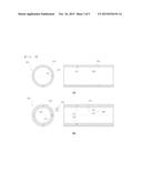
[0021] FIG. 3 illustrates the transverse and longitudinal cross-sectional views of modifications of a multi-tube assembly according to the present invention;
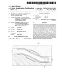
[0022] FIG. 4 is a process flow chart illustrating a longitudinal sectional plane by process in a method for manufacturing a hollow hydroformed product using a multi-tube assembly according to an embodiment of the present invention; and
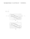
[0023] FIG. 5 is a process flow chart illustrating a transverse sectional plane by process in a method for manufacturing a hollow hydroformed product using a multi-tube assembly according to an embodiment of the present invention.
BEST MODE FOR CARRYING OUT THE INVENTION
[0024] Now, preferred embodiments of the present invention will be described in detail with reference to the accompanying drawings. The matters defined in the description, such as the detailed construction and elements, are nothing but specific details provided to assist those of ordinary skill in the art in a comprehensive understanding of the invention, and the present invention is not limited to the embodiments disclosed hereinafter.
[0025] FIG. 2 is a block diagrammatic flow chart illustrating a method for manufacturing a hollow hydroformed product using a multi-tube assembly according to an embodiment of the present invention, FIG. 3 illustrates the transverse and longitudinal cross-sectional views of modifications of a multi-tube assembly according to the present invention, and FIGS. 4 and 5 are process flow charts illustrating longitudinal and transverse sectional planes by process in a method for manufacturing a hollow hydroformed product using a multi-tube assembly according to an embodiment of the present invention.
[0026] A method S100 for manufacturing a hollow hydroformed product using a multi-tube assembly according to an embodiment of the present invention includes: (a) loading a multi-tube assembly 100 including inner and outer tubes 200 and 300 into a die D (S10); (b) injecting fluid F into the multi-tube assembly 100 (S20); (c) applying a hydraulic pressure of the fluid to the inner periphery of the outer tube 200 (S30); and (d) subjecting the outer tube 200 to plastic deformation to obtain a finally formed product (S40).
[0027] In step (a) (S10), the multi-tube assembly 100 including a hollow outer tube 200 and a hollow inner tube 300 inserted into the hollow outer tube is loaded into the die D consisting of an upper die U and a lower die L, each of which has a cavity C defined therein. In this case, the hollow inner tube 200 has a plurality of fluid channel holes 310 radially formed on the inner peripheral surface thereof. The inner and outer tubes 200 and 300 constituting the multi-tube assembly 100 may be made of the same material, but may is made of heterogeneous materials. In addition, the inner tube 300 may be implemented as a multi-layered tube configured such that at least two hollow tubes are inserted into the outer tube, each of the hollow tubes having a plurality of flow channel holes formed thereon so as to fluidically communicate each other.
[0028] In step (b) (S20), the fluid F is injected into the inner tube 300 so as to be supplied to the inner periphery of the inner tube 300.
[0029] In step (c) (S30), a hydraulic pressure of the fluid is applied to the inner periphery of the outer tube while the fluid F flows out of the inner tube 300 through the fluid channel holes 310 of the inner tube 300.
[0030] If the inner tube 300 is implemented as a multi-layered tube configured such that two hollow tubes 320 and 340 are inserted into the outer tube, the hollow tubes 320 and 340 have a plurality of flow channel holes 322 and 342 formed thereon, respectively, so as to fluidically communicate each other so that the fluid F can smoothly flow out of the inner tube 300 toward the outer tube 200.
[0031] In step (d) (S40), the outer tube 200 is subjected to bulging and plastic deformation to obtain a finally formed product having a desired outer peripheral shape.
[0032] Thus, in the production of a hollow part having the combined physical properties through the combination of materials, the inner periphery of the outer tube 300 is pressurized with fluid F while the fluid F flows out of the inner tube 300 (320 and 340) through the flow channel holes 310 (322 and 342) formed on the inner tube 300 (320 and 340), and then the outer tube 200 is subjected to the plastic deformation to thereby obtain a formed product having a desired outer peripheral shape. Resultantly, a hollow multi-tubular part can be fabricated irrespective of formability of the inner tube, and shaping precision can be greatly improved.
[0033] In the method S100 for manufacturing a hollow hydroformed product using a multi-tube assembly according to an embodiment of the present invention, the flow rate of the fluid F injected into the inner tube 300 (320 and 340) in step (b) (S20) is maintained to be equal to that of the fluid F flowing out of the inner tube through the fluid channel holes 310 (322 and 342) of the inner tube 300 (320 and 340) in step (c) (S30), or is determined within a range in which a pressure difference caused by a difference in the flow rate of the fluid supplied to the inner periphery and the outer periphery of the inner tube 300 (320 and 340) is less than a yield stress of the inner tube 300 (320 and 340) so that only the outer tube 200 is subjected to the plastic deformation.
[0034] Referring to FIGS. 4 and 5, the fluid F injected into the inner tube 300 (320 and 340) flows out of the inner tube 300 (320 and 340) and is supplied to the inner periphery of the outer tube 200 through the flow channel holes 310 (322 and 342). In this time, a hydraulic pressure is generated on the inner and outer peripheries of the inner tube 300 (320 and 340) due to the fluid F. If a pressure difference is caused by a difference in the flow rate of the fluid supplied to the inner periphery and the outer periphery of the inner tube, there may occur defects such as wrinkles created around the flow channel holes of the inner tube. Thus, in the present invention, the flow rate of the fluid F injected into the inner tube 300 (320 and 340) is caused to be maintained to be equal to that of the fluid F flowing out of the inner tube through the fluid channel holes 310 (322 and 342) of the inner tube 300 (320 and 340) so that the hydraulic pressures applied to the inner and outer peripheries of the inner tube 300 (320 and 340) can be equal to each other. Alternatively, although there is a difference in the flow rate of the fluid supplied to the inner periphery and the outer periphery of the inner tube 300 (320 and 340), the flow rate of the fluid F injected into the inner tube 300 (320 and 340) is caused to be maintained within a range of the flow rate in which a pressure difference caused by the difference in the flow rate is less than the yield stress of the inner tube 300 (320 and 340) so that a hydraulic pressure necessary for tube hydroforming can be applied to only the outer tube 200 without any deformation of the inner tube 300 (320 and 340). Herein, the flow rate of the fluid F to be injected to the inner tube 300 (320 and 340) can be calculated based on the cross-sectional area of the inner tube and the number and cross-sectional area of the flow channel holes.
[0035] Therefore, only the outer tube 200 is selectively plastic-deformed so that a hollow part having a desired outer shape can be fabricated without a change in the shape of the inner tube 300 (320 and 340).
[0036] As described above, the method 5100 for manufacturing a hollow hydroformed product using a multi-tube assembly according to the present invention has distinct advantages in that the inner periphery of the outer tube 200 is pressurized to hydroform the tubes by allowing fluid F to flow out of the inner tube 300 (320 and 340) through the flow channel holes 310 (322 and 342) formed on the inner tube 300 (320 and 340) of the multi-tube assembly 100 so that a hollow multi-tubular part can be fabricated regardless of formability of the inner tube 300 (320 and 340) and shaping precision can be greatly improved, and in that only the outer tube 200 is selectively plastic-deformed without any deformation of the inner tube 300 (320 and 340) so that a hollow part having a desired shape can be fabricated.
Mode for Invention
[0037] The method for manufacturing a hollow hydroformed product using a multi-tube assembly according to the present invention includes the steps of: (a) loading a multi-tube assembly into a die, the multi-tube assembly including a hollow outer tube and a hollow inner tube inserted into the hollow outer tube, the hollow inner tube having a plurality of fluid channel holes radially formed on the inner peripheral surface thereof; (b) injecting fluid into the inner tube so as to be supplied to the inner periphery of the inner tube; (c) applying a hydraulic pressure of the fluid to the inner periphery of the outer tube while the fluid flows out of the inner tube through the fluid channel holes of the inner tube; and (d) subjecting the outer tube to bulging and plastic deformation to obtain a finally formed product having a desired outer peripheral shape.
[0038] In addition, the inner tube may be implemented as a multi-layered tube configured such that at least two hollow tubes are inserted into the outer tube, each of the hollow tubes having a plurality of flow channel holes formed thereon so as to fluidically communicate each other.
[0039] Also, the outer tube and the inner tube may be made of heterogeneous materials.
[0040] In addition, preferably, the flow rate of the fluid injected into the inner tube in step (b) may be maintained to be equal to that of the fluid flowing out of the inner tube through the fluid channel holes of the inner tube in step (c) so that only the outer tube is plastic-deformed.
[0041] In addition, the flow rate of the fluid injected into the inner tube in step (b) may be determined within a range in which a pressure difference caused by a difference in the flow rate of the fluid supplied to the inner periphery and the outer periphery of the inner tube is less than a yield stress of the inner tube so that only the outer tube is plastic-deformed.
INDUSTRIAL APPLICABILITY
[0042] According to the present invention, a hollow multi-tubular part can be fabricated irrespective of formability of an inner tube, shaping precision can be greatly improved, and a hollow part having a desired shape can be fabricated without any deformation of the inner tube. Therefore, the present invention is expected to have a great effect on the industrial sector.
User Contributions:
Comment about this patent or add new information about this topic:
Images included with this patent application:
 |  |
 |  |
 |
| Similar patent applications: | |
| Date | Title |
|---|---|
| 2016-03-24 | Pump housing, in block form, of a vehicle brake system, and method for producing the same |
| 2016-02-18 | Die module set for pressing tools for producing screws |
| 2016-03-31 | Method and device for producing rotationally symmetrical metal components |
| 2016-03-17 | Roller hemming processing device and roller hemming processing method |
| 2016-03-03 | Apparatus and method for manufacturing a knuckle bracket |
| New patent applications in this class: | |
| Date | Title |
|---|---|
| 2016-04-14 | Method and device for producing a shaped component |
| 2014-12-11 | Rotor end band |
| 2014-09-18 | Pressure sequence process for hydro-forming an extruded structural tube |
| 2014-07-17 | Method for making metal body and metal box by using hydroforming |
| 2014-05-15 | Apparatus and method of forming reclosable containers |
| Top Inventors for class "Metal deforming" | |
| Rank | Inventor's name |
|---|---|
| 1 | Sergey Fedorovich Golovashchenko |
| 2 | Joel T. Pyper |
| 3 | Scott M. Breen |
| 4 | Thomas Flehmig |
| 5 | Matthias Kipping |