Patent application title: SUBSTRATE PROCESSING METHOD
Inventors:
Ryuya Koizumi (Tokyo, JP)
IPC8 Class: AC25D1716FI
USPC Class:
205 82
Class name: Electrolytic coating (process, composition and method of preparing composition) involving measuring, analyzing, or testing controlling coating process in response to measured or detected parameter
Publication date: 2015-10-29
Patent application number: 20150308010
Abstract:
A substrate processing method which can improve a throughput by
simultaneously processing various types of substrates is disclosed. The
substrate processing method includes: dividing substrate holders into a
first group and a second group; assigning each one of the substrate
holders to either a first recipe or a second recipe; calculating a total
transporting time in each of all possible transporting orders of
transporting substrates and the substrate holders for performing a first
process according to the first recipe and a second process according to
the second recipe; determining a transporting order that provides a
shortest total transporting time; and performing the first process on one
or a plurality of substrates using substrate holders belonging to the
first group and performing the second process on one or a plurality of
substrates using substrate holders belonging to the second group while
transporting the substrates according to the determined transporting
order.Claims:
1. A substrate processing method comprising: dividing substrate holders
into a first group and a second group; assigning each one of the
substrate holders to either a first recipe or a second recipe that
establishes substrate processing conditions; calculating a total
transporting time in each of all possible transporting orders of
transporting substrates and the substrate holders for performing a first
process according to the first recipe and a second process according to
the second recipe; determining a transporting order that provides a
shortest total transporting time; and performing the first process on one
or a plurality of substrates using substrate holders belonging to the
first group and performing the second process on one or a plurality of
substrates using substrate holders belonging to the second group while
transporting the substrates according to the determined transporting
order.
2. A substrate processing method comprising: dividing substrate holders into holder groups; dividing substrates into substrate groups according to processing purpose; assigning each one of the substrate groups to one of the holder groups; selecting a substrate holder for holding a substrate belonging to each substrate group from a holder group assigned to that substrate group; repeating the selecting of a substrate holder until the substrate holders are assigned to all of the substrates; performing a simulation of transporting the substrates and the substrate holders, while calculating a total transporting time from when processing of a first substrate is started to when processing of a final substrate is terminated; repeating the simulation and the calculating of a total transporting time while changing a transporting order of the substrates and the substrate holders; determining a transporting order that provides a shortest total transporting time; and transporting the substrates and the substrate holders according to the determined transporting order.
3. The substrate processing method according to claim 2, wherein dividing the substrates into the substrate groups according to processing purpose comprises dividing substrates into substrate groups according to a thickness of a substrate, a diameter of a substrate, or a shape of cutout portion formed in a substrate.
4. The substrate processing method according to claim 2, further comprising: simultaneously processing substrates with several different processing purposes in processing baths.
5. The substrate processing method according to claim 2, wherein: substrate numbers are assigned to the substrates; and the transporting order includes an order in which substrates belonging to a same holder group are transported in the order of increasing the substrate numbers.
Description:
CROSS REFERENCE TO RELATED APPLICATION
[0001] This document claims priority to Japanese Patent Application Number 2014-089383 filed Apr. 23, 2014, the entire contents of which are hereby incorporated by reference.
BACKGROUND
[0002] FIG. 14 is a view showing a substrate processing apparatus. As shown in FIG. 14, the substrate processing apparatus includes loading ports 100 on which substrate storage containers, each housing substrates (e.g., wafers) therein, are placed, a plurality of substrate holders 101 each for holding a substrate, a transporting device 102 for transporting a substrate holder 101 holding a substrate, and a plurality of processing baths 103 for processing a substrate. The substrate holders 101 are stored in a holder storage container 106. The transporting device 102 is operable to remove the substrate holder 101 from the holder storage container 106 and place it on a table 105. A transfer robot 104 removes a substrate from the substrate storage container on the loading port 100 and set the substrate on the substrate holder 101 that is placed on the table 105. The transporting device 102 transports the substrate holder 101, holding the substrate, to the processing baths 103, so that the substrate is processed in these processing baths 103.
[0003] An electrolytic plating apparatus is an example of the substrate processing apparatus. There are various kinds of substrates to be plated by the electrolytic plating apparatus. Examples of those substrates include a substrate on which a process of forming Through Silicon Via or TSV (hereinafter, this process will be referred to as TSV process) is to be performed, a substrate on which a process of farming bumps (hereinafter, this process will be referred to as bump process) is to be performed, a substrate on which a process of forming re-distribution layer or RDL (hereinafter, this process will be referred to as RDL process) is to be performed. In other words, in electrolytic plating, there are various purposes of processing substrates.
[0004] Substrates have various characteristics depending on the purpose of substrate processing or regardless of the purpose of substrate processing, The characteristics of a substrate include a thickness of the substrate, a bonding structure of substrates, a shape of cutout portion, such as a notch or an orientation flat, of the substrate, and an area where a seed layer or a resist is formed. A size (or diameter) of the substrate is also one of the characteristics of the substrate.
[0005] In some cases, one type of substrate holder cannot be used in processing of substrates having various characteristics, i.e., various types of substrates. Therefore, it is necessary to prepare various types of substrate holders having different structures in accordance with the characteristics of the substrates. In this specification, substrates of different types mean substrates that are required to use different types of substrate holders.
[0006] In order to maximize a processing performance, the substrate processing apparatus generally carries one type of many substrate holders and processes multiple substrates simultaneously. Accordingly, when different types of substrates are to be processed by one substrate processing apparatus, substrates of one type are firstly processed, and then an operation of the substrate processing apparatus is stopped, so that the substrate holders in the apparatus are replaced with substrate holders for another type of substrate. After the replacement of the substrate holders, a process of another type of substrates is started. In this manner, since the different types of substrates cannot be simultaneously processed by one substrate processing apparatus, a throughput of the substrate processing apparatus is lowered. Specifically, in a case of manufacturing wide variety of products in small quantities, the throughput is markedly lowered.
SUMMARY OF THE INVENTION
[0007] According to an embodiment, there is provided a substrate processing method which can improve a throughput by simultaneously processing various types of substrates.
[0008] Embodiments, which will be described below, relate to a substrate processing method which transports substrates to a plurality of processing baths to process the substrates, and more particularly to a substrate processing method capable of determining an order of transporting substrates by performing a substrate transporting simulation.
[0009] In an embodiment, there is provided a substrate processing method comprising: dividing substrate holders into a first group and a second group; assigning each one of the substrate holders to either a first recipe or a second recipe that establishes substrate processing conditions; calculating a total transporting time in each of all possible transporting orders of transporting substrates and the substrate holders for performing a first process according to the first recipe and a second process according to the second recipe; determining a transporting order that provides a shortest total transporting time; and performing the first process on one or a plurality of substrates using substrate holders belonging to the first group and performing the second process on one or a plurality of substrates using substrate holders belonging to the second group while transporting the substrates according to the determined transporting order.
[0010] In an embodiment, there is provided a substrate processing method comprising: dividing substrate holders into holder groups; dividing substrates into substrate groups according to processing purpose; assigning each one of the substrate groups to one of the holder groups; selecting a substrate holder for holding a substrate belonging to each substrate group from a holder group assigned to that substrate group; repeating the selecting of a substrate holder until the substrate holders are assigned to all of the substrates; performing a simulation of transporting the substrates and the substrate holders, while calculating a total transporting time from when processing of a first substrate is started to when processing of a final substrate is terminated; repeating the simulation and the calculating of a total transporting time while changing a transporting order of the substrates and the substrate holders; determining a transporting order that provides a shortest total transporting time; and transporting the substrates and the substrate holders according to the determined transporting order.
[0011] In an embodiment, dividing the substrates into the substrate groups according to processing purpose comprises dividing substrates into substrate groups according to a thickness of a substrate, a diameter of a substrate, or a shape of cutout portion formed in a substrate.
[0012] In an embodiment, the substrate processing method further comprises simultaneously processing substrates with several different processing purposes in processing baths.
[0013] In an embodiment, substrate numbers are assigned to the substrates, and the transporting order includes an order in which substrates belonging to a same holder group are transported in the order of increasing the substrate numbers.
[0014] According to the substrate processing method as described above, the simulation of transporting the substrates and the substrate holders is performed to determine an optimized transporting order. In this optimized transporting order, all of the substrate holders can be used efficiently. As a result, different types of substrates are simultaneously processed in the processing baths. Therefore, a throughput of the substrate processing can be improved.
BRIEF DESCRIPTION OF THE DRAWINGS
[0015] FIG. 1 is a plan view showing a substrate processing apparatus according to an embodiment;
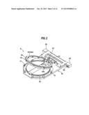
[0016] FIG. 2 is a perspective view of a substrate holder;
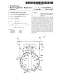
[0017] FIG. 3 is a plan view of the substrate holder;
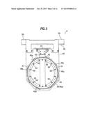
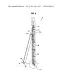
[0018] FIG. 4 is a side view of the substrate holder;
[0019] FIG. 5 is an enlarged view of a part indicated by symbol A shown in FIG. 4;
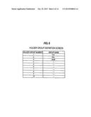
[0020] FIG. 6 is a diagram showing a holder group definition screen for registering holder group numbers and group names of substrate holders;
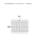
[0021] FIG. 7 is a schematic view showing substrate holders stored in respective slots of a holder storage container;
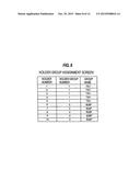
[0022] FIG. 8 is a diagram showing a holder group assignment screen for assigning a holder group number to each of the substrate holders (i.e., each of holder numbers);
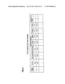
[0023] FIG. 9 is a diagram showing a total recipe setting screen;
[0024] FIG. 10 is a table showing the substrates divided into a plurality of substrate groups;
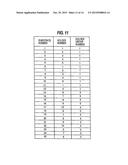
[0025] FIG. 11 is a table showing an example of the substrate holders assigned to the substrates;
[0026] FIG. 12 is a diagram showing a transportation simulation performed in accordance with an example of a transporting order;
[0027] FIG. 13 is a diagram showing a transportation simulation performed in accordance with another example of the transporting order; and
[0028] FIG. 14 is a view showing a substrate processing apparatus.
DESCRIPTION OF EMBODIMENTS
[0029] Embodiments will be described below with reference to the drawings. In FIGS. 1 through 13, identical or corresponding components will be denoted by identical reference numerals, and repetitive descriptions thereof are omitted.
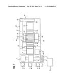
[0030] FIG. 1 is a plan view showing a substrate processing apparatus according to an embodiment. The substrate processing apparatus according to the embodiment is an electrolytic plating apparatus configured to plate a surface of a substrate with metal by passing electric current through a plating solution. However, the substrate processing apparatus is not limited to the electrolytic plating apparatus. For example, the substrate processing apparatus may be an electroless plating apparatus configured to plate a surface of a substrate with metal without passing electric current through a plating solution.
[0031] As shown in FIG. 1, the substrate processing apparatus includes loading ports 2 on which substrate cassettes (i.e., substrate storage containers), each carrying substrates W therein, are placed, and an aligner 4 for aligning an orientation flat or a notch of a substrate W in a predetermined direction. Further, the substrate processing apparatus includes a spin-rinse-dryer (SRD) 5 for drying a processed substrate W by rotating it at a high speed, a table 7 on which a substrate holder 6 (see FIGS. 2 through 5) is placed, and a substrate-holder opening and closing mechanism 11 for opening and closing the substrate holder 6 placed on the table 7. The substrate-holder opening and closing mechanism 11 is located above the table 7. A substrate-holder tilting mechanism 12 for raising and laying the substrate holder 6 is disposed above the table 7. The substrate-holder tilting mechanism 12 is configured to change the substrate holder 6 from a vertical position to a horizontal position and place the substrate holder 6 on the table 7.
[0032] A moving mechanism 9 extends along an arrangement direction of the load ports 2, and a substrate transfer robot 8 is mounted to the moving mechanism 9. The substrate transfer robot 8 is configured to move on the moving mechanism 9 and access the load ports 2, the substrate-holder opening and closing mechanism 11, and the aligner 4.
[0033] The substrate processing apparatus includes a holder storage container 13 for storing substrate holders 6 therein, a pre-cleaning bath 14 for cleaning a substrate W, held by a substrate holder 6, with a cleaning liquid, such as pure water, and a pretreatment bath 17 for pretreating the substrate W with a pretreatment liquid. Further, the substrate processing apparatus includes a plurality of plating baths 15 (ten plating baths 15 in this embodiment) each stores a plating solution (or a processing liquid) therein for plating the substrate W, a rinsing bath 18 for rinsing the plated substrate W with a rinsing liquid, and a blow bath 16 for removing the rinsing liquid from the substrate W. The blow bath 16 is configured to create air flow blowing the substrate W, held by the substrate holder 6, to thereby remove droplets remaining on the surface of the substrate W and to dry the substrate W.
[0034] Overflow baths 25 are disposed adjacent to the plating baths 15. The plating solution overflows the plating baths 15 into the overflow baths 25, and is returned to the plating baths 15 through circulation lines (not shown). A paddle motor unit 26 for driving a paddle (not shown) for agitating the plating solution in each plating bath 15 is disposed on one side of the plating baths 15. An exhaust duct 27 is disposed on the other side of the plating baths 15.
[0035] Next, the substrate holder 6 will be described with reference to FIGS. 2 through 5. As shown in FIGS. 2 through 5, the substrate holder 6 includes a first bolding member 40 having a rectangular plate shape and a second holding member 42 rotatably coupled to the first holding member 40 through a hinge 41. Although the second holding member 42 is configured to be openable and closable through the hinge 41 in this embodiment, it is also possible to dispose the second holding member 42 opposite to the first holding member 40 and to move the second holding member 42 away from and toward the first holding member 40 to thereby open and close the second holding member 42.
[0036] The first holding member 40 may be made of vinyl chloride. The second holding member 42 includes a base portion 43 and a ring-shaped seal holder 44. The seal holder 44 may be made of vinyl chloride. An annular substrate-side scaling member 46 (see FIG. 4 and FIG. 5), which projects inwardly, is attached to an upper portion of the seal holder 44. This substrate-side sealing member 46 is placed in pressure contact with a periphery of as surface of the substrate W to seal a gap between the second holding member 42 and the substrate W when the substrate W is held by the substrate holder 6. An annular holder-side sealing member 47 (see FIG. 4 and FIG. 5) is attached to a surface, facing the first holding member 40, of the seal holder 44. This holder-side scaling member 47 is placed in pressure contact with the first holding member 40 to seal a gap between the first holding member 40 and the second holding member 42 when the substrate W is held by the substrate holder 6. The holder-side sealing member 47 is located outside the substrate-side sealing member 46.
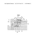
[0037] As shown in FIG. 5, the substrate-side sealing member 46 is sandwiched between the seal holder 44 and a first mounting ring 48a, which is secured to the seal holder 44 by fastening tools 49a, such as screws. The holder-side sealing member 47 is sandwiched between the seal holder 44 and a second mounting ring 48b, which is secured to the seal holder 44 by fastening tools 49b, such as screws.
[0038] The seal holder 44 has a stepped portion at a periphery thereof, and the retaining ring 45 is rotatably mounted to the stepped portion through a spacer 50. The retaining ring 45 is inescapably held by an outer peripheral portion of the first mounting ring 48a. This retaining ring 45 is made of a material (e.g., titanium) having high rigidity and excellent acid and alkali corrosion resistance. The spacer 50 is made of a material having a low friction coefficient, for example PTFE, so that the retaining ring 45 can rotate smoothly.
[0039] Inverted L-shaped clampers 51, each having an inwardly projecting portion and located at the outer side of the retaining ring 45, are secured to the first bolding member 40 at equal intervals along a circumferential direction of the retaining ring 45. The retaining ring 45 has, on its outer circumferential surface, outwardly projecting portions 45b arranged at positions corresponding to positions of the clampers 51. A lower surface of the inwardly projecting portion of each clamper 51 and an upper surface of each projecting portion 45b of the retaining ring 45 are inclined in opposite directions along the rotational direction of the retaining ring 45 to form inclined surfaces. A plurality (e.g., three) of upwardly projecting protrusions 45a are provided on the retaining ring 45 at predetermined locations along the circumferential direction of the retaining ring 45, The retaining ring 45 can be rotated by pushing and moving each protrusion 45a in a lateral direction by means of a rotating pin (not shown).
[0040] With the second holding member 42 open, the substrate W is inserted into the central portion of the first holding member 40, and the second holding member 42 is then closed through the hinge 41. Subsequently the retaining ring 45 is rotated clockwise so that each projecting portion 45b of the retaining ring 45 slides into the inwardly projecting portion of each clamper 51. As a result, the first holding member 40 and the second holding member 42 are fastened to each other and locked by engagement between the inclined surfaces of the retaining ring 45 and the inclined surfaces of the clampers 51. The second holding member 42 can be unlocked by rotating the retaining ring 45 counterclockwise to disengage the projecting portions 45b of the retaining ring 45 from the clampers 51.
[0041] When the second holding member 42 is fastened to the first holding member 40, a downwardly-protruding portion of the substrate-side sealing member 46 is placed in pressure contact with the periphery of the surface of the substrate W. The substrate-side sealing member 46 is pressed uniformly against the substrate W to thereby seal the gap between the periphery of the surface of the substrate W and the second holding member 42. Similarly, when the second holding member 42 is fastened to the first holding member 40, a downwardly-protruding portion of the holder-side scaling member 47 is placed in pressure contact with the surface of the first holding member 40. The sealing holder-side sealing member 47 is uniformly pressed against the first holding member 40 to thereby seal the gap between the first holding member 40 and the second holding member 42.
[0042] A ring-shaped protruding portion 52, which is in a ring shape corresponding to a size of the substrate W, is formed on an upper surface of the first holding member 40. This protruding portion 52 has an annular support surface 53 which comes in contact with the periphery of the substrate W to support the substrate W. The protruding portion 52 has recesses 54 located at predetermined positions along a circumferential direction of the protruding portion 52.
[0043] As shown in FIG. 3, a pair of holder hangers 59 are provided on an end portion of the first holding member 40. A plurality of outer contacts 60 are provided on one of the two holder hangers 59. The holder hungers 59 are placed onto surround walls of the pre-cleaning bath 14, the pretreatment bath 17, the plating baths 15, the rinsing bath 18, and the blow bath 16 so that the substrate holder 6 is suspended from these surround walls.
[0044] As shown in FIG. 5, the substrate holder 6 further includes a plurality of inner contacts 55 to be brought into contact with the peripheral portion of the substrate W to pass the electric current to the substrate W. Each inner contact 55 includes a conductive member 56 and a contact member 57. The contact member 57 is located so as to be brought into contact with the conductive member 56 and the peripheral portion of the substrate W. As shown in FIG. 3, the plural conductive members 56 (e.g., twelve conductive members 56 as illustrated) are secured to the recesses 54, respectively. The conductive members 56 are connected to a plurality of wires extending from the outer contacts 60, respectively. The conductive members 56 are mounted to the first holding member 40, and the contact members 57 are secured to the seal holder 44 of the second holding member 42 by fastening tools 58, such as screws. Therefore, when the second holding member 42 is opened, the contact members 57 are away from the conductive members 56. When the second holding member 42 is closed with the substrate W placed on the support surface 53 of the first holding members 40, the contact members 57 elastically make contact with distal ends of the conductive member 56, respectively, as shown in FIG. 5. The number of contact members 57 (twelve contact members 57 in this embodiment) is the same as the number of conductive members 56.
[0045] The contact members 57 each have a leaf spring-like contact portion located outside the substrate-side sealing member 46 and projecting inwardly. The contact member 57 is springy and bends easily. When the substrate W is held by the first holding member 40 and the second holding member 42, contact portions of the contact members 57 make elastic contact with the peripheral portion of the substrate W supported on the support surface 53 of the first holding member 40, while lower portions of the contact members 57 make contact with the conductive members 56.
[0046] The second holding member 42 is opened and closed by a not-shown pneumatic cylinder and by a weight of the second holding member 42. More specifically, the first holding member 40 has a through-hole 40a, and the pneumatic cylinder (not shown) is disposed at a position opposite to the through-hole 40a when the substrate holder 6 is placed on the table 7. The second holding member 42 is opened by extending a piston rod of the pneumatic cylinder through the through-hole 40a to push up the seal holder 44 of the second holding member 42. The second holding member 42 is closed by its own weight when the piston rod is retracted.
[0047] As shown in FIG. 1, the substrate processing apparatus includes a transporter (i.e., transporting device) 20 for transporting substrate holders 6, each holding a substrate W, one by one between the holder storage container 13, the pre-cleaning bath 14, the pretreatment bath 17, the plating baths 15, the rinsing bath 18, the blow bath 16, and the substrate-holder opening and closing mechanism 11. Hereinafter, the pre-cleaning bath 14, the pretreatment bath 17, the plating baths 15, the rinsing bath 18, and the blow bath 16 will be collectively referred to as processing baths for processing a substrate.
[0048] The transporter 20 includes a fixed base 21 extending along an arrangement direction of the processing baths and the holder storage container 13, a lifter 22 configured to be horizontally movable on the fixed base 21, and an arm 23 coupled to the lifter 22. The arm 23 has a gripper 24 for gripping the substrate holder 6. The arm 23 and the lifter 22 horizontally move together, and the arm 23 is elevated and lowered by the lifter 22, A linear motor or a rack and pinion may be used as a driving device for horizontally moving the lifter 22 and the arm 23.
[0049] The substrate processing apparatus includes a controller 3 for controlling operations of the apparatus, and a transporting order determiner 65 for determining an order of processing the substrates W in the processing baths (i.e., a transporting order of the substrates W). The transporting order determiner 65 is coupled to the controller 3 so that signal representing art order, determined by the transporting order determiner 65, is sent to the controller 3. The controller 3 is configured to control operations of the substrate transfer robot 8 and the transporter 20 so that the substrates W are transported in the determined order. The controller 3 is configured to obtain data showing operational states of the processing baths and send the data to the transporting order determiner 65.
[0050] The controller 3 includes an input section 66 having entry screens and an input device (e.g., a keyboard or input buttons). An operator enters data, which are required for determining the order of transporting the substrates, into the controller 3 using the input section 66. The entry screens will be described below.
[0051] FIG. 6 is a view showing a holder group definition screen for registering holder group numbers and group names of the substrate holders 6. In the embodiment shown in FIG. 6, TSV, RDL, and bump are used as the group names. The substrates, on which the TSV process, the RDL process, and the bump process are to be performed, have different Characteristics. In FIG. 6, a holder group number 1 is assigned to the TSV process, a holder group number 2 is assigned to the RDL process, and a holder group number 3 is assigned to the bump process. In this manner, the holder group numbers are defined according to the purpose of processing the substrate.
[0052] FIG. 7 is a schematic view showing the multiple substrate holders 6 stored in respective slots 13a of the holder storage container 13. As shown in FIG. 7, holder numbers 1 to 10 are assigned to the substrate holders 6, respectively. Each holder number is a number indicating which of the slots 13a each substrate holder 6 is stored.
[0053] FIG. 8 is a diagram showing a holder group assignment screen for assigning the holder group number to each of the substrate holders 6 (i.e., each of the holder numbers). The transporter 20 carries the substrate holders 6 of several different types into the slots 13a of the holder storage container 13 according to a command of the operator. The operator may directly carry the substrate holders 6 into the slots 13a, respectively. In the embodiment shown in FIG. 8, two types of substrate holders 6 are prepared and set in the slots 13a of the holder storage container 13 according to the purpose of processing the substrates.
[0054] The holder group assignment screen is used to enable the apparatus to recognize the substrate holders 6 belonging to the same holder group, i.e., the substrate holders 6 that can be used for the same processing purpose. For example, as shown in FIG. 8, the substrate holders 6 are classified into two groups, i.e., a holder group 1 and a holder group 3, according to the purpose of processing the substrate. The substrate holders 6 with the holder numbers 1 to 5 belong to the holder group 1, and the substrate holder 6 with the holder numbers 6 to 10 belong to the holder group 3. The substrate holders 6 with the holder numbers 1 to 5 belonging to the holder group 1 are registered as substrate holders for use in the TSV process. The substrate holders 6 with the holder numbers 6 to 10 belonging to the holder group 3 are registered as substrate holders for use in the bump processing.
[0055] In the above-described embodiment, the types of substrate holders 6 that are set in the holder storage container 13 should correspond to the holder group numbers that have been registered through the holder group assignment screen. However, the operator may possibly make an input error. Thus, a common identification mark may be attached in advance to the substrate holders 6 of the same type so that the identification mark can be detected by an identification mark detector (not shown), such as an optical sensor, disposed on the transporter 20 or the holder storage container 13. The identification mark detector is electrically connected to the controller 3, and is configured to send the detected identification mark to the controller 3.
[0056] The controller 3 can automatically enter the holder numbers and the holder group numbers into the holder group assignment screen according to the detected identification marks. The operator may manually enter the holder numbers and the holder group numbers into the holder group assignment screen. In that case, the identification marks may be then detected by the identification mark detector. There may be a case where a result of the manual entry does not correspond to a result of automatic entry. In such a case, the controller 3 may emit an error message. Data entered in the holder group assignment screen are transmitted to the transporting order determiner 65.
[0057] FIG. 9 is a diagram showing a total recipe setting screen. A total recipe includes recipe number, recipe ID, and items representing a content of unit recipe. The unit recipe is a recipe that establishes substrate processing conditions (e.g., a processing time, flow rate of the processing liquid, etc.) in each of the units, i.e., the pre-cleaning bath 14, the pretreatment bath 17, the plating baths 15, the rinsing bath 18, the blow bath 16, and the spin-rinse-dryer (SRD) 5. The controller 3 includes a storage device 70 (see FIG. 1) for storing unit recipes that have been created in advance. The storage device 70 stores therein the unit recipes as shown in FIG. 9.
[0058] The operator selects unit recipe required for accomplishing the processing purpose from the unit recipes, and creates total recipes with use of the total recipe setting screen. Further, the operator assigns the holder group numbers to the total recipes, respectively. The substrate holders 6 to be used for processing the respective substrates W are determined by this assigning operation, Data entered in the total recipe setting screen (i.e., the selected unit recipes and the holder group numbers assigned to the total recipes) are transmitted to the transporting order determiner 65. In FIG. 9, a recipe ID "ABC" is assigned to a recipe number 1, and a recipe ID "DEF" is assigned to a recipe number 2. The total recipe represents specific processing conditions for accomplishing the purpose of processing the substrate W.
[0059] The holder group number 1 is assigned to the recipe number 1, and the holder group number 3 is assigned to the recipe number 2. Therefore, the recipe number 1 represents a total recipe for forming TSV on a substrate W, and the recipe number 3 represents a total recipe for forming bumps on a substrate W. As can be seen from FIG. 9, a substrate W is processed through the pre-cleaning operation, the pretreatment operation, the plating operation, the rinsing operation, the blowing operation, and the drying operation.
[0060] FIG. 10 is a table showing plural substrates W divided into a plurality of substrate groups. Substrate numbers 1 to 25 represent the substrates W carried in the substrate cassette. The substrates W (twenty-five substrates in the embodiment) are carried in the substrate cassette.
[0061] Since the substrate cassette carries the twenty-five substrates therein in this embodiment, the substrate numbers 1 to 25 are assigned to the twenty-five substrates W, respectively. The number of substrates W in the substrate cassette is counted by the operator. The operator enters the number of substrates W into the controller 3 through the input section 66. The controller 3 sends the entered number of substrates W to the transporting order determiner 65. The number of substrates W in the substrate cassette may be automatically counted by a substrate detector (not shown), such as an optical sensor connected to the controller 3. The substrate detector may be disposed adjacent to the substrate cassette and may emit a light beam toward the substrates W to count the number of substrates W. The number of substrates W may be sent from the substrate detector to the controller 3 and may be sent from the controller 3 to the transporting order determiner 65.
[0062] The operator divides the substrates W into the substrate groups according to the purpose of processing the substrate W (i.e., the characteristic of the substrate W) with use of the input section 66. In the embodiment shown in FIG. 10, the substrates W with the substrate numbers 1 to 25 are divided into a substrate group 1 consisting of substrate numbers 1 to 12 and a substrate group 2 consisting of substrate numbers 13 to 25. The recipe number 1 and the holder group number I are assigned to the substrate group 1. This means that the process of forming TSV in the substrate W using the total recipe identified by the recipe number 1 is applied to the substrates W with the substrate numbers 1 to 12, and that the substrate holders 6 belonging to the holder group number 1 are used in the process of the substrates W with the substrate numbers 1 to 12. The recipe number 2 and the holder group number 3 are assigned to the substrate group 2. This means that the process of forming bumps using the total recipe identified by the recipe number 2 is applied to the substrates W with the substrate numbers 13 to 25, and that the substrate holders 6 belonging to the holder group number 3 are used in the process of the substrate W with the substrate numbers 13 to 25.
[0063] The transporting order determiner 65 receives the data entered in the holder group assignment screen, the data entered in the total recipe setting screen, the number of substrates W in the substrate cassette, and the data of the operational states of the processing baths from the controller 3. The transporting order determiner 65 then determines a transporting order that can minimize a total transporting time which is from when processing of a first substrate is started to when processing of a final substrate is terminated. The process of determining of the transporting order will be described.
[0064] The transporting order determiner 65 assigns each one of the substrate groups to one of the holder groups. As shown in FIG. 8, the ten substrate holders 6 are divided into the holder group 1 and the holder group 3. Further, as shown in FIG. 10, the twenty-five substrates W are divided into the substrate group 1 and the substrate group 2. The transporting order determiner 65 assigns the substrate group 1 to the holder group 1 and assigns the substrate group 2 to the holder group 3.
[0065] Subsequently, the transporting order determiner 65 selects a substrate holder 6 to be used for holding a substrate W, belonging to each substrate group, from the holder group assigned to that substrate group. The transporting order determiner 65 repeats selecting of a substrate holder 6 until the substrate holders 6 are assigned to all of the substrates W.
[0066] FIG. 11 is a table showing an example of the substrate holders 6 assigned to the substrates. As shown in FIG. 11, the substrates W with the substrate numbers 1 to 12 are assigned to the holder group 1 consisting of the substrate holders 6 with the holder numbers 1 to 5. Therefore, the substrate holders for holding the substrates W with the substrate numbers 1 to 12 are selected from the corresponding holder group 1.
[0067] In the embodiment shown in FIG. 11, the substrate holders 6 with the holder numbers 1 to 5 are assigned to the substrates W with the substrate numbers 1 to 5, respectively. The substrate holders 6 with the holder numbers 1 to 5 are assigned to the substrates W with the substrate numbers 6 to 10, respectively. The substrate holders 6 with the holder numbers 1 to 2 are assigned to the substrates W with the substrate numbers 11 to 12, respectively. In this manner, one of the substrate holders 6 with the holder numbers 1 to 5 is assigned to each one of the substrates W with the substrate numbers 1 to 12.
[0068] Similarly, the substrate holders for holding the substrates W with the substrate numbers 13 to 25 are selected from the corresponding holder group 3. In the embodiment shown in FIG. 11, the substrate holders 6 with the holder numbers 6 to 10 are assigned to the substrates W with the substrate numbers 13 to 17, respectively, the substrate holders 6 with the holder numbers 6 to 10 are assigned to the substrates W with the substrate numbers 18 to 22, respectively, and the substrate holders 6 with the holder numbers 6 to 8 are assigned to the substrates W with the substrate numbers 23 to 25, respectively. In this manner, one of the substrate holders 6 with the holder numbers 6 to 10 is assigned to each of the substrates W with the substrate numbers 13 to 25.
[0069] The transporting order determiner 65 is configured to determine a transporting order that can minimize a total transporting time which is from when processing of a first substrate is started to when processing of a final substrate is terminated. The first substrate is one of the substrates W in the substrate cassette, and the final substrate is also one of the substrates W in the substrate cassette. The transporting order determiner 65 creates a possible transporting order for combinations consisting of the substrates W and the substrate holders 6, repeatedly performs a simulation of transporting the combinations while changing the transporting order, and calculates the total transporting time in each transporting order. The transporting order determiner 65 determines the transporting order that can provide the shortest total transporting time.
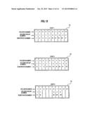
[0070] FIG. 12 is a diagram showing a transportation simulation performed according to an example of the transporting order (transporting order 1). In FIG. 12, as indicated by steps 1 through 5, the substrates W are transported in the order of the substrate numbers 1 to 25. As shown in FIG. 12, the substrate holders 6 with the holder numbers 1 to 10 are stored in the holder storage container 13. In step 1, the substrates W with the substrate numbers 1 to 5 and the substrate holders with the holder numbers 1 to 5 are successively transported. In step 2, the substrates \V with the substrate numbers 6 to 10 and the substrate holders 6 with the holder numbers 1 to 5 are successively transported. While the substrates W with the substrate numbers 1 to 10 and the substrate holders 6 with the holder numbers 1 to 5 are transported, the substrate holders 6 with the holder numbers 6 to 10 are not used.
[0071] In step 3, the substrates W with the substrate numbers 11 to 17 and the substrate holders 6 with the holder numbers 1 to 2, 6 to 10 are successively transported. In this step 3, the substrates W with different processing purposes, i.e., the substrates W different types, are successively transported to the processing baths. Subsequently, in step 4, the substrates W with the substrate numbers 18 to 22 and the substrate holders 6 with the holder numbers 6 to 10 are successively transported. In step 5, the substrates W with the substrate numbers 23 to 25 and the substrate holders 6 with the holder numbers 6 to 8 are successively transported. The transporting order determiner 65 performs the simulation of the transportation from the step 1 to the step 5, and calculates the total transporting time from when processing of the first substrate (the substrate W with the substrate number 1) is started to when processing of the final substrate (the substrate W with the substrate number 25) is terminated.
[0072] FIG. 13 is a diagram showing a transportation simulation performed according to another example of the transporting order (transporting order 2). In step 1, the substrates W with the substrate numbers 1 to 5, 13 to 17 and the substrate holders 6 with the holder numbers 1 to 10 are successively transported. in step 2, the substrates W with the substrate numbers 6 to 10, 18 to 22 and the substrate holders 6 with the holder numbers 1 to 10 are successively transported. In step 3, the substrates W with the substrate numbers 11 to 12, 23 to 25 and the substrate holders 6 with the holder numbers 1 to 2, 6 to 8 are successively transported. The transporting order determiner 65 performs the transportation simulation from the step 1 to the step 3, and calculates the total transporting time from when processing of the first substrate (the substrate W with the substrate number 1) is started to when processing of the final substrate (the substrate W with the substrate number 25) is terminated.
[0073] All of the substrates W are transported through five steps in the example shown in FIG. 12, while all of the substrates W are transported through three steps in the example shown in FIG. 13. The transporting order determiner 65 compares the total transporting time in the case of the transporting order 1 with the total transporting time in the case of the transporting order 2 to determine the transporting order that can provide the shortest total transporting time of the substrates W and the substrate holders 6. Since the total transporting time in the case of the transporting order 2 is shorter than the total transporting time in the case of the transporting order 1, the transporting order determiner 65 determines the transporting order 2 that results in the shortest total transporting time.
[0074] The transporting order determiner 65 creates all of possible transporting orders. In this regard, substrates belonging to the same holder group are transported in the order of increasing the substrate numbers. Any transporting order that does not meet this rule is eliminated. The transporting order determiner 65 performs the transportation simulation in accordance with all of the created transporting orders, calculates the total transporting time in each one of the created transporting orders, determines the transporting order that can provide the shortest total transporting time, and sends a signal representing the determined transporting order to the controller 3.
[0075] The controller 3 commands the transporter 20 to transport the substrates W and the substrate holders 6 according to the determined transporting order. Upon receiving the command, the transporter 20 transports the substrates W and the substrate holders 6 according to the determined transporting order, and the substrates W are processed in the above-described processing baths.
[0076] In the optimized transporting order, all of the substrate holders 6 can be used efficiently. In particular, as shown in FIG. 13, the substrates of different types are successively transported to the processing baths in all of the steps 1, 2, and 3 so that the substrates are processed simultaneously in these processing baths. Therefore, a throughput of the substrate processing can be improved.
[0077] The transporting order determiner 65 performs the total recipe identified by the recipe number 1 with use of the substrate holders 6 belonging to the holder group 1. In a case where all of the substrate holders 6 belonging to the holder group 1 are moved from the holder storage container 13, i.e., in a case where all of the substrate holders 6 belonging to the holder group 1 are used, the substrate holders 6 belonging to the holder group 3 may be used to perform the total recipe identified by the recipe number 2. With this transporting order, it is possible to process the substrates efficiently because the total recipe using the substrate holders 6 belonging to the holder group 3 can be performed without waiting for the termination of all processes of the total recipe using the holder group 1.
[0078] An executive instruction 1 for performing the total recipe identified by the recipe number 1 using the substrate holders 6 belonging to the holder group 1 and an executive instruction 2 for performing the total recipe identified by the recipe number 2 using the substrate holders 6 belonging to the holder group 3 may be registered in the controller 3. When the operator pushes an execution button provided in the input section 66 of the controller 3, the transporting order determiner 65 creates possible transporting orders from among the substrates W assigned to the substrate holders 6 registered in the executive instructions 1 and 2. Thereafter, the transporting order determiner 65 performs the transportation simulation according to all of the created transporting orders, calculates the total transporting time in each transporting order, and determines the transporting order that minimizes the total transporting time.
[0079] If the substrate processing based on the executive instruction 2 is performed after the substrate processing based on the executive instruction 1 is performed (i.e., if the operator pushes the execution button), the transporting order determiner 65 creates possible transporting orders from among remaining substrates W that have not been processed yet. The transporting order determiner 65 then performs the transportation simulation, and determines the transporting order that can minimize the total transporting time. This method of determining of the transporting order is called an interrupt processing.
[0080] While the present invention has been described with reference to the embodiments thereof, it should be noted that the present invention is not limited to the particular embodiments described above and can be applied to various other embodiments within the technical concept of the present invention. For example, while the above-described embodiments determine the transporting order that provides the shortest total transporting time for substrates carried in one substrate cassette, it is also possible to determine the transporting order that provides the shortest total transporting time for substrates carried in a plurality of substrate cassettes.
User Contributions:
Comment about this patent or add new information about this topic:
Images included with this patent application:
 |  |
 |  |
 |  |
 |  |
 |  |
 |  |
 |  |
 |
| New patent applications in this class: | |
| Date | Title |
|---|---|
| 2016-04-28 | Prevent and remove organics from reservoir wells |
| 2015-10-22 | Methods and apparatuses for electroplating nickel using sulfur-free nickel anodes |
| 2015-03-05 | Dynamic formation protocol for lithium-ion battery |
| 2015-02-12 | Apparatuses and methods for maintaining ph in nickel electroplating baths |
| 2014-06-19 | Sn alloy plating apparatus and method |
| New patent applications from these inventors: | |
| Date | Title |
|---|---|
| 2022-07-14 | Method for determining optimal number of submodules for use in semiconductor manufacturing apparatus including substrate processing module including plurality of submodules, and semiconductor manufacturing apparatus |
| 2021-01-14 | Scheduler, substrate processing apparatus, and substrate conveyance method |
| 2017-06-22 | Plating apparatus |
| 2014-09-04 | Plating apparatus |
| 2011-07-14 | Scheduler, substrate processing apparatus, and method of transferring substrates in substrate processing apparatus |
| Top Inventors for class "Electrolysis: processes, compositions used therein, and methods of preparing the compositions" | |
| Rank | Inventor's name |
|---|---|
| 1 | Benjamin J. Feldman |
| 2 | Adam Heller |
| 3 | Michael S. Lockard |
| 4 | Fei Mao |
| 5 | Joseph A. Vivolo |