Patent application title: Pitching Screen Assembly
Inventors:
Terry J. Kaper (Delta, OH, US)
IPC8 Class: AA63B6900FI
USPC Class:
473451
Class name: Playing field or court game; game element or accessory therefor other than projector or projectile, per se practice or training device for game in which play involves base running (e.g., for baseball, cricket, etc.)
Publication date: 2015-10-22
Patent application number: 20150297965
Abstract:
A pitching screen assembly adapted to be readily converted between a
non-deployed configuration and a deployed configuration including: first
and second ground-engaging support members each having first ends, second
ends, and midpoints, wherein the first and second ends define lengths
therebetween; a frame sub-assembly associated with the first and second
ground-engaging support members, wherein the frame sub-assembly includes
an internal aperture contained therein; a protective screen, wherein the
protective screen is displaceable within the frame sub-assembly between a
non-deployed position and a deployed position along a first axis (X); and
wherein when in the non-deployed position the internal aperture of the
frame sub-assembly remains substantially open to allow a pitcher to pitch
a ball with a normal throwing motion, and wherein when in the deployed
position the internal aperture of the frame sub-assembly is closed to
protect a pitcher from a batted ball.Claims:
1. A pitching screen assembly adapted to be readily converted between a
non-deployed configuration and a deployed configuration, comprising: a
first ground-engaging support member having a first end, a second end,
and a midpoint, wherein the first end and the second end define a length
therebetween; a second ground-engaging support member having a first end,
a second end, and a midpoint, wherein the first end and the second end
define a length therebetween; a frame sub-assembly associated with the
first and second ground-engaging support members, wherein the frame
sub-assembly includes an internal aperture contained therein; a
protective screen, wherein the protective screen is linearly displaceable
within the frame sub-assembly between a non-deployed position and a
deployed position along a first axis (X); and wherein when in the
non-deployed position the internal aperture of the frame sub-assembly
remains substantially open to allow a pitcher to pitch a ball with a
normal throwing motion, and wherein when in the deployed position the
internal aperture of the frame sub-assembly is closed to protect a
pitcher from a batted ball.
2. The pitching screen assembly according to claim 1, wherein the first axis (X) is generally orthogonal to the length of the first ground-engaging support member and the length of the second ground-engaging support member.
3. The pitching screen assembly according to claim 1, wherein the frame sub-assembly comprises a left frame member, a right frame member, a top frame member, and a bottom frame member.
4. The pitching screen assembly according to claim 3, wherein the top frame member of the frame sub-assembly includes a guide rail.
5. The pitching screen assembly according to claim 4, wherein the guide rail comprises a pair of channels for retaining guide wheels therein.
6. The pitching screen assembly according to claim 5, wherein the pair of channels include wheels that are connected via a rod.
7. The pitching screen assembly according to claim 6, wherein a portion of the protective screen is attached to the rod.
8. The pitching screen assembly according to claim 1, wherein a compression spring is associated with the top frame member of the frame sub-assembly.
9. The pitching screen assembly according to claim 8, wherein a releasable stop member regulates displacement of the protective screen.
10. The pitching screen assembly according to claim 1, wherein the frame sub-assembly is rotatably displaceable from an upright position to a non-upright position along the first axis (X).
11. The pitching screen assembly according to claim 10, further comprising a strike pad associated with the protective screen.
12. The pitching screen assembly according to claim 10, wherein the protective screen further comprises a handle member.
13. The pitching screen assembly according to claim 10, wherein the frame sub-assembly further comprises a handle member.
14. The pitching screen assembly according to claim 1, wherein the first end and the second end of the first ground-engaging support member each comprise an aperture for receiving a securement stake.
15. The pitching screen assembly according to claim 1, wherein the first end and the second end of the first ground-engaging support member and the first end and the second end of the second ground-engaging support member each comprise a pair of apertures for receiving a generally U-shaped securement stake.
16. The pitching screen assembly according to claim 1, further comprising a remote control sub-assembly which comprises a housing, an actuating mechanism, an energy source, a receiver, and a transmitter.
17. The pitching screen assembly according to claim 16, further comprising an inertia charger.
18. The pitching screen assembly according to claim 17, further comprising a rectifier.
19. A pitching screen assembly adapted to be readily converted between a non-deployed configuration and a deployed configuration, comprising: a first ground-engaging support member having a first end, a second end, and a midpoint, wherein the first end and the second end define a length therebetween; a second ground-engaging support member having a first end, a second end, and a midpoint, wherein the first end and the second end define a length therebetween; a frame sub-assembly associated with the first and second ground-engaging support members, wherein the frame sub-assembly includes an internal aperture contained therein, and wherein the frame sub-assembly is rotatably displaceable from an upright position to a non-upright position along a first axis (X); a protective screen, wherein the protective screen is linearly displaceable within the frame sub-assembly between a non-deployed position and a deployed position along the first axis (X); and wherein when in the non-deployed position the internal aperture of the frame sub-assembly remains substantially open to allow a pitcher to pitch a ball with a normal throwing motion, and wherein when in the deployed position the internal aperture of the frame sub-assembly is closed to protect a pitcher from a batted ball.
20. A pitching screen assembly adapted to be readily converted between a non-deployed configuration and a deployed configuration, comprising: a first ground-engaging support member having a first end, a second end, and a midpoint, wherein the first end and the second end define a length therebetween; a second ground-engaging support member having a first end, a second end, and a midpoint, wherein the first end and the second end define a length therebetween; a frame sub-assembly associated with the first and second ground-engaging support members, wherein the frame sub-assembly includes an internal aperture contained therein; a protective screen, wherein the protective screen is linearly displaceable within the frame sub-assembly between a non-deployed position and a deployed position along a first axis (X), wherein the first axis (X) is generally orthogonal to the length of the first ground-engaging support member and the length of the second ground-engaging support member; wherein when in the non-deployed position the internal aperture of the frame sub-assembly remains substantially open to allow a pitcher to pitch a ball with a normal throwing motion, and wherein when in the deployed position the internal aperture of the frame sub-assembly is closed to protect a pitcher from a batted ball; and a remote control sub-assembly which comprises a housing, an actuating mechanism, an energy source, a receiver, and a transmitter.
Description:
CROSS-REFERENCE TO RELATED APPLICATIONS
[0001] This application is a continuation-in-part of U.S. patent application Ser. No. 14/256,271, filed Apr. 18, 2014, entitled "Pitching Screen Assembly," which is hereby incorporated herein by reference in its entirety, including all references cited therein.
BACKGROUND OF THE INVENTION
[0002] 1. Field of the Invention
[0003] The present invention relates in general to a pitching screen assembly and, more particularly, to a pitching screen assembly that is linearly displaceable between a non-deployed position (e.g., when a pitcher is pitching a ball) and a deployed position (e.g., after the pitcher has pitched the ball) along a first axis (X) and vice versa. The pitching screen assembly is also optionally rotatably displaceable along the first axis (X).
[0004] 2. Background Art
[0005] Baseball, widely known as America's pastime, is now extremely popular in several other countries as well, including, for example, Canada, Cuba, Japan, and the Netherlands. While baseball has become extremely popular in several countries, sports headlines are now plagued with tragic stories of pitchers being struck by line drives, sometimes at over one hundred miles per hour, and suffering fractured skulls and closed-head injuries, including, but not limited to, concussions, intracranial hematomas, cerebral contusions, etcetera. These head injuries can result in lifelong physical, cognitive, and/or psychological impairment and, thus, are of utmost concern to those associated with baseball.
[0006] One proposed solution is to provide a padded or armored baseball hat, but thus far successfully dissipating the kinetic energy associated with a line drive with such a padded or armored baseball cap has been commercially unattainable and/or futile.
[0007] Another solution, at least for practice, slow-pitch softball, little league, amateur baseball, collegiate baseball, semi-professional baseball, and certain levels of professional baseball, is the utilization of pitching screen assemblies. Pitching screen assemblies have been known in the art for years and are the subject of numerous patents, including but not limited to: U.S. Pat. No. 8,388,471 entitled "Pitching Screen;" U.S. Pat. No. 6,955,615 entitled "Pitcher Screen;" U.S. Pat. No. 6,543,776 entitled "Foldable Net;" U.S. Pat. No. 5,690,339 entitled "Collapsible Sports Goal Apparatus;" U.S. Pat. No. 5,407,211 entitled "Compact Adjustable Portable Sports Practice Net;" U.S. Pat. No. 5,088,740 entitled "Practice Backstop For Ball Playing Sports;" U.S. Pat. No. 4,978,121 entitled "Portable Pitching Practice System;" U.S. Pat. No. 4,489,941 entitled "Sports Net Apparatus;" and United States Patent Application Publication Number 2013/0168334 entitled "Component Frame of a Pitching Screen"--all of which are hereby incorporated herein by reference in their entirety, including all references cited therein.
[0008] U.S. Pat. No. 8,388,471 appears to disclose a pitching screen which provides a first pitching lane and a second pitching lane in a single pitching screen configuration to allow both left-handed pitchers and right-handed pitchers to pitch without repositioning the pitching screen.
[0009] U.S. Pat. No. 6,955,615 appears to disclose a pitcher's screen comprising a lower screen having opposite ends and a base secured to the lower screen. An upper screen is pivotally connected to the lower screen midway between the ends. The upper screen is movable in relation to the lower screen adjacent one of the ends and in the same plane as the lower screen adjacent the other ends and in the same plane as the lower screen. A ball basket is provided that is removably connected to the lower screen remote from the upper screen whereby both left handed and right-handed pitchers may be protected during batting practice without moving the base and the balls and may be stored.
[0010] U.S. Pat. No. 6,543,776 appears to disclose a foldable net which includes a flexible frame that may be formed from a single wire or form a plurality of flexible tubes connected end-to-end. The frame is arranged to have an upper frame portion and a lower frame portion. The lower frame portion forms a base that supports the upper frame portion in a generally upright orientation on a generally horizontal surface with the base extending in a forward direction relative to the upper frame portion. A fabric section is connected to the frame and arranged for a projectile to be incident thereon. A plurality of straps is connected between portions of the frame to constrain it to a predetermined configuration for supporting the fabric in a position for receiving the projectile.
[0011] U.S. Pat. No. 5,690,339 appears to disclose a collapsible sports goal apparatus that includes a goal base member and a goal net attached to the goal base member. Two flexible, resilient poles extend between the goal base member and the top of the goal net. The poles are bent and exert continuous opposed forces on the goal base member and the goal net top to continuously bias the goal net top away from the goal base member and maintain the goal net in stretched condition and disposed upwardly from the goal base member.
[0012] U.S. Pat. No. 5,407,211 appears to disclose a sports net having a rectangular frame with a lower, ground-engaging portion. A net is stretched over and fixed to the frame. The forward end of a base support is pivotally connected to a lower rearward portion of the ground-engaging frame portion, with the base support projecting horizontally away from the ground-engaging frame portion, without impeding ground engagement thereof. One end of a longitudinally adjustable tilt support is pivotally connected to an upper portion of the frame. The opposite end of the tilt support is pivotally connected to the rearward end of the base support. The base support and the tilt support are sized for longitudinal adjustment of the tilt support in any one of a range of positions to place the base support at an angle of between about 0° and 90° relative to the frame. In the 0° position the sports net structure is collapsed for storage. The tilt support can be fixed in any of the other positions to provide different rebound characteristics for balls or other objects projected onto the net.
[0013] U.S. Pat. No. 5,088,740 appears to disclose a practice backstop for ball playing sports which has a support frame including a pair of crossed arcuate poles covered by a three-sided enclosure, open at the front. A flexible target sheet is supported within the enclosure so as to be struck by and absorb the impact of balls directed at the backstop. The enclosure may additionally include a floor surface and a series of fasteners may be provided for supporting the target sheet at various front to back spaced apart positions within the enclosure.
[0014] U.S. Pat. No. 4,978,121 appears to disclose a portable baseball and/or softball pitching practice system for a pitcher. The practice system includes a pitching target with ball capture and collector means, and a removable target screen having a visual display painted on the screen. The pitching target is connected by a measuring cord to a pitcher's mound. The measuring cord functions to assist the pitcher in establishing a regulated and standard distance from target-to-pitcher. The pitcher's mound is equipped with training indicators that include a rearwardly located embossed rubber bar, a set of forwardly situated Velcro stripes, and a footprint insignia situated on top of the Velcro stripes.
[0015] U.S. Pat. No. 4,489,941 appears to disclose a sports net and frame which includes inner frame members, a substantially rectangular outer frame and a netting material. The inner frame is characterized by at least two adjusting rods, each rod being attached by spring elements in a spaced relationship to a side of the netting material and substantially perpendicular to each other. The outer frame is attached by spring elements to at least two perpendicular sides of the netting material. Adjustable screws attach each adjusting rod to the outer frame whereby adjustment of the screws results in adjusting the tension in the netting material. The outer frame is further provided with elements for attaching a sports net and frame of identical structure.
[0016] United States Patent Application Publication Number 2013/0168334 appears to disclose a pitching screen frame formed from a generally planar rigid member separably interconnected with other structural members at joints formed in the rigid member. The planar rigid member can include a welded triangle. The welded triangle can be integrally formed into a vertical member including a T at a bottom portion, and interfitting points at a top and one or more ends for coupling with other tubes in order to construct a frame of a pitching screen as shown in the various drawings. The joints between the planar rigid member and other pitching screen components can be made by bolting, clipping, swaging, pinning, and gluing.
[0017] While a plurality of pitching screen assemblies are known in the art, their configurations are not suitable for use during regular games because, among other reasons, they do not allow, for example, a softball pitcher to pitch the ball with his/her normal pitching motion and/or they block a primary throwing lane to home plate, first base, second base, third base, etcetera.
[0018] It is therefore an object of the present invention to provide a pitching screen assembly that is linearly displaceable between a non-deployed position (e.g., when a pitcher is pitching a ball) and a deployed position (e.g., after the pitcher has pitched the ball), and vice versa. Such a pitching screen assembly is more suitable for use during games because it allows, for example, a softball pitcher to pitch the ball with his/her normal pitching motion and/or does not block a primary throwing lane to home plate and/or substantially interfere with normal game play.
[0019] These and other objects of the present invention will become apparent in light of the present specification, claims, and drawings.
SUMMARY OF THE INVENTION
[0020] The present invention is directed to, in one embodiment, a pitching screen assembly adapted to be readily converted between a non-deployed configuration and a deployed configuration, comprising, consisting essentially of, and/or consisting of: (a) a first ground-engaging support member having a first end, a second end, and a midpoint, wherein the first end and the second end define a length therebetween; (b) a second ground-engaging support member having a first end, a second end, and a midpoint, wherein the first end and the second end define a length therebetween; (c) a frame sub-assembly associated with the first and second ground-engaging support members, wherein the frame sub-assembly includes an internal aperture contained therein; (d) a protective screen, wherein the protective screen is linearly displaceable within the frame sub-assembly between a non-deployed position and a deployed position along a first axis (X); and (e) wherein when in the non-deployed position the internal aperture of the frame sub-assembly remains substantially open to allow a pitcher to pitch a ball with a normal throwing motion, and wherein when in the deployed position the internal aperture of the frame sub-assembly is closed to protect a pitcher from a batted ball.
[0021] In a preferred embodiment of the present invention, the first axis (X) is generally orthogonal to the length of the first ground-engaging support member and the length of the second ground-engaging support member.
[0022] In another preferred embodiment of the present invention, the frame sub-assembly comprises a left frame member, a right frame member, a top frame member, and a bottom frame member. Preferably, the top frame member of the frame sub-assembly includes a guide rail that comprises a pair of channels for retaining guide wheels therein.
[0023] In yet another preferred embodiment of the present invention, the pair of channels include wheels that are connected via a rod which, in turn, is secured to the protective screen.
[0024] In another aspect of the present invention, a compression spring is associated with the top frame member of the frame sub-assembly, and a releasable stop member regulates displacement of the protective screen.
[0025] In a preferred embodiment of the present invention, the frame sub-assembly is rotatably displaceable from an upright position to a non-upright position along the first axis (X). In such an embodiment, the pitching screen assembly does not block a primary throwing lane to home plate and/or substantially interfere with normal game play. In this embodiment the protective screen may optionally include a strike pad for manual rotational displacement of the frame sub-assembly. The protective screen and/or the frame sub-assembly may also comprise a handle member.
[0026] In another preferred embodiment of the present invention, the first end and the second end of the first ground-engaging support member each comprise one or more apertures for receiving one or more securement stakes, such as generally U-shaped securement stakes.
[0027] In a preferred embodiment of the present invention, the pitching screen assembly further comprises a remote control sub-assembly which includes a housing, an actuating mechanism, an energy source, a receiver, a transmitter, an optional inertia charger and an optional rectifier.
[0028] The present invention is also directed to, in one embodiment, a pitching screen assembly adapted to be readily converted between a non-deployed configuration and a deployed configuration, comprising, consisting essentially of, and/or consisting of: (a) a first ground-engaging support member having a first end, a second end, and a midpoint, wherein the first end and the second end define a length therebetween; (b) a second ground-engaging support member having a first end, a second end, and a midpoint, wherein the first end and the second end define a length therebetween; (c) a frame sub-assembly associated with the first and second ground-engaging support members, wherein the frame sub-assembly includes an internal aperture contained therein, and wherein the frame sub-assembly is rotatably displaceable from an upright position to a non-upright position along a first axis (X); (d) a protective screen, wherein the protective screen is linearly displaceable within the frame sub-assembly between a non-deployed position and a deployed position along the first axis (X); and (e) wherein when in the non-deployed position the internal aperture of the frame sub-assembly remains substantially open to allow a pitcher to pitch a ball with a normal throwing motion, and wherein when in the deployed position the internal aperture of the frame sub-assembly is closed to protect a pitcher from a batted ball.
[0029] The present invention is yet further directed to, in one embodiment, a pitching screen assembly adapted to be readily converted between a non-deployed configuration and a deployed configuration, comprising, consisting essentially of, and/or consisting of: (a) a first ground-engaging support member having a first end, a second end, and a midpoint, wherein the first end and the second end define a length therebetween; (b) a second ground-engaging support member having a first end, a second end, and a midpoint, wherein the first end and the second end define a length therebetween; (c) a frame sub-assembly associated with the first and second ground-engaging support members, wherein the frame sub-assembly includes an internal aperture contained therein; (d) a protective screen, wherein the protective screen is linearly displaceable within the frame sub-assembly between a non-deployed position and a deployed position along a first axis (X), wherein the first axis (X) is generally orthogonal to the length of the first ground-engaging support member and the length of the second ground-engaging support member; (e) wherein when in the non-deployed position the internal aperture of the frame sub-assembly remains substantially open to allow a pitcher to pitch a ball with a normal throwing motion, and wherein when in the deployed position the internal aperture of the frame sub-assembly is closed to protect a pitcher from a batted ball; and (f) a remote control sub-assembly which comprises a housing, an actuating mechanism, an energy source, a receiver, and a transmitter.
BRIEF DESCRIPTION OF THE DRAWINGS
[0030] Certain embodiments of the present invention are illustrated by the accompanying figures. It will be understood that the figures are not necessarily to scale and that details not necessary for an understanding of the invention or that render other details difficult to perceive may be omitted. It will be further understood that the invention is not necessarily limited to the particular embodiments illustrated herein.
[0031] The invention will now be described with reference to the drawings wherein:
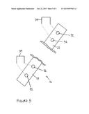
[0032] FIG. 1 of the drawings is an isometric view illustrating a pitching screen assembly in accordance with the present invention in a non-deployed position;
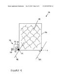
[0033] FIG. 2 of the drawings is an isometric view illustrating a pitching screen assembly in accordance with the present invention in a deployed position;
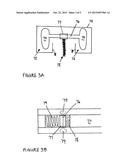
[0034] FIG. 3A of the drawings is a fragmented side-elevation view illustrating a channel associated with a frame sub-assembly of a pitching screen assembly in accordance with the present invention;
[0035] FIG. 3B of the drawings is a fragmented bottom elevation view illustrating a channel associated with a frame sub-assembly of a pitching screen assembly in accordance with the present invention;
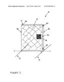
[0036] FIG. 4 of the drawings is a schematic illustration of a pitching screen assembly in accordance with the present invention having a remote control sub-assembly; and
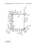
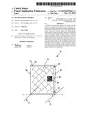
[0037] FIG. 5 of the drawings is a fragmented isometric view illustrating a ground-engaging support member and a securement stake in accordance with the present invention.
DETAILED DESCRIPTION OF THE INVENTION
[0038] While this invention is susceptible of embodiment in many different forms, there is shown in the drawings and will be described herein in detail, one or more specific embodiments with the understanding that the present disclosure is to be considered as an exemplification of the principles of the invention and is not intended to limit the invention to the embodiments illustrated.
[0039] It will be understood that like or analogous elements and/or components, referred to herein, are identified throughout the drawings by like reference characters. In addition, it will be understood that the drawings are merely schematic representations of one or more embodiments of the invention, and some of the components may have been distorted from their actual scale for purposes of pictorial clarity.
[0040] Referring now to the drawings, and to FIGS. 1 and 2 in particular, pitching screen assembly 10 is shown which is adapted to be readily converted between a non-deployed configuration (FIG. 1) and a deployed configuration (FIG. 2) preferably by actuating a releasable stop via direct and/or remote actuation. In the non-deployed configuration the internal aperture of the frame sub-assembly remains substantially open to allow a pitcher to pitch a ball with a normal throwing motion. However, in the deployed position the internal aperture of the frame sub-assembly is closed to protect a pitcher from, for example, a batted ball.
[0041] For purposes of the present disclosure, pitching screen assembly 10 generally comprises first ground-engaging support member 12, second ground-engaging support member 14, frame sub-assembly 16, and protective screen 18.
[0042] As is best shown in FIG. 1, first ground-engaging support member 12 preferably includes first end 20, second end 22, and midpoint 24, and second ground-engaging support member 14 preferably includes first end 26, second end 28, and midpoint 30.
[0043] As is best shown in FIG. 5, first ground-engaging support member 12 preferably includes apertures 32 for securing pitching screen assembly 10 to the ground via a stake, such as securement stake 34 (e.g., U-shaped, right-angled U-shaped (See FIG. 5)). It will be understood that second ground-engaging support member 14 also preferably includes apertures 32 for securement to the ground via securement stake 34.
[0044] In accordance with one embodiment of the present invention, first ground-engaging support member 12 and second ground-engaging support member 14 may each comprise a unitary support member, or, alternatively comprise a plurality of support members, such as two-piece, three-piece, four-piece, five-piece, etcetera. First and second ground-engaging support members 12 and 14, respectively, may be fabricated from natural and/or synthetic resins, plastics, woods, metals, composites, and/or combinations thereof. In a preferred embodiment of the present invention, first ground-engaging support member 12 and second ground-engaging support member 14 comprise tubular metal (e.g., tubular aluminum) and/or tubular plastic (e.g., tubular polyvinyl chloride (PVC)).
[0045] Referring once again to FIG. 1, and in a preferred embodiment of the present invention, frame sub-assembly 16 includes internal aperture 36 defined by bottom/base frame member 38, left frame member 40, top/upper frame member 42, and right frame member 44. In this embodiment: base frame member 38 includes left end 46, right end 48, and midpoint 50; left frame member 40 includes lower end 52, upper end 54, and midpoint 56; upper frame member 42 includes left end 58, right end 60, and midpoint 62; and right frame member 44 includes lower end 64, upper end 66, and midpoint 68.
[0046] In accordance with one embodiment of the present invention, frame sub-assembly 16 preferably comprises a unitary frame member, or, alternatively comprises a plurality of frame members, such as two-piece, three-piece, four-piece, five-piece, six-piece, etcetera. Frame sub-assembly 16 is preferably fabricated from natural and/or synthetic resins, plastics, woods, metals, composites, and/or combinations thereof. In a preferred embodiment of the present invention, and similarly to first ground-engaging support member 12 and second ground-engaging support member 14, frame sub-assembly 16 comprises tubular metal (e.g., tubular aluminum) and/or tubular plastic (e.g., tubular polyvinyl chloride (PVC)).
[0047] While frame sub-assembly 16 has been shown as comprising a rectangular outer peripheral geometry it will be understood that other peripheral geometries (e.g., triangular, square, pentagonal, polygonal, etcetera) and design configurations are likewise contemplated for use in accordance with the present invention.
[0048] Referring primarily to FIGS. 3A and 3B and secondarily to FIGS. 1, 2, and 4, guide rail 70 is associated with and/or integrated into bottom frame member 38 or top frame member 42, or both bottom and top frame members 38 and 42, respectively. It will be understood that guide rail 70 may alternatively and/or additionally be associated with left and/or right frame members 40 and 44, respectively. Indeed, in one embodiment of the present invention, protective screen 18 may be deployed downwardly in a manner analogous to a horizontal window blind. In this embodiment, protective screen 18 may, for example, include weights, rods, and/or magnets to assist in gravitational deployment, as well as retracted non-deployment. For example, opposite polarity magnets may be utilized to hold protective screen 18 in a non-deployed and/or deployed state--depending upon assembly configuration.
[0049] As is best shown in FIGS. 3A and 3B, guide rail 70 preferably includes a pair of channels 72 for retaining, for example, wheels 74 which are optionally connected via rod 76. In this embodiment protective screen 18 is preferably secured to rod 76 and/or alignment housing 77. Channels 72 preferably include lip members 78 which prevent wheels 74 or other displacement members from derailment. It will be understood that while guide rail 70 has been disclosed as comprising a pair of channels, a singular channel having one or more wheels is likewise contemplated for use in accordance with the present invention. In such an embodiment, the guide rail essentially comprises one-half of that disclosed in FIGS. 3A and 3B. It will be further understood that during normal operation, protective screen 18 is displaceable, preferably linearly, along the first axis (X) which emanates parallel to guide rail 70.
[0050] In one embodiment of the present invention, protective screen 18 is displaced via gravity, and in another embodiment protective screen 18 is displaced via one or more compression springs 79. It will be understood that protective screen 18 may also be displaced via, for example, a gas engine and/or an electric motor associated with a displacement and/or drive shaft--just to name a few.
[0051] Protective screen 18 may be displaceable from one or more sides 38, 40, 42, and 44 of frame sub-assembly 16, including dual or quad inwardly mating displacement of one or more protective screens 18. It will be further understood that protective screen 18 may be displaceable in a parallel, perpendicular, and/or any other angle (e.g., 1-90 degrees, 2 degrees, 5 degrees, 10 degrees, 25 degrees, 50 degrees, 65 degrees, 70 degrees, 75 degrees, 90 degrees, etcetera) relative to at least one of first ground-engaging support member 12, second ground-engaging support member 14, frame sub-assembly 16, and all sub-components thereof.
[0052] Referring once again to FIGS. 1 and 2, when in the non-deployed configuration (FIG. 1), deflection material and/or protective screen 18 only covers a minor portion of internal aperture 36 of frame sub-assembly 16. In this configuration internal aperture 36 of frame sub-assembly 16 is substantially open to allow a pitcher to pitch a ball through pitching screen assembly 10 with a normal throwing motion (i.e., without throwing over and/or around the pitching screen assembly). In comparison, when in the deployed configuration (FIG. 2), deflection material and/or protective screen 18 covers the entire or substantially the entire (+/-10%) internal aperture 36 of frame sub-assembly 16. In this deployed configuration, protective screen 18 is closed, thereby protecting a pitcher from a batted ball. It will be understood that protective screen 18 is preferably releasably lockable in the deployed configuration via, for example, a latch and/or one or more pairs of opposite polarity magnets 84. Such magnets are preferably associated with upper frame member 42 of frame sub-assembly 16 and protective screen 18.
[0053] Protective screen 18 may comprise a net having apertures sufficiently small to deflect batted balls. In a preferred embodiment, the net is fabricated from any one of a variety of materials, such as nylon, polyethylene, polypropylene, polyester, acrylic, metal strands, cotton fiber, Gore-Tex®, or the like, separately or in various combinations or permutations. The net made from these various materials, and others, can also be coated with a layer of a second material, such as vinyl, latex, and/or rubber. Preferably, the net comprises apertures from approximately 0.25 millimeter to approximately 50 millimeters--depending on the pitching application. The apertures preferably comprise any one of a number of various geometries, such as square, rectangular, hexagonal, diamond, polygonal, or the like. In an alternative embodiment, the deflection material or protective screen may comprise a mesh, a web, plastic sheeting, a woven sheeting, or the like.
[0054] In one aspect of the present invention, pitching screen assembly 10 includes linearly displaceable protective screen 18, and as shown in FIGS. 1 and 2 via arched arrows, rotationally (e.g., pivotally) displaceable frame sub-assembly 16 as is disclosed in U.S. patent application Ser. No. 14/256,271, filed Apr. 18, 2014, entitled "Pitching Screen Assembly," which is hereby incorporated herein by reference in its entirety, including all references cited therein.
[0055] As is best shown in FIG. 2, protective screen 18 may optionally include strike pad 80. Strike pad 80 facilitates rapid rotational displacement from an upright to a non-upright configuration--especially when protective screen 18 is fabricated from a flexible or semi-flexible and/or elastomeric netting material. Strike pad 80 preferably comprises a substantially transparent and/or colorless plastic substrate having sufficient rigidity so that the pitcher can strike a generally non-elastic region of protective screen 18.
[0056] As is further shown in FIGS. 1, 2, and 4, frame sub-assembly 16 and/or protective screen 18 preferably include one or more handle members 82.
[0057] In operation, a pitcher starts with the pitching screen assembly in the generally open, non-deployed configuration (FIG. 1). Next, the pitcher throws a ball to a batter through the pitching screen assembly with his/her normal throwing motion. After the ball has been pitched, either the pitcher directly via release of stop member 86 (e.g., a latch, a pivot pin, a solenoid, etcetera) or a third party via remote actuation disengages releasable stop member 86 to convert the pitching screen assembly to the deployed configuration which protects the pitcher from a batted ball.
[0058] In one embodiment of the present invention, pitching screen assembly 100 is shown which is adapted to be readily converted between a non-deployed configuration (not shown) and a deployed configuration (e.g., FIG. 4) via a remote control sub-assembly. The remote control sub-assembly enables, for example, a player, an umpire, a coach, a parent, and/or a volunteer to remotely actuate the pitching screen assembly between a deployed configuration and a non-deployed configuration, and, in certain embodiments, vice versa. Pitching screen assembly 100 is schematically shown in FIG. 4 as generally comprising: first ground-engaging support member 102 having a first end, a second end, and a midpoint, wherein the first end and the second end define a length therebetween; second ground-engaging support member 104 having a first end, a second end, and a midpoint, wherein the first end and the second end define a length therebetween; frame sub-assembly 106 having an internal aperture contained therein; protective screen 108, wherein the protective screen covers at least a portion of the internal aperture of the frame sub-assembly; and remote control sub-assembly 110 which preferably includes housing 112, actuating mechanism 114, energy source 116, receiver 118, and transmitter 120. It will be understood that the remote control sub-assembly may also include one or more inertia chargers and/or rectifiers, such as those disclosed in U.S. Pat. No. 7,952,477 entitled "Door Lock Assembly;" U.S. Pat. No. 6,794,783 entitled "Flat Rotary Electric Generator;" U.S. Pat. No. 6,717,297 entitled "Electrical Machine;" U.S. Pat. No. 5,631,507 entitled "Electric Power Generator;" U.S. Pat. No. 5,608,279, entitled "DC Generator;" U.S. Pat. No. 5,347,186 entitled "Linear Motion Electric Power Generator;" U.S. Pat. No. 5,089,734 entitled "Dual Rotary AC Generator;" U.S. Pat. No. 4,500,827 entitled "Linear Reciprocating Electrical Generator;" U.S. Pat. No. 4,385,246 entitled "Apparatus for Producing Electrical Energy," U.S. Pat. No. 4,217,508 entitled "DC Motor;" and U.S. Pat. No. 3,673,444 entitled "Rotary Electric Machine"-- all of which are hereby incorporated herein by reference in their entirety including all references cited therein.
[0059] Housing 112 preferably comprises, for example, a first wall and a second wall spaced apart from one another to define a cavity, or may also comprise first and second walls spaced apart from one another, as well as third and fourth walls spaced apart from one another such that the walls form a square, rectangular or other polygonal cavity for at least partially containing and/or retaining, for example, an actuating mechanism, an energy source, a receiver, and optionally one or more inertia chargers, and/or one or more optical sensors--among other components. For purposes of the present disclosure, housing 112 is preferably fabricated from natural and/or synthetic resins, plastics, metals, wood, etcetera. However, any one of a number of materials that would be known to those having ordinary skill in the art with the present disclosure before them are likewise contemplated for use. Housing 112 may also be advantageously manufactured from a waterproof material, thereby protecting the contents of the housing from the elements, or other outside contaminates.
[0060] Actuating mechanism 114 preferably comprises, for example, a displaceable bolt and/or plate driven by a motor, a displaceable bolt and/or plate driven by a solenoid, a sprocket, a gear, as well as other actuating means. Actuating mechanism 114 is preferably contained within the internal chamber of housing 110 and provides the means for facilitating displacement of the pitching screen assembly between a non-deployed configuration and a deployed configuration, and vice versa.
[0061] Energy source 116 preferably comprises, a power source, such as, for example, a primary and/or secondary electrochemical cell (e.g., NiCad, NIMH, Li-ion, etcetera), or any other self-contained energy source known to those with ordinary skill in the art. It is also contemplated that energy source 116 comprises a connection to an outside AC source (i.e., city power supply, generator, etcetera). However, for typical outdoor applications of pitching screen assembly 100, it is preferred that energy source 116 comprise a self-contained power source. Energy source 116 is preferably contained within the internal chamber of housing 110 and provides energy to actuating mechanism 114 and/or receiver 118.
[0062] Receiver 118 preferably comprises, a traditional receiver that operates on any one of a number of radio frequencies, including, but not limited to, those used for remote operation of a garage door. It will be understood that receiver 118 may optionally comprise a roaming code. Receiver 118 is preferably contained within the internal chamber of housing 110 and is in mechanical, electrical, and/or radio frequency communication with actuating mechanism 114, energy source 116, and transmitter 120.
[0063] Transmitter 120 preferably comprises a traditional transmitter that operates on any one of a number of radio frequencies, including, but not limited to, those used for remote operation of a garage door. Transmitter 120 comprises a hand held transmitter that is communication with receiver 118.
[0064] In this particular embodiment of the present invention, in operation a pitcher starts with the pitching screen assembly in the non-deployed configuration. Next, the pitcher throws a ball to a batter. After the ball is pitched, then a player, an umpire, a coach, a parent, and/or a volunteer activates the transmitter that sends a signal to the receiver which, in turn, activates the actuating mechanism to remotely actuate the pitching screen assembly from the non-deployed configuration to the deployed configuration. After the ball is returned to the pitcher, the pitching screen assembly can be rapidly returned to the non-deployed configuration via manual displacement and/or by remote displacement via the transmitter.
[0065] In another aspect of the present invention, an optional optical sensor associated with and/or positioned proximate to and/or in frame sub-assembly 106 or housing 112 may actuate the pitching screen assembly from the non-deployed configuration to the deployed configuration via actuating mechanism 114. In this embodiment deployment preferably occurs immediately after the ball has passed through frame sub-assembly 106.
[0066] The foregoing description merely explains and illustrates the invention and the invention is not limited thereto except insofar as the appended claims are so limited, as those skilled in the art who have the disclosure before them will be able to make modifications without departing from the scope of the invention.
User Contributions:
Comment about this patent or add new information about this topic:
Images included with this patent application:
 |  |
 |  |
 |  |
| Similar patent applications: | |
| Date | Title |
|---|---|
| 2015-11-05 | Interchangeable shaft and club head connection system |
| 2015-10-15 | Penetration type screen for screen golf |
| 2015-10-29 | Golf club with adjustable weight assembly |
| 2015-10-29 | Golf club with adjustable weight assembly |
| 2015-11-05 | Using pressure signal from racket to advise player |
| New patent applications in this class: | |
| Date | Title |
|---|---|
| 2016-06-02 | Pitching mat device |
| 2016-05-19 | Ball rotation indicator and method |
| 2016-05-05 | Sports training target |
| 2016-03-10 | Ball-hitting training device |
| 2016-03-10 | Apparatus, assembly kit, and methods for training overhead throwing motions and balance |
| Top Inventors for class "Games using tangible projectile" | |
| Rank | Inventor's name |
|---|---|
| 1 | Michael J. Sullivan |
| 2 | Brian Comeau |
| 3 | Derek A. Ladd |
| 4 | David A. Bulpett |
| 5 | Mark L. Binette |