Patent application title: HEAT PIPE STRUCTURE HAVING CIRCUITOUS CAPILLARY TISSUE
Inventors:
Hao Pai (Taoyuan County, TW)
Hao Pai (Taoyuan County, TW)
IPC8 Class: AF28D1504FI
USPC Class:
Class name:
Publication date: 2015-07-16
Patent application number: 20150198377
Abstract:
A heat pipe having a circuitous capillary tissue includes a pipe body and
a capillary tissue installed in the pipe body. The interior of the pipe
body is formed with a vapor flow channel which is hollow and extended
towards the length direction thereof, and a working fluid is stored
therein; the capillary tissue is formed with a primary capillary part,
two secondary capillary parts, and communicating capillary parts
connected between the primary and the secondary capillary parts; wherein,
the two secondary capillary parts are both extended along the length
direction of the pipe body and respectively abutted against two lateral
walls extended along the length direction of a pipe member, and two sides
of the primary capillary part are both formed with a space allowing the
vapor flow channel to be kept.Claims:
1. A heat pipe structure having a circuitous capillary tissue, including:
a pipe body, formed with a pipe member and two end parts respectively
sealing two ends of the pipe member, wherein the interior of the pipe
member is formed with a vapor flow channel which is hollow and extended
along a length direction thereof, and a working fluid is stored therein;
and a capillary tissue, installed in the pipe body, and formed with a
primary capillary part, two secondary capillary parts and two
communicating capillary parts which are all formed in a strip-like shape
and pass the vapor flow channel, wherein the communicating capillary
parts are connected between the primary and the secondary capillary parts
thereby continuously forming a circuitous status; wherein, the two
secondary capillary parts are both extended along the length direction of
the pipe body and respectively abutted against two lateral walls extended
along the length direction of the pipe member, and two sides of the
primary capillary part are both formed with a space allowing the vapor
flow channel to be kept.
2. The heat pipe structure having the circuitous capillary tissue according to claim 1, wherein a cross section of the pipe body is formed in a flat status.
3. The heat pipe structure having the circuitous capillary tissue according to claim 1, wherein the thickness of the pipe body is smaller than 0.6 mm.
4. The heat pipe structure having the circuitous capillary tissue according to claim 1, wherein the capillary tissue is formed as a strip-like member through sintering powders, weaving fibers or metal wires or reeling a metal net.
5. The heat pipe structure having the circuitous capillary tissue according to claim 1, wherein the two communicating capillary parts of the capillary tissue are respectively abutted against an inner partial portion respectively defined at the two end parts.
6. The heat pipe structure having the circuitous capillary tissue according to claim 1, wherein the two communicating capillary parts of the capillary tissue are respectively formed in an arc-like status or a linear status.
7. The heat pipe structure having the circuitous capillary tissue according to claim 1, wherein each of the two secondary capillary parts of the capillary tissue is formed with an auxiliary capillary part extended from a free end thereof.
8. The heat pipe structure having the circuitous capillary tissue according to claim 7, wherein the auxiliary capillary part is further extended with an abutting segment towards the primary capillary part thereby being abutted against the primary capillary part, so the capillary tissue is further formed in a loop-like status.
9. The heat pipe structure having the circuitous capillary tissue according to claim 7, wherein the auxiliary capillary part is formed in an arc-like status or a linear status.
Description:
FIELD OF THE INVENTION
[0001] The present invention relates to a capillary tissue, especially to a heat pipe structure having a circuitous capillary tissue.
DESCRIPTION OF RELATED ART
[0002] A conventional capillary tissue installed in a heat pipe is mostly formed through weaving fibers or metal wires or reeling a metal net, and after the weaving or reeling process is finished, a bending status oriented towards no specified direction is formed because of the elastic recovering force provided by the material itself; when the above-mentioned capillary tissue is disposed in a pipe body of a heat pipe, a problem of difficult in disposing may be caused, or other problems such as not being able to be precisely positioned and formed in a desired status may also be caused.
[0003] Take a strip-like capillary tissue (such as a capillary tissue having coaxially-arranged fibers) for example, the strip-like shape makes the capillary tissue hard to be kept in a linear status when being disposed in a heat pipe, and a forming space is required to be reserved for allowing a vapor flow channel to be formed, so the capillary tissue is often installed at single side in the pipe body of the heat pipe thereby reducing the vaporization area and lowering the heat transferring effect. If two sides are respectively installed with a strip-like capillary tissue, the two capillary tissues are spaced far away from each other thereby being unable perform mutual transfer, and a returning effect for a liquid-state working fluid is affected, also a problem of recessing may be happened during a gas discharging operation.
[0004] Accordingly, the applicant of the present invention has devoted himself for researching and inventing a novel structure for improving the above-mentioned shortages.
SUMMARY OF THE INVENTION
[0005] The present invention is to provide a heat pipe having a circuitous capillary tissue, in which a linear capillary tissue is circuitously arranged for being disposed in a heat pipe, so the capillary tissue is easier to be positioned or formed in a desired status, thereby enabling the capillary tissue to be effectively positioned in the heat pipe and to be served as a supporting structure for preventing the pipe body from recessing.
[0006] Accordingly, the present invention provides a heat pipe having a circuitous capillary tissue, which includes a pipe body and a capillary tissue installed in the pipe body; the pipe body is formed with a pipe member and two end parts respectively sealing two ends of the pipe member, and the interior of the pipe member is formed with a vapor flow channel which is hollow and extended towards the length direction thereof, and a working fluid is stored therein; the capillary tissue is formed with a primary capillary part, two secondary capillary parts and communicating capillary parts which are all formed in a strip-like shape and pass the vapor flow channel, the communicating capillary parts are connected between the primary and the secondary capillary parts thereby continuously forming a circuitous status; wherein, the two secondary capillary parts are both extended along the length direction of the pipe body and respectively abutted against two lateral walls extended along the length direction of the pipe member, and two sides of the primary capillary part are both formed with a space allowing the vapor flow channel to be kept.
BRIEF DESCRIPTION OF DRAWING
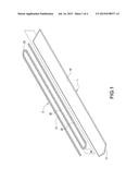
[0007] FIG. 1 is a perspective exploded view according to a first embodiment of the present invention;
[0008] FIG. 2 is a perspective view showing the assembly according to the first embodiment of the present invention;
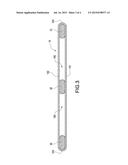
[0009] FIG. 3 is a cross sectional view according to the first embodiment of the present invention;
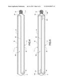
[0010] FIG. 4 is a plane cross sectional view showing the internal structure according to the first embodiment of the present invention; and
[0011] FIG. 5 is a plane cross sectional view showing the internal structure according to a second embodiment of the present invention.
DETAILED DESCRIPTION OF THE INVENTION
[0012] Preferred embodiments of the present invention will be described with reference to the drawings.
[0013] Please refer from FIG. 1 to FIG. 3, wherein FIG. 1 is a perspective exploded view according to a first embodiment of the present invention; FIG. 2 is a perspective view showing the assembly according to the first embodiment of the present invention; and FIG. 3 is a cross sectional view according to the first embodiment of the present invention. The present invention provides a heat pipe structure having a circuitous capillary tissue includes a pipe body 1 and a capillary tissue 2 installed in the pipe body 1.
[0014] The pipe body 1 is formed as an elongated hollow tubular body, a cross section thereof is formed in a flat status, and a working fluid (not shown in figures) is stored therein. According to this embodiment provided by the present invention, a flattening treatment is processed for achieving the above-mentioned flat status thereby being able to be disposed in an ultra-thin heat pipe (having a thickness smaller than 0.6 mm). As shown in FIG. 1, before the pipe body 1 is sealed, the pipe body 1 is formed with a pipe member 10 and an end part 11 sealing one end of the pipe member 10, and the interior of the pipe member 10 is formed with a vapor flow channel 100 (as shown in FIG. 3) which is hollow and extended along the length direction of the pipe body 1 and communicated with the other end of the pipe member 10 which is formed in an opened status, thereby allowing the capillary tissue 2 to be disposed in the vapor flow channel 100; when the capillary tissue 2 is disposed in the pipe body 1 and the air inside the pipe body 1 is discharged, the other end of the pipe member 10 is sealed thereby forming another end part 11', and a sealing structure 12 is formed at the end part 11'.
[0015] The capillary tissue 2 is formed as a strip-like member through sintering powders, weaving fibers or metal wires or reeling a metal net, and the capillary tissue 2 is installed in the above-mentioned pipe body 1. As shown in FIG. 3 and FIG. 4, the pipe member 10 of the pipe body 1 is further formed with a bottom wall 101, a top wall 102, and two lateral walls 103 surrounding the bottom wall 101 and the top wall 102, and the above-mentioned vapor flow channel 100 is defined by the bottom wall 101, the top wall 102 and the two lateral walls 103. The capillary tissue 2 is formed with a primary capillary part 20, two secondary capillary parts 21, 22 and two communicating capillary parts 23, 24 which are all formed in a strip-like shape and pass the vapor flow channel 100, the communicating capillary parts 23, 24 are connected between the primary and the secondary capillary parts 20, 21, 22 thereby continuously forming a circuitous status, and the two secondary capillary parts 21, 22 are both extended along the length direction of the pipe body 1 and respectively abutted against the two lateral walls 103, the primary capillary part 20 is arranged between the two secondary capillary parts 21, 22, and two sides of the primary capillary part 20 are both formed with a space allowing the vapor flow channel 100 to be kept; in addition, the two communicating capillary parts 23, 24 are respectively formed in an arc-like status or a linear status and respectively abutted against an inner partial portion defined at one of the end parts 11, 11' of the pipe body 1, thereby being able to be connected between the primary and the secondary capillary parts 20, 21, 22, and the liquid-state working fluid is allowed to be transferred between the primary and the secondary capillary parts 20, 21, 22.
[0016] Accordingly, with the above-mentioned structure, the heat pipe structure having the circuitous capillary tissue is assembled.
[0017] Please refer to FIG. 4, the capillary tissue 2 is disposed in the pipe body 1 with a circuitously-arranged manner, and the two secondary capillary parts 21, 22 are abutted against the two lateral walls 103 thereby being formed in a bending status so as be easier to be positioned inside the pipe body 1, because of the connecting effect provided by the communicating capillary part 22, the primary and the secondary capillary parts 20, 21, 22 enable to the liquid-state working fluid to be transferred therebetween, meanwhile the vapor flow channel 100 can be kept at the spaces formed at two sides of the primary capillary part 20, thereby clogging being prevented and the gaseous working fluid being able to perform heat transferring.
[0018] As shown in FIG. 5, which discloses a second embodiment provided by the present invention; the secondary capillary parts 21, 22 can be respectively formed with an arc-like or linear auxiliary capillary part 210, 220 extended from a free end thereof, and the two auxiliary capillary parts 210, 220 are further extended with an abutting segment 211, 221 towards the primary capillary part 20 thereby being abutted against the primary capillary part 20. As such, the capillary tissue 2 in the circuitous status can be further formed in a loop-like status for allowing the liquid-state working fluid to be transferred in a relatively smoother fashion in the capillary tissue 2.
[0019] According to the heat pipe structure having the circuitous capillary tissue provided by the present invention, the capillary tissue 2 is formed in the circuitous status for being installed in the pipe body 1, and the two secondary capillary parts 21, 22 are abutted against the two lateral walls 103 for being arranged in a bending status thereby being easier to be positioned inside the pipe body 1, and the connecting effect provided by the communicating capillary parts 23, 24 allows the liquid-state working fluid to be transferred between the primary and the secondary capillary parts 20, 21, 22, meanwhile the vapor flow channel 100 is able to be kept in the spaces formed at two sides of the primary capillary part 20 thereby clogging being prevented and the gaseous working fluid being able to perform heat transferring. Moreover, instead of being abutted against the two lateral walls 103 of the pipe body 1, the primary capillary part 20 is abutted between the bottom wall 101 and the top wall 102 of the pipe body 1, thereby being able to be served as a supporting structure in the pipe body 1 and preventing a problem such as recessing from happening during the gas discharging operation.
[0020] Although the present invention has been described with reference to the foregoing preferred embodiment, it will be understood that the invention is not limited to the details thereof. Various equivalent variations and modifications can still occur to those skilled in this art in view of the teachings of the present invention. Thus, all such variations and equivalent modifications are also embraced within the scope of the invention as defined in the appended claims.
User Contributions:
Comment about this patent or add new information about this topic:
| People who visited this patent also read: | |
| Patent application number | Title |
|---|---|
| 20150279710 | Substrate carrier having drip edge configurations |
| 20150279709 | REDUCING WAFER BONDING MISALIGNMENT BY VARYING THERMAL TREATMENT PRIOR TO BONDING |
| 20150279708 | SUBSTRATE TREATMENT METHOD AND SUBSTRATE TREATMENT APPARATUS |
| 20150279707 | SUBSTRATE SEPARATION DEVICE AND SUBSTRATE SEPARATION SYSTEM |
| 20150279706 | COMPOSITE SEAL |
Images included with this patent application:
 |  |
 |  |
 |
| New patent applications in this class: | |
| Date | Title |
|---|---|
| 2022-09-08 | Shrub rose plant named 'vlr003' |
| 2022-08-25 | Cherry tree named 'v84031' |
| 2022-08-25 | Miniature rose plant named 'poulty026' |
| 2022-08-25 | Information processing system and information processing method |
| 2022-08-25 | Data reassembly method and apparatus |
| New patent applications from these inventors: | |
| Date | Title |
|---|---|
| 2015-07-16 | Heat pipe structure having strip-shaped capillary tissue at both side ends thereof |
| 2015-07-16 | Heat pipe structure having capillary tissue formed with end part for supporting |
| 2015-07-16 | Heat pipe structure with deformable wick structure |
| 2015-06-25 | Coaxial capillary structure and ultra-thin heat pipe structure having the same |
| 2015-06-25 | Flat mesh wick structure of ultrathin heat pipe and ultrathin heat pipe having the same |