Patent application title: VIBRATORY HAMMER HAVING SEQUENTIALLY CONTROLLABLE SLIDING GRIPPER
Inventors:
Seng Hyun Park (Gwangmyeong-Si, KR)
Jeong Woo Lee (Seoul, KR)
Assignees:
FEEL INDUSTRIAL ENGINEERING CO., LTD.
IPC8 Class: AE02D718FI
USPC Class:
Class name:
Publication date: 2015-07-16
Patent application number: 20150197910
Abstract:
Disclosed is a vibratory hammer used to drive a pile in a foundation work
of a construction site. A pair of main grip portions of a main gripper
capable of gripping a pile are mounted on a pair of sliding arms capable
of linear reciprocation. While the main grip portions and the sliding
arms make linear reciprocation, a gap between the main grip portions is
adjusted depending on a size and a shape of the pile (primary sliding
operation). While a jaw pad of the main grip portion that substantially
grips the pile also makes linear reciprocation by virtue of self-power of
the main grip portion, the pile is gripped (secondary sliding operation).
The primary and secondary sliding operations are sequentially performed.Claims:
1. A sequentially controllable sliding gripper type vibratory hammer
comprising: a main housing having a vibrator for striking a pile; a pair
of sliding arms provided to face each other and linearly reciprocatable
inside the main housing; an arm-actuating cylinder provided inside the
main housing to move the pair of sliding arms; and a pair of left and
right main grip portions mounted on the pair of sliding arms,
respectively, the main grip portions moving along with the sliding arms
to grip a pile by interposing a linearly and independently reciprocatable
jaw pad.
2. The sequentially controllable sliding gripper type vibratory hammer according to claim 1, wherein each of the main grip portions includes a cylinder body, a rod that linearly slides in or out of the cylinder body, and a jaw pad that is provided in an end of the rod in a circular plate shape and has a plurality of wedged protrusions on a grip surface for gripping the pile.
3. The sequentially controllable sliding gripper type vibratory hammer according to claim 2, wherein a pair of arm-actuating cylinders are provided for the pair of sliding arms, and each of the arm-actuating cylinders pushes or pulls each of the sliding arms in parallel.
4. The sequentially controllable sliding gripper type vibratory hammer according to claim 3, wherein an upper plate and a lower plate are provided over and under the main grip portion, respectively, across an interior of the main housing, and the pair of arm-actuating cylinders are arranged oppositely in the left and right sides of the upper and lower plates.
5. The sequentially controllable sliding gripper type vibratory hammer according to claim 4, further comprising a pair of left and right slide pins slidably connected to the pair of sliding arms to guide left-right linear reciprocation of the sliding arms, the pair of slide pins being provided in each of the upper and lower plates.
6. The sequentially controllable sliding gripper type vibratory hammer according to claim 5, wherein each of the sliding arms includes a front plate coupled to the main grip portion, a side plate arranged perpendicularly to the front plate, and a connecting bracket extending from the side plate in an integral manner and having upper and lower slide pinholes where the slide pins are inserted.
7. The sequentially controllable sliding gripper type vibratory hammer according to claim 6, wherein a rod passage hole where a rod of the main grip portion is inserted is formed in a center of the front plate of each of the pair of sliding arms.
8. The sequentially controllable sliding gripper type vibratory hammer according to claim 6, wherein a first rod pin hole where a rod pin is inserted is formed in an end of a rod of the arm-actuating cylinder, and the connecting bracket of the sliding arm has a second rod pin hole where the rod pin inserted into the first rod pin hole is inserted.
9. The sequentially controllable sliding gripper type vibratory hammer according to claim 1, further comprising a subsidiary gripper configured to vertically drive a pile in a finish pile socketing, wherein the subsidiary gripper includes a fixed grip portion and a movable grip portion arranged to face each other in a lower portion of the main housing to grip an upper end of the pile.
Description:
CROSS REFERENCES TO RELATED APPLICATIONS
[0001] The present invention contains subject matter related to Korean Patent Application No. 10-2014-0005173, filed in the Korean Patent Off ice on Jan. 15, 2014, the entire contents of which are incorporated herein by reference.
BACKGROUND OF THE INVENTION
[0002] 1. Field of the Invention
[0003] This disclosure relates to a vibratory hammer, and more particularly, to a vibratory hammer used to drive e a pile in a foundation work of a construction site.
[0004] 2. Description of Related Art
[0005] In general, in order to build many types of structures such as concrete buildings or bridges on the ground, it is necessary to perform a foundation work for burying a concrete pile, a steel pipe pile, an H-beam, or the like in order to allow the ground to support the weight of the structure.
[0006] Such a piling work is very important in construction of structures or buildings. In particular, if the ground is soft, it is necessary to perform a foundation work for drilling and fixing a pile in a rock under the ground surface.
[0007] In such a foundation work, a work of drilling a pile into the ground is referred to as a pile driving work.
[0008] In a recent pile driving work, a vibratory hammer is employed. In this method, a vibrator is operated to vibrate a chuck in a driving direction, that is, in a direction perpendicular to the pile while a pile is fixed. This vibration of the pile reduces a frictional force between the pile and the ground to facilitate a driving work.
[0009] Such a vibratory hammer is installed in a boom of a construction machine such as an excavator and a shovel used in a civil engineering construction, a building construction, and the like to perform a pile socketing work.
[0010] In Korean Patent No. 10-0962081, US 2008-0310923A1, and the like, there is disclosed a vibratory hammer, in which a main body includes an internal vibrator for striking a pile and a pair of left and right grippers for gripping a pile and then socketing the pile into a pile hole.
[0011] In such vibratory hammers of the related art, a pile is gripped by actuating cylinders provided in both sides of each gripper while a pair of left and right grippers are fixed inside the main body. However, in this case, since the width of the gripper widened by both cylinders is limited, it is difficult to grip a large-sized pile or beam.
[0012] In addition, in the vibratory hammers of the related art, a pair of left and right grippers have a circular arc shape, and a pile is gripped by widening or narrowing a gap between the grippers while one end is rotated with respect to a shaft as the cylinder is actuated. However, in this case, since a direction where the cylinder pushes is different from a direction where the gripper grips the pile, the gripper fails to receive a force in a direction where the cylinder rod is actuated, and a force exerting direction changes depending on a pivot angle. Therefore, an eccentric force is applied, so that the gripper may be easily distorted. This may generate a deformation or failure of the gripper and reduce a gripping force of the gripper.
SUMMARY OF THE INVENTION
[0013] In view of the aforementioned problems, a need exists for a vibratory hammer capable of flexibly coping with various types of pile driving works for piles having various types and sizes, such as a sheet pile, a steel pipe pile, an H-beam, or an I-beam.
[0014] In addition, a need also exists for a vibratory hammer capable of increasing a gripping force of the gripper while reducing a deformation or failure of the gripper.
[0015] According to an aspect of this disclosure, there is provided a sequentially controllable sliding gripper type vibratory hammer comprising: a main housing having a vibrator for striking a pile; a pair of sliding arms provided to face each other and linearly reciprocatable inside the main housing; an arm-actuating cylinder provided inside the main housing to move the pair of sliding arms; and a pair of left and right main grip portions mounted on the pair of sliding arms, respectively, the main grip portions moving along with the sliding arms to grip a pile by interposing a linearly and independently reciprocatable jaw pad.
[0016] In the vibratory hammer described above, each of the main grip portions may include a cylinder body, a rod that linearly moves to or out of the cylinder body, and a jaw pad that is provided in an end of the rod in a circular plate shape and has a plurality of wedged protrusions on a grip surface for gripping the pile.
[0017] In the vibratory hammer described above, a pair of arm-actuating cylinders may be provided for the pair of sliding arms, and each of the arm-actuating cylinders may push or pull each of the sliding arms in parallel.
[0018] The vibratory hammer described above may further comprise a pair of left and right slide pins slidably connected to the pair of sliding arms to guide left-right linear reciprocation of the sliding arms, the pair of slide pins being provided in each of the upper and lower plates.
[0019] In the vibratory hammer described above, each of the sliding arms may include a front plate that is coupled to the main grip portion and has a rod passage hole where a rod of the main grip portion is inserted in its center, a side plate arranged perpendicularly to the front plate, and a connecting bracket extending from the side plate in an integral manner and having upper and lower slide pin holes where the slide pins are inserted.
[0020] Meanwhile, the vibratory hammer described above may further comprise a subsidiary gripper configured to vertically drive a pile during a finish pile socketing, wherein the subsidiary gripper includes a fixed grip portion and a movable grip portion arranged to face each other in a lower portion of the main housing to grip an upper end of the pile
[0021] The sequentially controllable sliding gripper type vibratory hammer according to an embodiment of this disclosure has the following effects.
[0022] First, since a sequential sliding gripper is employed, in which a pair of left and right main grip portions linearly reciprocates in the front-back direction unlike a fixed type, and the jaw pad of each main grip portion also reciprocates in the front-back direction, it is possible to further widen a gap between the main grip portions for gripping a pile without increasing a size of the vibratory hammer. Accordingly, it is possible to grip a pile having a larger size and perform a pile driving work for various types and sizes.
[0023] Second, a pair of left and right main grip portions are implemented in a sliding type unlike a pivot type. In addition, a movement direction (pile gripping direction) of the sliding arm connected to the main grip portion is in parallel with an actuating direction of the arm-actuating cylinder for driving the main grip portion. Therefore, there is no possibility of distortion in the main grip portion or the sliding arm. Therefore, it is possible to prevent a deformation or failure of the gripper and improve a gripping force of the gripper.
BRIEF DESCRIPTION OF THE DRAWINGS
[0024] The foregoing and additional features and characteristics of this disclosure will become more apparent from the following detailed description considered with reference to the accompanying drawings, wherein:
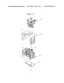
[0025] FIG. 1 is an exploded perspective view illustrating a vibratory hammer according to an embodiment of this disclosure;
[0026] FIG. 2 is a perspective view illustrating a vibratory hammer according to an embodiment of this disclosure;
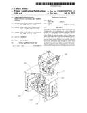
[0027] FIG. 3 is a front view illustrating a vibratory hammer according to an embodiment of this disclosure;
[0028] FIG. 4 is a top plan view illustrating a vibratory hammer according to an embodiment of this disclosure;
[0029] FIG. 5 is a side view illustrating a vibratory hammer according to an embodiment of this disclosure;
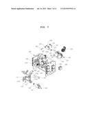
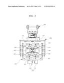
[0030] FIG. 6 is a perspective view illustrating a main housing of the vibratory hammer according to an embodiment of this disclosure;
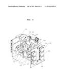
[0031] FIG. 7 is an exploded perspective view illustrating a main housing of the vibratory hammer according to an embodiment of this disclosure;
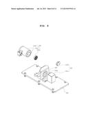
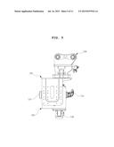
[0032] FIG. 8 is an exploded perspective view illustrating a subsidiary gripper of the vibratory hammer according to an embodiment of this disclosure; and
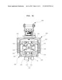
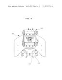
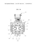
[0033] FIGS. 9A to 9C are operational state diagrams illustrating an operational state of the vibratory hammer according to an embodiment of this disclosure.
DETAILED DESCRIPTION OF THE INVENTION
[0034] Hereinafter, Hereinafter, an embodiment of this disclosure will be described in detail with reference to the accompanying drawings.
[0035] FIG. 1 is an exploded perspective view illustrating a vibratory hammer according to an embodiment of this disclosure. FIGS. 2 to 5 are a perspective view, a front view, a top plan view, and aside view, respectively, illustrating the vibratory hammer according to an embodiment of this disclosure.
[0036] Referring to FIGS. 1 to 5, the vibratory hammer includes a mount cap 300, a housing bracket 200, a main housing 100, and a mount plate 104.
[0037] The mount cap 300 is connected to a boom bracket, a quick coupler, or the like provided in a leading end of a boom of a construction machine such as an excavator and a shovel.
[0038] The housing bracket 200 is interposed between the mount cap 300 and the main housing 100 to couple the main housing 100 to the mount cap 300 and serves as a cover for protecting an exterior of the main housing 100. It is noted that a concave portion 201 hollowed inward from the front surface is formed in the upper plate of the housing bracket 200 to prevent an interference to a pile when the main gripper installed in the main housing 100 grips the pile.
[0039] The main housing 100 provides a space for housing the main gripper having a pair of main grip portions 130 used to grip a pile, an actuating cylinder 120 as an actuator for actuating the main gripper, and a vibrator 150 that provides vibration for socketing a pile into a piling hole of the ground.
[0040] The mount plate 104 is configured to finish the bottom of the main housing 100 in a rectangular plate shape and is provided with a subsidiary gripper 140 capable of gripping an upper end of the pile.
[0041] In the vibratory hammer according to an embodiment of this disclosure configured as described above, the main gripper grips the pile in a sequential sliding manner. Specifically, a pair of the main grip portions 130 are not fixedly installed in the main housing, but are installed in a linearly reciprocatable manner along a front-back direction (primary sliding). In addition, each of the main grip portions 130 also includes an actuator such as a motor or a cylinder, capable of driving a jaw pad that directly grips the pile by virtue of self-power (secondary sliding).
[0042] In this regard, FIGS. 6 and 7 are a perspective view and an exploded perspective view, respectively, illustrating the main housing of the vibratory hammer embedded with the main gripper described above.
[0043] Referring to FIGS. 2 to 7, the main housing 100 is internally provided with a pair of left and right assemblies arranged symmetrically. Each assembly includes a main grip portion 130 configured to grip a pile, a sliding arm 110 that is connected to the main grip portion 130 and reciprocates in the front-back direction, an arm-actuating cylinder 120 that provides a driving force for actuating the sliding arm 110, and a vibrator 150 that applies vibration for striking the pile.
[0044] The main housing 100 has a rectangular frame shape having an opened front surface. More specifically, the main housing 100 includes a pair of side plates 101 vertically erected in both sides to face each other, a rear plate (not illustrated) vertically erected in the back side and connected between the pair of side plates 101, and upper and lower plates 102 and 103 extending horizontally across the interior of the main housing 100 to face each other below an upper end of the pair of side plates 101 and above a lower end of the pair of side plates 101, respectively.
[0045] A pair of sliding arms 110 serving as a member for moving the main grip portion 130 are symmetrically provided to face each other in a space formed between the upper and lower plates 102 and 103 of the main housing 100. The pair of sliding arms 110 linearly reciprocates in the left-right direction by actuating the arm-actuating cylinder 120.
[0046] Now, the sliding arm 110 will be described more specifically with reference to FIG. 7. The sliding arm 110 generally includes a front plate 111, a side plate 112, and a connecting bracket 113.
[0047] A rod passage hole 111a where a rod 132 of the main grip portion 130 is inserted is formed in the center of the front plate 111. A plurality of fastening holes are formed around the rod passage hole 111a. Bolts are inserted into the fastening holes and are fastened to connect the cylinder body 131 of the main grip portion 130 to the front plate 111. In an integral manner, the side plate 112 extends perpendicularly to the front plate 11 in the end of the front plate 111, and the connecting bracket 113 vertically extends on a surface opposite to a surface where the main grip portion 130 is provided.
[0048] Meanwhile, a member for guiding the linear front-back reciprocation of the sliding arm 110 is provided in the main housing 100.
[0049] For this purpose, a pair of the slide pins 105 extending horizontally side by side are provided in the upper and lower plates 102 and 103 of the main housing 100 for each of the left and right assemblies (a total of four slide pins 105 are provided). One end of each slide pin 105 is fixed to the side plate 101 of the main housing 100 in a penetrating manner, and the other end is fixed to a slide pin bracket 108 protrudingly provided in the upper or lower plate 102 or 103 in a penetrating manner.
[0050] Each sliding arm 110 linearly reciprocates in the front-back direction along the slide pin 105 while it is slidably engaged with a pair of upper and lower slide pins 105 provided over and under the sliding arm 110, respectively.
[0051] For this purpose, a slide pin hole 113a where the slide pin 105 is inserted is formed in each of the upper and lower portions of the connecting bracket 113 of the sliding arm 110.
[0052] A single arm-actuating cylinder 120 serving as a member for linearly reciprocating the sliding arm 110 in the front-back direction is provided for each of the pair of sliding arms 110. A pair of sliding arms 110 are arranged oppositely in the left and right sides of the upper and lower plates 102 and 103 of the main housing 100.
[0053] For example, one of the arm-actuating cylinders 120 is arranged in the right side of the upper plate 102 to actuate the right sliding arm 110 of the main housing 100, and the other arm-actuating cylinder 120 is arranged in the left side of the lower plate 103 to actuate the left sliding arm 110 of the main housing 100.
[0054] A pair of arm-actuating cylinders 120 are arranged to face each other in the opposite direction. Specifically, the arm-actuating cylinders 120 are arranged such that the rear surfaces of the cylinder bodies turn back to each other while each cylinder rod is directed to the side plate 101 of the main housing 100.
[0055] The rod of the arm-actuating cylinder 120 is connected to the sliding arm 110 while the arm-actuating cylinder 120 is provided in parallel with the upper and lower plates 102 and 103. As a result, the sliding arm 110 can linearly reciprocate in the front-back direction in parallel with the actuating direction of the rod of the arm-actuating cylinder 120.
[0056] A rear end of the cylinder body of the arm-actuating cylinder 120 is fixed to a cylinder bracket 108 protrudingly provided at a certain height from the upper or lower plate 102 or 103 using a pin. A front end of the rod of the arm-actuating cylinder 120 is also connected to the sliding arm 110 using a pin.
[0057] A structure for fixing the arm-actuating cylinder 120 to the upper or lower plate 102 or 103 will be described in more detail. A cylinder pin hole 122 where the cylinder pin 106 is inserted is perforated in the rear end of the cylinder body of the arm-actuating cylinder 120 in the front-back direction. In addition, the cylinder bracket 108 has a pair of plates facing each other with a certain interval, and each plate has a cylinder pin hole 108a perforated in the front-back direction, where the cylinder pin 106 is inserted. As a result, the arm-actuating cylinders 120 are fixed to the upper and lower plates 102 and 103 of the main housing 100 by horizontally inserting the cylinder pin 106 into each of the cylinder pin holes 122 and 108a while a part of the arm-actuating cylinder 120 where the cylinder pin hole 122 is formed is interposed between the cylinder bracket 108.
[0058] A structure of coupling the arm-actuating cylinder 120 and the sliding arm 110 will be described in more detail. A rod pin hole 121 where the rod pin 107 is inserted is perforated in a front end of the rod of the arm-actuating cylinder 120 along a vertical direction. In addition, a rod pin hole 113b perforated along a vertical direction in an extending portion horizontally extending from a portion where the slide pin hole 113a is formed in the upper or lower portion of the connecting bracket 113 of the sliding arm 110. As a result, while the rod pin hole 121 of the arm-actuating cylinder 120 and the rod pin hole 113b of the connecting bracket 113 of the sliding arm 110 are disposed concentrically along a vertical direction, the rod pin 107 is vertically inserted into each rod pin hole 121 and 113b, so that the arm-actuating cylinder 120 and the sliding arm 100 are connected to each other.
[0059] A pair of main grip portions 130 of the main gripper are configured to grip a pile and guide the pile in an initial pile socketing. Each main grip portion 130 is mounted on the sliding arm and linearly reciprocates in the left-right direction along with the sliding arm.
[0060] As a result, a pair of left and right main grip portions 130 move a pile such as a sheet pile, a steel pipe pile, an H-beam, or an I-beam having different sizes to be close to or apart from each other inside the main housing in order to adjust a gap therebetween.
[0061] Meanwhile, the main grip portion 130 includes an actuator member such as a motor or a cylinder. Therefore, as recognized from FIGS. 9A to 9C, the pile can be gripped by advancing the jaw pad 133 disposed in the front surface by actuating the actuator.
[0062] According to an embodiment of this disclosure, a cylinder is employed as an actuator member.
[0063] This will be described in more detail with reference to FIG. 6. The main grip portion 130 includes a cylinder body 131 where a hydraulic pressure is internally applied, a rod 132 that slides into or out of the cylinder body 131 to make a linear reciprocation, and a jaw pad 133 coupled to an end of the rod 132. A pair of main grip portions 130 are horizontally mounted on the sliding arm 110 such that the jaw pads 133 face each other.
[0064] The jaw pad 133 having a circular plate shape is coupled to a leading edge of the rod 132 by fastening a bolt or the like, and a surface for gripping a pile has a plurality of wedged protrusions. As a result, it is possible to stably grip a pile without a problem such as slipping when the pile is gripped.
[0065] As described above, the main grip portion 130 is fixedly coupled to the front plate 111 of the sliding arm 110. Specifically, while the rod of the main grip portion 133 is inserted into the rod passage hole 111a formed in the center of the front plate 111 of the sliding arm 110, a front surface of the cylinder body 131 is fixedly coupled to the front plate 111 of the sliding arm 110 by fastening bolts through a plurality of fastening holes formed along the periphery of the rod passage hole 111a.
[0066] As a result, a gap for gripping the pile is adjusted as the main grip portions 130 make a linear movement along with the sliding arms 110 such that the gap can be widened or narrowed (primary sliding). In addition, as the rod 132 attached to the jaw pad 133 makes a linear reciprocation depending on the hydraulic pressure of the cylinder body 131, the pile is gripped or released (secondary sliding).
[0067] Meanwhile, the vibrator 150 is provided in a rear plate of the main housing 100. Therefore, vibration is generated using a pair of eccentric weights 153 and a pair of driving gears 152 operated by the motor 151.
[0068] For this purpose, a rotational shaft 154 is provided to extend across the eccentric weight 153, and a motor 151 for driving the rotational shaft 154 is provided in one of the pair of eccentric weights 153. In addition, a pair of driving gears 152 meshing with each other are coupled to the corresponding rotational shafts 154.
[0069] Therefore, as the motor 151 is operated, both the driving gears 152 meshing with each other are driven by virtue of rotation of the rotational shaft 154. Finally, vibration is generated by virtue of an eccentric rotational force exerted by a pair of eccentric weights 153. This vibration is used to strike the pile.
[0070] In addition, a subsidiary gripper 140 capable of vertically driving the pile during the finish pile socketing is provided under the main housing 100.
[0071] FIG. 8 is an exploded perspective view illustrating the subsidiary gripper of the vibratory hammer according to an embodiment of this disclosure.
[0072] The subsidiary gripper 140 is installed on the bottom surface of the mount plate connected to the lower ends of both side plates 101 of the main housing 100.
[0073] The subsidiary gripper 140 includes a fixed grip portion 141 and a movable grip portion 142 arranged to face each other and capable of gripping an upper end of the pile. In this case, jaw pads 141b and 142b for stably gripping a pile are installed in the front surfaces of the fixed grip portion 141 and the movable grip portion 142, respectively.
[0074] The fixed grip portion 141 includes a fixed block 141a that is fixed to the mount plate 104 and has a rectangular parallel-piped shape and a front plate 141b coupled to the front surface of the fixed block 141a by fastening a bolt or the like.
[0075] Similar to the main grip portion 130, the movable grip portion 142 has a cylinder type actuator. The jaw pad 142b provided in the front surface of the rod 142c moving in the front-back direction by virtue of hydraulic actuation of the cylinder body 142a advances toward the jaw pad 141b of the fixed grip portion 141b in the opposite side so as to grip a pile together.
[0076] Between the movable grip portion 142 and the fixed grip portion 142, a fixed plate 143 where the movable grip portion 142 is fixed is fixedly provided perpendicularly on the mount plate 104. A rod passage hole 143a where the rod 142c of the movable grip portion 142 is inserted is formed in the center of the fixed plate 142, and a plurality of fastening holes are formed around the rod passage hole 143a.
[0077] As a result, the front surface of the cylinder body 142a can be connected to the fixed plate 143 horizontally by fastening bolts while the rod 142c of the movable grip portion 142 is inserted into the rod passage hole 143a of the fixed plate 143.
[0078] Therefore, in the pile socketing, the pile approaches the ground surface within a certain distance, and then, the pile may be socketed by switching to the subsidiary gripper 140 in the finish pile socketing. Finally, a driving force applied from the vibrator 150 can be more effectively transmitted to the pile. Therefore, it is possible to apply a driving force in a vertical direction in parallel with the pile and use the driving force at maximum without a loss. Accordingly, it is possible to improve workability in the pile socketing.
[0079] Meanwhile, each front surface of the upper plate, the side plates, and the mount plate 104 of the main housing is positioned in the backside of the main gripper in order to prevent an interference to the pile when the pile is gripped by the main gripper installed in the main housing 100.
[0080] In addition, a plurality of cushion rubbers 160 are interposed between the main housing 100 and the housing brackets 200 to absorb vibration of the vibrator 150.
[0081] Now, a process of socketing a pile using the vibratory hammer configured in this way will be described.
[0082] FIGS. 9A to 9C are operational state diagrams illustrating an operational state of the vibratory hammer according to an embodiment of this disclosure.
[0083] An operator who drives a construction machine may perform overall operations described in the following description.
[0084] FIG. 9A is a diagram illustrating a state that a gap between the pair of main grip portions 130 of the vibratory hammer is widened at maximum.
[0085] In this state, it is possible to grip a pile by adjusting the gap between the main grip portions 130 depending on a type or a size of the pile, such as a sheet pile, a steel pipe pile, an H-beam, or an I-beam, to be socketed to the ground surface.
[0086] As illustrated in FIGS. 9A to 9C, as the arm-actuating cylinder 120 is actuated, the gap between the main grip portions 130 is narrowed to match a size of a pile to be gripped while the sliding arm linearly moves along the sliding pin 105. In this case, the gap between the main grip portions 130 is not adjusted to exactly match the pile size. Instead, the gap is adjusted to be larger than the pile size. Accordingly, the pile can easily enter the gap between the main grip portions 130.
[0087] In this state, the jaw pads 133 of the main grip portions 130 advance to each other to tightly grip the pile.
[0088] As illustrated in FIGS. 9A to 9C, as a hydraulic pressure is applied to the cylinder body 131 of the main grip portion 130 while the pile H is interposed between the pair of main grip portions 130, the rods 132 of the main grip portions 130 move to the pile H side, and the jaw pads 133 press the side surface of the pile in order to tightly grip the pile.
[0089] In this state, the pile approaches the ground surface, and the vibrator 10 is operated. Then, it is possible to socket the pile using the vibration.
[0090] When the pile is nearly completely socketed, the main grip portions 130 that grip the pile in the side surface recede from each other to separate the pile. Subsequently, the subsidiary gripper 140 grips the upper end of the pile. Then, in this state, a finish socketing is performed by vertically driving the pile. As a result, a socketing for a pile is completed.
[0091] In this manner, according to an embodiment of this disclosure, it is possible to move a pair of main grip portions to adjust a gap therebetween inside the main housing and grip a pile by actuating the jaw pads of the main grip portions to move toward each other using self-power. Therefore, it is possible to grip various sizes and shapes of piles
[0092] Although exemplary embodiments of the present invention have been shown and described, it will be apparent to those having ordinary skill in the art that a number of changes, modifications, or alterations to the invention as described herein may be made, none of which depart from the spirit of the present invention. All such changes, modifications and alterations should therefore be seen as within the scope of the present invention.
User Contributions:
Comment about this patent or add new information about this topic:
Images included with this patent application:
 |  |
 |  |
 |  |
 |  |
 |  |
 |  |
| New patent applications in this class: | |
| Date | Title |
|---|---|
| 2022-09-08 | Shrub rose plant named 'vlr003' |
| 2022-08-25 | Cherry tree named 'v84031' |
| 2022-08-25 | Miniature rose plant named 'poulty026' |
| 2022-08-25 | Information processing system and information processing method |
| 2022-08-25 | Data reassembly method and apparatus |
| New patent applications from these inventors: | |
| Date | Title |
|---|---|
| 2015-01-22 | Method of managing a solid state drive, associated systems and implementations |
| 2012-04-12 | Storage device and related lock mode management method |
| 2011-12-01 | Method of controlling non-volatile memory device |
| 2011-09-29 | Method of managing a solid state drive, associated systems and implementations |
| 2011-09-29 | Method of managing a solid state drive, associated systems and implementations |