Patent application title: DRYER
Inventors:
Shinji Takemoto (Kyoto, JP)
Shinji Takemoto (Kyoto, JP)
IPC8 Class: AF24H304FI
USPC Class:
Class name:
Publication date: 2015-07-09
Patent application number: 20150192325
Abstract:
A dryer includes a tubular portion, an axial flow impeller located inside
the tubular portion, a motor, a heater support portion positioned forward
of the axial flow impeller inside the tubular portion, and a heater. The
axial flow impeller includes a plurality of blades arranged in a
circumferential direction. The heater support portion includes a
plurality of plate-shaped portions extending radially outward from the
blowing axis in a cross-section perpendicular or substantially
perpendicular to the blowing axis. The number of positions at which
circumferential positions of radially outer ends of the second edges of
the blades and circumferential positions of the plate-shaped portions
overlap with each other is always one or less regardless of a rotational
position of the axial flow impeller.Claims:
1. A dryer comprising: a tubular portion extending in an axial direction
around a blowing axis; an axial flow impeller located inside the tubular
portion; a motor configured to rotate the axial flow impeller about the
blowing axis or a rotation axis extending parallel or substantially
parallel to the blowing axis; a heater support portion positioned forward
of the axial flow impeller inside the tubular portion; and a heater
supported by the heater support portion inside the tubular portion;
wherein the axial flow impeller includes a plurality of blades extending
in a circumferential direction; the heater support portion includes a
plurality of plate-shaped portions extending radially outward from the
blowing axis in a cross-section perpendicular or substantially
perpendicular to the blowing axis; both circumferential edges of each
blade include a first edge and a second edge positioned forward of the
first edge with respect to a direction parallel to or substantially
parallel to the blowing axis; and a number of positions at which
circumferential positions of radially outer ends of the second edges of
the blades and circumferential positions of the plate-shaped portions
overlap with each other is always one or less regardless of a rotational
position of the axial flow impeller.
2. The dryer according to claim 1, wherein a number of positions at which circumferential positions of portions of the second edges of the blades, each portion being radially outward of a middle of the second edge of the blade, and the circumferential positions of the plate-shaped portions overlap with each other is always one or less regardless of the rotational position of the axial flow impeller.
3. The dryer according to claim 2, wherein both the plurality of blades and the plurality of plate-shaped portions are arranged at regular intervals in the circumferential direction; and a number of blades included in the axial flow impeller and a number of plate-shaped portions included in the heater support portion do not possess common denominators, except for one, and are not divisible with respect to one another.
4. The dryer according to claim 2, further comprising a plurality of stationary vanes positioned forward of the axial flow impeller and rearward of the heater support portion, and positioned in the circumferential direction radially outside of the motor.
5. The dryer according to claim 4, wherein a number of positions at which the circumferential positions of the radially outer ends of the second edges of the blades and circumferential positions of the stationary vanes overlap with each other is always one or less regardless of the rotational position of the axial flow impeller.
6. The dryer according to claim 5, wherein both the plurality of blades and the plurality of stationary vanes are arranged at regular intervals in the circumferential direction; and a number of blades included in the axial flow impeller and a number of stationary vanes do not possess common denominators, except for one, and are not divisible with respect to one another.
7. The dryer according to claim 6, wherein the number of stationary vanes is an integral multiple of a number of plate-shaped portions included in the heater support portion.
8. The dryer according to claim 7, wherein an axially rearward edge of each of all the plate-shaped portions included in the heater support portion overlaps at least in part with an axially forward edge of one of the stationary vanes.
9. The dryer according to claim 5, wherein a number of stationary vanes is an integral multiple of a number of plate-shaped portions included in the heater support portion.
10. The dryer according to claim 9, wherein an axially rearward edge of each of all the plate-shaped portions included in the heater support portion overlaps at least in part with an axially forward edge of one of the stationary vanes.
11. The dryer according to claim 1, wherein both the plurality of blades and the plurality of plate-shaped portions are arranged at regular intervals in the circumferential direction; and a number of blades included in the axial flow impeller and a number of plate-shaped portions included in the heater support portion are do not possess common denominators, except for one, and are not divisible with respect to one another.
12. The dryer according to claim 11, wherein (Na, Nb)=(4, 5), (4, 7), (6, 5), or (6, 7), where Na denotes the number of plate-shaped portions included in the heater support portion and Nb denotes the number of blades included in the axial flow impeller.
13. The dryer according to claim 1, further comprising a plurality of stationary vanes positioned forward of the axial flow impeller and rearward of the heater support portion, and positioned in the circumferential direction radially outside of the motor.
14. The dryer according to claim 13, wherein a number of positions at which the circumferential positions of the radially outer ends of the second edges of the blades and circumferential positions of the stationary vanes overlap with each other is always one or less regardless of the rotational position of the axial flow impeller.
15. The dryer according to claim 14, wherein both the plurality of blades and the plurality of stationary vanes are arranged at regular intervals in the circumferential direction; and a number of blades included in the axial flow impeller and a number of stationary vanes do not possess common denominators, except for one, and are not divisible with respect to one another.
16. The dryer according to claim 15, wherein the number of stationary vanes is an integral multiple of a number of plate-shaped portions included in the heater support portion.
17. The dryer according to claim 16, wherein an axially rearward edge of each of all the plate-shaped portions included in the heater support portion overlaps at least in part with an axially forward edge of one of the stationary vanes.
18. The dryer according to claim 14, wherein a number of stationary vanes is an integral multiple of a number of plate-shaped portions included in the heater support portion.
19. The dryer according to claim 18, wherein an axially rearward edge of each of all the plate-shaped portions included in the heater support portion overlaps at least in part with an axially forward edge of one of the stationary vanes.
20. The dryer according to claim 1, wherein the plurality of blades are arranged at irregular intervals in the circumferential direction.
Description:
BACKGROUND OF THE INVENTION
[0001] 1. Field of the Invention
[0002] The present invention relates to a dryer.
[0003] 2. Description of the Related Art
[0004] Dryers designed to dry or heat objects by blowing hot air are known. Such a known dryer is described, for example, in JP-A 6-125810. A hair dryer described in JP-A 6-125810 includes a tubular body case elongated in a front-rear direction, a fan, a motor, flow control vanes, and a heater. The fan, the motor, the flow control vanes, and the heater are contained in the body case. The heater is wrapped across outer circumferences of radially extending plates arranged to extend in a radial manner from an outer circumference of an inner insulation tube (see paragraph
[0009] of JP-A 6-125810).
[0005] In order to increase the volume of air sent by a dryer, it is necessary to rotate a fan of the dryer at a higher speed. However, in the hair dryer described in JP-A 6-125810, for example, a large number of members, such as the flow control vanes, the heater, and the radially extending plates, are arranged downstream of the fan inside the body case. This hair dryer has a problem in that, if the fan is rotated at a high speed, a large amount of noise is caused by interference of the airflow generated by the fan with other members.
SUMMARY OF THE INVENTION
[0006] A dryer according to a preferred embodiment of the present invention is a dryer configured to send hot air forward along a blowing axis extending in a front-rear direction. The dryer includes a tubular portion extending in an axial direction around the blowing axis; an axial flow impeller located inside the tubular portion; a motor configured to rotate the axial flow impeller about the blowing axis or a rotation axis extending parallel or substantially parallel to the blowing axis; a heater support portion positioned forward of the axial flow impeller inside the tubular portion; and a heater supported by the heater support portion inside the tubular portion. The axial flow impeller includes a plurality of blades positioned in a circumferential direction. The heater support portion includes a plurality of plate-shaped portions extending radially outward from the blowing axis in a cross-section perpendicular or substantially perpendicular to the blowing axis. Both circumferential edges of each blade include a first edge and a second edge positioned forward of the first edge with respect to a direction parallel to or substantially parallel to the blowing axis. The number of positions at which circumferential positions of radially outer ends of the second edges of the blades and circumferential positions of the plate-shaped portions overlap with each other is always one or less regardless of a rotational position of the axial flow impeller.
[0007] According to the above preferred embodiment of the present invention, an airflow which is sent forward from the radially outer end of the second edge of each blade does not strike two or more of the plate-shaped portions at the same time. Thus, noise caused by interference of the airflow with any plate-shaped portion is significantly reduced or prevented.
[0008] The above and other elements, features, steps, characteristics and advantages of the present invention will become more apparent from the following detailed description of the preferred embodiments with reference to the attached drawings.
BRIEF DESCRIPTION OF THE DRAWINGS
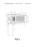
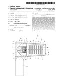
[0009] FIG. 1 is a vertical cross-sectional view of a dryer according to a preferred embodiment of the present invention.
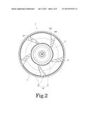
[0010] FIG. 2 is a cross-sectional view of the dryer taken along a plane indicated by line A-A in FIG. 1 and as viewed from a direction indicated by arrows A.
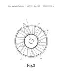
[0011] FIG. 3 is a cross-sectional view of the dryer taken along a plane indicated by line B-B in FIG. 1 and as viewed from a direction indicated by arrows B.
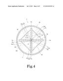
[0012] FIG. 4 is a cross-sectional view of the dryer taken along a plane indicated by line C-C in FIG. 1 and as viewed from a direction indicated by arrows C.
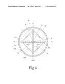
[0013] FIG. 5 is a cross-sectional view of a dryer according to an example modification of the above preferred embodiment of the present invention taken at the same position and as viewed from the same direction as the cross-sectional view of FIG. 4.
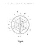
[0014] FIG. 6 is a cross-sectional view of a dryer according to an example modification of the above preferred embodiment of the present invention taken at the same position and as viewed from the same direction as the cross-sectional view of FIG. 4.
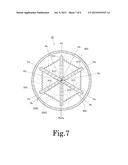
[0015] FIG. 7 is a cross-sectional view of a dryer according to an example modification of the above preferred embodiment of the present invention taken at the same position and as viewed from the same direction as the cross-sectional view of FIG. 4.
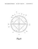
[0016] FIG. 8 is a cross-sectional view of a dryer according to an example modification of the above preferred embodiment of the present invention taken at the same position and as viewed from the same direction as the cross-sectional view of FIG. 4.
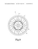
[0017] FIG. 9 is a cross-sectional view of a dryer according to an example modification of the above preferred embodiment of the present invention taken at the same position and as viewed from the same direction as the cross-sectional view of FIG. 4.
DETAILED DESCRIPTION OF THE PREFERRED EMBODIMENTS
[0018] Hereinafter, preferred embodiments of the present invention will be described with reference to the accompanying drawings. It is assumed herein that a "blowing axis" is defined along a direction in which a dryer blows an airflow. It is also assumed herein that a direction parallel to or substantially parallel to the blowing axis is referred to by the term "axial direction", "axial", or "axially", that directions perpendicular or substantially perpendicular to the blowing axis are referred to by the term "radial direction", "radial", or "radially", and that a direction along a circular arc centered on the blowing axis is referred to by the term "circumferential direction", "circumferential", or "circumferentially". It is also assumed herein that a downstream side and an upstream side (with respect to the airflow) along the blowing axis are defined as a front side and a rear side, respectively. The shape of each member or portion and relative positions of different members or portions will be described based on the above assumptions. It should be noted, however, that the above definitions of a front-rear direction and the front and rear sides are not meant to restrict in any way the orientation of a dryer according to any preferred embodiment of the present invention when in use.
[0019] FIG. 1 is a vertical cross-sectional view of a dryer 1 according to a preferred embodiment of the present invention. FIG. 2 is a cross-sectional view of the dryer 1 taken along a plane indicated by line A-A in FIG. 1 and as viewed from a direction indicated by arrows A. FIG. 3 is a cross-sectional view of the dryer 1 taken along a plane indicated by line B-B in FIG. 1 and as viewed from a direction indicated by arrows B. FIG. 4 is a cross-sectional view of the dryer 1 taken along a plane indicated by line C-C in FIG. 1 and as viewed from a direction indicated by arrows C.
[0020] The dryer 1 is an apparatus designed to send hot air forward in the axial direction by rotating an impeller 20 through power of a motor 30. The dryer 1 is preferably used, for example, as a household hair dryer or a hair dryer for professional use to dry hair. Note, however, that dryers according to preferred embodiments of the present invention may be dryers designed to dry or heat objects other than hair, e.g., industrial dryers, heat guns, etc. Referring to FIG. 1, the dryer 1 according to the present preferred embodiment preferably includes a housing 10, the impeller 20, the motor 30, a flow control member 40, a heater support portion 50, and a heater 60. The impeller 20 is an axial flow impeller.
[0021] The housing 10 preferably includes a tubular portion 11 and a handle portion 12. The tubular portion 11 is arranged to surround a blowing axis 9, and extends in the axial direction to assume a cylindrical or substantially cylindrical shape. The handle portion 12 extends radially outward from a surface of the tubular portion 11. The tubular portion 11 includes an air inlet at an axially rearward end thereof. A filter 711 is preferably attached at the air inlet 71 to prevent dust from intruding into an interior of the tubular portion 11. In addition, the tubular portion 11 includes an air outlet 72 at an axially forward end thereof.
[0022] Referring to FIGS. 2 to 4, the tubular portion 11 according to the present preferred embodiment is perfectly circular or substantially perfectly circular in a cross-section taken along any plane perpendicular to the blowing axis 9. Note, however, that the tubular portion 11 may alternatively be arranged to have any other desirable shape, such as, for example, an ellipse, a quadrilateral, etc., in the cross-section taken along any plane perpendicular to the blowing axis 9. In addition, according to the present preferred embodiment, the diameter of the tubular portion 11 is arranged to decrease in an axially forward direction. Note, however, that the diameter of the tubular portion 11 may alternatively be arranged to be constant or to increase in the axially forward direction. Also note that the shape of cross-sections of the tubular portion 11 taken along planes perpendicular to the blowing axis 9 may be arranged to vary as the cross-section moves in the axially forward direction.
[0023] The impeller 20 is preferably a member configured to rotate about the blowing axis 9 to generate an air current traveling axially forward. The impeller 20 is located inside the tubular portion 11. Referring to FIGS. 1 and 2, the impeller 20 according to the present preferred embodiment includes a cup portion 21 arranged at a center thereof, and a plurality of blades 22 extending radially outward from the cup portion 21. The cup portion 21 is fixed to a shaft 31 of the motor 30. The plurality of blades 22 are positioned in a circumferential direction radially outside of the cup portion 21. Each blade 22 preferably extends obliquely with respect to both the axial direction and the circumferential direction.
[0024] Here, of both circumferential edges of each blade 22, a front-side edge and a rear-side edge with respect to a rotation direction of the impeller 20 are defined as a first edge 221 and a second edge 222, respectively. In this impeller 20, the second edge 222 is arranged axially forward of the first edge 221. Accordingly, once the impeller 20 starts rotating, an airflow which travels axially forward from behind the impeller 20 is generated.
[0025] The impeller 20 according to the present preferred embodiment is preferably a single monolithic resin member obtained by an injection molding process. Note, however, that the impeller 20 may alternatively be defined by a plurality of members. For example, the cup portion 21 and the plurality of blades 22 may be defined by separate members. Also note that the impeller 20 may not necessarily be made of a resin.
[0026] The motor 30 is a mechanism arranged to supply, to the impeller 20, power for rotation. According to the present preferred embodiment, the motor 30 is arranged axially forward of the impeller 20. Note, however, that the motor 30 may alternatively be arranged axially rearward of the impeller 20. The motor 30 includes the shaft 31, which extends along the blowing axis 9. Once the motor 30 is driven, a torque centered on the blowing axis 9 is produced through magnetic interaction between, for example, coils and a magnet located inside the motor 30. The shaft 31 of the motor 30 is thus caused to rotate about the blowing axis 9.
[0027] The motor 30 according to the present preferred embodiment is preferably a brushless DC motor. The brushless DC motor has a longer life than a comparable brushed motor because the brushless DC motor is free from deterioration in performance which is caused by a brush wearing out. In addition, it is easier to change the speed of the brushless DC motor than the speed of an AC motor, and it is also easier to reduce the power consumption of the brushless DC motor than the power consumption of the AC motor. Note, however, that a motor according to a preferred embodiment of the present invention may be any desirable motor, such as, for example, a brushed motor or an AC motor instead of a brushless DC motor.
[0028] The flow control member 40 is preferably arranged axially forward of the impeller 20 and axially rearward of the heater support portion 50 inside the tubular portion 11. The flow control member 40 preferably includes a plurality of stationary vanes 41 extending radially or substantially radially. The stationary vanes 41 are positioned in the circumferential direction radially outside of the motor 30. The airflow generated by the impeller 20 is sent toward the heater support portion 50 through gaps between the stationary vanes 41.
[0029] The heater support portion 50 is arranged axially forward of the impeller 20, the motor 30, and the flow control member 40 inside the tubular portion 11. The heater support portion 50 preferably includes four plate-shaped portions 51 extending in a radial manner with the blowing axis 9 as a center. Referring to FIG. 4, each of the four plate-shaped portions 51 preferably extends radially outward from the blowing axis 9 in a straight or substantially straight line in a cross-section perpendicular or substantially perpendicular to the blowing axis 9.
[0030] According to the present preferred embodiment, the heater support portion 50 is preferably defined by a combination of two support plates 52. The two support plates 52 are preferably fixed to each other by, for example, fitting cuts defined in both the support plates 52 to each other. Each support plate 52 preferably includes a pair of plate-shaped portions 51 each of which extends in a mutually opposite direction from the blowing axis 9. Thus, the four plate-shaped portions 51 are preferably arranged around the blowing axis 9 at angular intervals of about 90 degrees, for example. A reduction in the number of parts of the heater support portion 50 can be achieved by combining the support plates 52 each of which includes the pair of plate-shaped portions 51 as described above. Note, however, that each of the plate-shaped portions 51 may be defined by a separate member.
[0031] The heater 60 is a heat source used to heat the airflow generated by the impeller 20. A heating wire, such as a nichrome wire, which generates heat when energized, for example, is preferably used as the heater 60. The heater 60 is located inside the tubular portion 11, and is supported by the heater support portion 50. Specifically, the heater 60 is preferably retained in cutouts defined in the plate-shaped portions 51. Note that the heater 60 may alternatively be wrapped around radially outer edges of the plate-shaped portions 51 such that the heater 60 is placed across the four plate-shaped portions 51.
[0032] Once a power switch of the dryer 1 is turned on, electric current is supplied to both the motor 30 and the heater 60. The motor 30 is thus activated to cause the shaft 31 and the impeller 20 fixed to the shaft 31 to rotate about the blowing axis 9. As a result, gas is accelerated by the blades 22, and an airflow traveling axially forward is generated inside the tubular portion 11. The airflow, which is sent forward from the impeller 20 through the flow control member 40, is heated by heat of the heater 60. Then, the heated wind is blown forward out of the tubular portion 11 through the air outlet 72.
[0033] The dryer 1 has a structure designed to reduce noise caused by interference of the airflow generated by the impeller 20 with the heater support portion 50. This structure will be described below with reference to FIG. 4. Note that, in FIG. 4, the impeller 20 as viewed from the front side in the axial direction is represented by broken lines.
[0034] Referring to FIG. 4, the number of blades 22 of the impeller 20 according to the present preferred embodiment is preferably five, for example. Accordingly, the number of second edges 222 included in the impeller 20 is also preferably five, for example. Gas which is accelerated by each blade 22 is concentrated in a vicinity of a radially outer end 223 of the second edge 222 of the blade 22, and is sent axially forward from the radially outer end 223. That is, the volume of air which is sent axially forward from the vicinity of the radially outer end 223 of the second edge 222 is greater than the volume of air which is sent axially forward from any other portion of the blade 22.
[0035] Here, referring to FIG. 4, the circumferential position of an axially rearward end of each plate-shaped portion 51 is denoted by reference symbol "Pa", and the circumferential position of the radially outer end 223 of the second edge 222 of each blade 22 is denoted by reference symbol "Pb". In this dryer 1, the circumferential positions Pa and the circumferential positions Pb do not overlap with each other at more than one position at any given time when viewed in the axial direction. That is, regardless of the rotational position of the impeller 20, the number of positions at which the circumferential positions Pa and the circumferential positions Pb overlap with each other is always one or less. Therefore, an airflow which is sent forward from the vicinity of the radially outer end 223 of the second edge 222 of each blade 22 does not strike two or more of axially rearward edges of the plate-shaped portions 51 at the same time. Thus, noise caused by interference of the airflow with any plate-shaped portion 51 is significantly reduced or prevented.
[0036] In addition, referring to FIG. 4, the circumferential position of a portion of the second edge 222 of each blade 22, the portion being radially outward of a middle of the second edge 222 of the blade 22, is denoted by reference symbol "Pb2". Then, in this dryer 1, the circumferential positions Pa and the circumferential positions Pb2 do not overlap with each other at more than one position at any given time when viewed in the axial direction. That is, regardless of the rotational position of the impeller 20, the number of positions at which the circumferential positions Pa and the circumferential positions Pb2 overlap with each other is always one or less. Therefore, not only the airflow which is sent forward from the vicinity of the radially outer end 223 of the second edge 222 of each blade 22, but also an airflow which is sent forward from the portion of the second edge 222 of each blade 22, the portion being radially outward of the middle of the second edge 222 of the blade 22, does not strike two or more of the axially rearward edges of the plate-shaped portions 51 at the same time. Thus, the noise caused by the interference of the airflow with any plate-shaped portion 51 is further reduced or prevented.
[0037] It is assumed that Na denotes the number of plate-shaped portions 51 included in the heater support portion 50. Then, Na is preferably four according to the present preferred embodiment, for example. When Na is an even number, a pair of plate-shaped portions 51 can be defined by a single support plate 52 as described above. However, if Na were two, the two plate-shaped portions 51 adjacent to each other would be arranged at angular intervals of 180 degrees, and it would be considerably difficult to place the heater 60 across the adjacent plate-shaped portions 51. Accordingly, according to the present preferred embodiment, Na is preferably four as this is the smallest number that allows the heater 60 to be easily supported by the support plates 52.
[0038] Meanwhile, it is assumed that Nb denotes the number of blades 22 included in the impeller 20. Then, Nb is preferably five according to the present preferred embodiment, for example. Thus, the number Na of plate-shaped portions 51 included in the heater support portion 50 and the number Nb of blades 22 included in the impeller 20 do not possess common denominators (except for one) and are not divisible with respect to one another. In addition, both the four plate-shaped portions 51 and the five blades 22 are arranged at regular intervals in the circumferential direction. If Na and Nb had a common divisor other than one, the aforementioned circumferential positions Pa and the aforementioned circumferential positions Pb2 would overlap with each other at more than one position at some moment. In addition, the total of areas over which the blades 22 and the plate-shaped portions 51 overlap with each other when viewed in the axial direction at a moment when the blades 22 and the plate-shaped portions 51 overlap with each other most extensively would be large. When Na and Nb do not possess common denominators and are not divisible with respect to one another as in the present preferred embodiment, the total of the areas over which the blades 22 and the plate-shaped portions 51 overlap with each other when viewed in the axial direction at the moment when the blades 22 and the plate-shaped portions 51 overlap with each other most extensively is reduced. As a result, the noise caused by the interference of the airflow with any plate-shaped portion 51 is further reduced or prevented.
[0039] The dryer 1 according to the present preferred embodiment preferably includes the flow control member 40 between the impeller 20 and the heater support portion 50. Accordingly, the airflow generated by the impeller 20 is subjected to flow control by the stationary vanes 41 of the flow control member 40, and is sent toward the heater support portion 50. Thus, the noise caused by the interference of the airflow with the heater support portion 50 is further reduced.
[0040] Here, as noted above, Pb denotes the circumferential position of the radially outer end 223 of the second edge 222 of each blade 22. Referring to FIG. 3, it is also assumed that Pc denotes the circumferential position of an axially rearward edge of each stationary vane 41. In this dryer 1, the circumferential positions Pb and the circumferential positions Pc do not overlap with each other at more than one position at any given time when viewed in the axial direction. That is, regardless of the rotational position of the impeller 20, the number of positions at which the circumferential positions Pb and the circumferential positions Pc overlap with each other is always one or less. Therefore, an airflow which is sent forward from the vicinity of the radially outer end 223 of the second edge 222 of each blade 22 does not strike two or more of the axially rearward edges of the stationary vanes 41 at the same time. Thus, noise caused by interference of the airflow with any stationary vane 41 is reduced.
[0041] It is also assumed that Nc denotes the number of stationary vanes 41 included in the flow control member 40. Then, Nc is preferably twelve according to the present preferred embodiment. Therefore, the number Nb of blades 22 included in the impeller 20 and the number Nc of stationary vanes 41 included in the flow control member 40 do not possess common denominators (except for one) and are not divisible with respect to one another. In addition, the twelve stationary vanes 41 are arranged at regular intervals in the circumferential direction. If Nb and Nc had a common divisor other than one, the aforementioned circumferential positions Pb and the aforementioned circumferential positions Pc would overlap with each other at more than one position at some moment. In addition, the total of areas over which the blades 22 and the stationary vanes 41 overlap with each other when viewed in the axial direction at a moment when the blades 22 and the stationary vanes 41 overlap with each other most extensively would be large. When Nb and Nc do not possess common denominators and are not divisible with respect to one another as in the present preferred embodiment, the total of the areas over which the blades 22 and the stationary vanes 41 overlap with each other when viewed in the axial direction at the moment when the blades and the stationary vanes 41 overlap with each other most extensively is reduced.
[0042] In addition, according to the present preferred embodiment, the number Nc of stationary vanes 41, i.e., twelve, is preferably exactly three times the number Na of plate-shaped portions 51, i.e., four. When Nc is an integral multiple of Na as in the present preferred embodiment, it is possible to arrange each of all the plate-shaped portions 51 to overlap with one of the stationary vanes 41 when viewed in the axial direction. This leads to a reduction in the combined area of the stationary vanes 41 and the plate-shaped portions 51 when viewed in the axial direction. Thus, noise caused by interference of the airflow with the stationary vanes 41 and the plate-shaped portions 51 is further reduced or prevented.
[0043] While a preferred embodiment of the present invention has been described above, it will be understood that the present invention is not limited to the above-described preferred embodiment.
[0044] FIG. 5 is a cross-sectional view of a dryer 1A according to an example modification of the above-described preferred embodiment taken at the same position and as viewed from the same direction as the cross-sectional view of FIG. 4. In FIG. 5, an impeller 20A as viewed from the front side in the axial direction is represented by broken lines. In the modification illustrated in FIG. 5, the number Na of plate-shaped portions 51A included in a heater support portion 50A is preferably four, for example. Meanwhile, the number Nb of blades 22A included in the impeller 20A is preferably seven, for example. Therefore, Na and Nb do not possess common denominators (except for one) and are not divisible with respect to one another. In addition, both the four plate-shaped portions 51A and the seven blades 22A are arranged at regular intervals in the circumferential direction. Thus, the total of areas over which the blades 22A and the plate-shaped portions 51A overlap with each other when viewed in the axial direction at a moment when the blades 22A and the plate-shaped portions 51A overlap with each other most extensively is reduced.
[0045] In addition, also in the modification illustrated in FIG. 5, the circumferential positions Pa of axially rearward ends of the plate-shaped portions 51A and the circumferential positions Pb of radially outer ends 223A of second edges 222A of the blades 22A do not overlap with each other at more than one position at any given time when viewed in the axial direction. That is, regardless of the rotational position of the impeller 20A, the number of positions at which the circumferential positions Pa and the circumferential positions Pb overlap with each other is always one or less. Therefore, an airflow which is sent forward from a vicinity of the radially outer end 223A of the second edge 222A of each blade 22A does not strike two or more of axially rearward edges of the plate-shaped portions 51A at the same time. Thus, noise caused by interference of the airflow with any plate-shaped portion 51A is significantly reduced or prevented.
[0046] FIG. 6 is a cross-sectional view of a dryer 1B according to another example modification of the above-described preferred embodiment taken at the same position and as viewed from the same direction as the cross-sectional view of FIG. 4. In FIG. 6, an impeller 20B as viewed from the front side in the axial direction is represented by broken lines. In the modification illustrated in FIG. 6, the number Na of plate-shaped portions 51B included in a heater support portion 50B is preferably six, for example. Meanwhile, the number Nb of blades 22B included in the impeller 20B is preferably five, for example. Therefore, Na and Nb are relatively do not possess common denominators (except for one) and are not divisible with respect to one another. In addition, both the six plate-shaped portions 51B and the five blades 22B are arranged at regular intervals in the circumferential direction. Thus, the total of areas over which the blades 22B and the plate-shaped portions 51B overlap with each other when viewed in the axial direction at a moment when the blades 22B and the plate-shaped portions 51B overlap with each other most extensively is significantly reduced or prevented.
[0047] In addition, also in the modification illustrated in FIG. 6, the circumferential positions Pa of axially rearward ends of the plate-shaped portions 51B and the circumferential positions Pb of radially outer ends 223B of second edges 222B of the blades 22B do not overlap with each other at more than one position at any given time when viewed in the axial direction. That is, regardless of the rotational position of the impeller 20B, the number of positions at which the circumferential positions Pa and the circumferential positions Pb overlap with each other is always one or less. Therefore, an airflow which is sent forward from a vicinity of the radially outer end 223B of the second edge 222B of each blade 22B does not strike two or more of axially rearward edges of the plate-shaped portions 51B at the same time. Thus, noise caused by interference of the airflow with any plate-shaped portion 51B is significantly reduced or prevented.
[0048] FIG. 7 is a cross-sectional view of a dryer 1C according to yet another example modification of the above-described preferred embodiment taken at the same position and as viewed from the same direction as the cross-sectional view of FIG. 4. In FIG. 7, an impeller 20C as viewed from the front side in the axial direction is represented by broken lines. In the modification illustrated in FIG. 7, the number Na of plate-shaped portions 51C included in a heater support portion 50C is preferably six, for example. Meanwhile, the number Nb of blades 22C included in the impeller 20C is preferably seven, for example. Therefore, Na and Nb are relatively do not possess common denominators (except for one) and are not divisible with respect to one another. In addition, both the six plate-shaped portions 51C and the seven blades 22C are arranged at regular intervals in the circumferential direction. Thus, the total of areas over which the blades 22C and the plate-shaped portions 51C overlap with each other when viewed in the axial direction at a moment when the blades 22C and the plate-shaped portions 51C overlap with each other most extensively is reduced.
[0049] In addition, also in the modification illustrated in FIG. 7, the circumferential positions Pa of axially rearward ends of the plate-shaped portions 51C and the circumferential positions Pb of radially outer ends 223C of second edges 222C of the blades 22C do not overlap with each other at more than one position at any given time when viewed in the axial direction. That is, regardless of the rotational position of the impeller 20C, the number of positions at which the circumferential positions Pa and the circumferential positions Pb overlap with each other is always one or less. Therefore, an airflow which is sent forward from a vicinity of the radially outer end 223C of the second edge 222C of each blade 22C does not strike two or more of axially rearward edges of the plate-shaped portions 51C at the same time. Thus, noise caused by interference of the airflow with any plate-shaped portion 51C is significantly reduced or prevented.
[0050] Note that, when the number of plate-shaped portions is six as it preferably is in each of the modifications illustrated in FIGS. 6 and 7, the angular interval between adjacent ones of the plate-shaped portions is smaller than in the case where the number of plate-shaped portions is four, and therefore, a heater can be more stably supported across the adjacent plate-shaped portions.
[0051] FIG. 8 is a cross-sectional view of a dryer 1D according to yet another example modification of the above-described preferred embodiment taken at the same position and as viewed from the same direction as the cross-sectional view of FIG. 4. In the modification illustrated in FIG. 8, an impeller 20D preferably includes six blades 22D, for example. However, the six blades 22D are divided into three pairs of two blades, and the two blades 22D in each pair are arranged closer to each other in the circumferential direction. Therefore, in the modification illustrated in FIG. 8, spaces defined between circumferentially adjacent ones of the blades 22D include smaller spaces and larger spaces. That is, the six blades 22D are arranged at irregular intervals in the circumferential direction.
[0052] Also in the modification illustrated in FIG. 8, the circumferential positions Pa of axially rearward ends of plate-shaped portions 51D and the circumferential positions Pb of radially outer ends 223D of second edges 222D of the blades 22D preferably do not overlap with each other at more than one position at any given time when viewed in the axial direction. That is, regardless of the rotational position of the impeller 20D, the number of positions at which the circumferential positions Pa and the circumferential positions Pb overlap with each other is always one or less. Therefore, an airflow which is sent forward from a vicinity of the radially outer end 223D of the second edge 222D of each blade 22D does not strike two or more of axially rearward edges of the plate-shaped portions 51D at the same time. Thus, noise caused by interference of the airflow with any plate-shaped portion 51D is preferably reduced.
[0053] Note that a pattern in which a plurality of blades are arranged at irregular intervals in the circumferential direction is not limited to the pattern according to the modification illustrated in FIG. 8. Smaller spaces between circumferentially adjacent ones of the blades and larger spaces between circumferentially adjacent ones of the blades may be positioned in a pattern different from that of the modification illustrated in FIG. 8. Also note that circumferential spaces between a plurality of blades of an impeller may all be different in width.
[0054] FIG. 9 is a cross-sectional view of a dryer 1E according to yet another example modification of the above-described preferred embodiment taken at the same position and as viewed from the same direction as the cross-sectional view of FIG. 4. Although the flow control member is not shown in each of FIGS. 4 to 8, a flow control member 40E is depicted axially behind a heater support portion 50E in FIG. 9. In the modification illustrated in FIG. 9, the heater support portion 50E preferably includes four plate-shaped portions 51E, and the flow control member 40E preferably includes twelve stationary vanes 41E, for example. Thus, the number of stationary vanes 41E is exactly three times the number of plate-shaped portions 51E. In addition, in the modification illustrated in FIG. 9, an axially rearward edge of each of all the plate-shaped portions 51E overlaps at least in part with an axially forward edge 411E of one of the stationary vanes 41E. This leads to a reduction in the combined area of the axially forward edges 411E of the stationary vanes 41E and the plate-shaped portions 51E when viewed in the axial direction. In addition, the likelihood that an airflow which is sent toward the heater support portion 50E through gaps between the stationary vanes 41E will strike any plate-shaped portion 51E is reduced. Thus, noise caused by interference of the airflow with the stationary vanes 41E and the plate-shaped portions 51E can be further reduced.
[0055] Note that, although the stationary vanes are arranged at regular intervals in the circumferential direction in each of the above-described preferred embodiment and the modifications thereof, the stationary vanes may alternatively be arranged at irregular intervals in the circumferential direction. Also note that the flow control member may be omitted so that the heater support portion will be arranged axially forward of the impeller without the flow control member intervening therebetween. In this case, the airflow generated by the impeller will strike the heater support portion without being subjected to flow control. Therefore, in this case, it is more important to arrange the blades and the plate-shaped portions in a positional relationship according to any of the above-described preferred embodiment and the modifications thereof, in order to reduce noise caused by interference of the airflow with the heater support portion.
[0056] Each blade of the impeller according to each of the above-described preferred embodiment and the modifications thereof preferably is a so-called swept-forward blade, which is curved forward with respect to the rotation direction of the impeller with increasing distance from the blowing axis. Note, however, that an impeller according to a preferred embodiment of the present invention may include so-called sweptback blades, each of which is curved rearward with respect to the rotation direction of the impeller with increasing distance from the blowing axis. Also in the case of the sweptback blades, assuming that, of both circumferential edges of each blade, a front-side edge and a rear-side edge with respect to the rotation direction of the impeller are defined as a first edge and a second edge, respectively, the second edge is arranged axially forward of the first edge.
[0057] In each of the above-described preferred embodiments and the modifications thereof, the impeller is configured to rotate about the blowing axis, and the plate-shaped portions of the heater support portion are extending in the radial manner with the blowing axis as the center. Note, however, that a rotation axis of the impeller and a central axis of the heater support portion may not necessarily completely coincide with each other. That is, as long as the blowing axis is defined along the central axis of the heater support portion, the rotation axis of the impeller may be extending parallel or substantially parallel to the blowing axis at a position displaced from the blowing axis.
[0058] Preferred embodiments of the present invention and modifications thereof are applicable, for example, to dryers, blowers, heat guns, etc.
[0059] Note that the detailed shape of any member of the dryer may be different from the shape thereof as illustrated in the accompanying drawings of the present application. Also note that features of the above-described preferred embodiment and the modifications thereof may be combined appropriately as long as no conflict arises.
[0060] While preferred embodiments of the present invention have been described above, it is to be understood that variations and modifications will be apparent to those skilled in the art without departing from the scope and spirit of the present invention. The scope of the present invention, therefore, is to be determined solely by the following claims.
User Contributions:
Comment about this patent or add new information about this topic:
Images included with this patent application:
 |  |
 |  |
 |  |
 |  |
 |  |
| New patent applications in this class: | |
| Date | Title |
|---|---|
| 2022-09-08 | Shrub rose plant named 'vlr003' |
| 2022-08-25 | Cherry tree named 'v84031' |
| 2022-08-25 | Miniature rose plant named 'poulty026' |
| 2022-08-25 | Information processing system and information processing method |
| 2022-08-25 | Data reassembly method and apparatus |
| New patent applications from these inventors: | |
| Date | Title |
|---|---|
| 2022-01-06 | Rotor, method for manufacturing rotor, and motor |
| 2021-02-04 | Motor |
| 2021-02-04 | Motor |
| 2015-07-09 | Dryer |
| 2012-02-02 | Axial fan and slide mold |