Patent application title: DRYER APPLIANCE
Inventors:
Ashutosh Kulkarni (Bangalore, IN)
Assignees:
GENERAL ELECTRIC COMPANY
IPC8 Class: AD06F5804FI
USPC Class:
Class name:
Publication date: 2015-07-09
Patent application number: 20150191862
Abstract:
Dryer appliances are provided. A dryer appliance may include a cabinet,
and a drum positioned within the cabinet, the drum including a generally
cylindrical inner surface and a rear wall and defining a chamber for
receipt of articles for drying, the drum generally fixed within the
cabinet. The dryer assembly may further include a baffle assembly
rotatable within the chamber, the baffle assembly including a baffle, a
motor, and an arm connecting the baffle to the motor. Alternatively, the
dryer assembly may further include at least one sensor disposed on the
inner surface of the drum, the sensor configured to measure at least one
of temperature or humidity within the chamber. Alternatively, the dryer
assembly may further include a baffle including a body and a contact tip,
the contact tip in contact with the inner surface of the drum, the
contact tip formed from a felt.Claims:
1. A dryer appliance, comprising: a cabinet; a drum positioned within the
cabinet, the drum comprising a generally cylindrical inner surface and a
rear wall and defining a chamber for receipt of articles for drying, the
drum generally fixed within the cabinet; and a baffle assembly rotatable
within the chamber, the baffle assembly comprising a baffle, a motor, and
an arm connecting the baffle to the motor.
2. The dryer appliance of claim 1, wherein the baffle assembly is simply supported within the chamber.
3. The dryer appliance of claim 1, wherein the baffle assembly is cantilevered within the chamber.
4. The dryer appliance of claim 1, wherein at least a portion of the arm extends radially within the chamber.
5. The dryer appliance of claim 1, wherein the arm extends axially within the chamber.
6. The dryer appliance of claim 1, wherein the baffle assembly is rotatable about a longitudinal axis of the drum.
7. The dryer appliance of claim 1, further comprising at least one sensor disposed on the inner surface of the drum, the sensor configured to measure at least one of temperature, humidity or moisture content within the chamber.
8. The dryer appliance of claim 1, wherein the baffle comprises a body and a contact tip, the contact tip extending from the body and in contact with the inner surface of the drum.
9. The dryer appliance of claim 1, wherein the baffle assembly further comprises a spring mechanism biasing the baffle towards the inner surface of the drum.
10. A dryer appliance, comprising: a cabinet; a drum positioned within the cabinet, the drum comprising a generally cylindrical inner surface and a rear wall and defining a chamber for receipt of articles for drying, the drum generally fixed within the cabinet; a baffle assembly rotatable within the chamber; and at least one sensor disposed on the inner surface of the drum, the sensor configured to measure at least one of temperature, humidity or moisture content within the chamber.
11. The dryer appliance of claim 10, wherein the at least one sensor is configured to measure temperature, humidity and moisture content within the chamber.
12. The dryer appliance of claim 10, wherein the at least one sensor is a plurality of sensors.
13. A dryer appliance, comprising: a cabinet; a drum positioned within the cabinet, the drum comprising a generally cylindrical inner surface and a rear wall and defining a chamber for receipt of articles for drying, the drum generally fixed within the cabinet; and a baffle assembly rotatable within the chamber, the baffle assembly comprising a baffle and a motor, the baffle comprising a body and a contact tip, the contact tip in contact with the inner surface of the drum, the contact tip formed from one of a felt or a rubber.
14. The dryer appliance of claim 13, wherein the contact tip extends from the body.
15. The dryer appliance of claim 13, wherein the baffle further comprises a spring mechanism biasing the tip towards the inner surface of the drum.
16. The dryer appliance of claim 13, wherein the baffle further comprises a contact arm extending from the body.
17. The dryer appliance of claim 16, wherein the contact tip extends from the contact arm.
18. The dryer appliance of claim 16, wherein the contact arm is a plurality of contact arms.
19. The dryer appliance of claim 18, wherein the baffle further comprises a spring mechanism biasing the plurality of contact arms towards each other.
20. The dryer appliance of claim 13, wherein the baffle further comprises a compliant member mounted to the body and in contact with the inner surface of the drum.
Description:
FIELD OF THE INVENTION
[0001] The present subject matter relates generally to dryer appliances, such as dryer appliances with fixed drums.
BACKGROUND OF THE INVENTION
[0002] Dryer appliances generally include a cabinet with a drum mounted therein. Dryer appliances also generally include a heater assembly that passes heated air through the chamber of the drum in order to dry moisture laden articles disposed within the chamber.
[0003] In many dryer appliances, a motor rotates the drum during operation of the dryer appliance, e.g., to tumble articles located within a chamber defined by the drum. Alternatively, however, dryer appliances with fixed drums have been utilized. Typically, a dryer appliance with a fixed drum utilizes movable components within the dryer to tumble the articles within the chamber. In known dryer appliances, baffles extend from a rotating disk which is rotatably mounted to a motor. Rotation of the disk rotates the baffles, which contact and tumble the articles within the chamber.
[0004] However, improvements in the dryer appliance art are desired. For example, in many dryer appliances, sensors are located in the doors or other locations, such as fixed near the rear of the dryer appliance or on the baffles, which result in little or no contact with articles disposed in the chambers of the dryer appliances. Further, in many fixed drum dryer appliances, the baffles are relatively ineffective and articles may become caught between the baffles and inner surfaces of the drums.
[0005] Accordingly, improved dryer appliances are desired in the art. For example, fixed drum dryer appliances with improved baffle assemblies and improved sensing capabilities would be advantageous.
BRIEF DESCRIPTION OF THE INVENTION
[0006] In one embodiment, a dryer appliance is disclosed. The dryer appliance includes a cabinet, and a drum positioned within the cabinet, the drum including a generally cylindrical inner surface and a rear wall and defining a chamber for receipt of articles for drying. The drum is generally fixed within the cabinet. The dryer assembly further includes a baffle assembly rotatable within the chamber, the baffle assembly including a baffle, a motor, and an arm connecting the baffle to the motor.
[0007] In another embodiment, a dryer appliance is disclosed. The dryer appliance includes a cabinet, and a drum positioned within the cabinet, the drum including a generally cylindrical inner surface and a rear wall and defining a chamber for receipt of articles for drying, the drum generally fixed within the cabinet. The dryer appliance further includes a baffle assembly rotatable within the chamber, and at least one sensor disposed on the inner surface of the drum, the sensor configured to measure at least one of temperature, humidity or moisture content within the chamber.
[0008] In another embodiment, a dryer appliance is disclosed. The dryer appliance includes a cabinet, and a drum positioned within the cabinet, the drum including a generally cylindrical inner surface and a rear wall and defining a chamber for receipt of articles for drying. The drum is generally fixed within the cabinet. The dryer appliance further includes a baffle assembly rotatable within the chamber, the baffle assembly including a baffle and a motor, the baffle including a body and a contact tip, the contact tip in contact with the inner surface of the drum, the contact tip formed from one of a felt or a rubber.
[0009] These and other features, aspects and advantages of the present invention will become better understood with reference to the following description and appended claims. The accompanying drawings, which are incorporated in and constitute a part of this specification, illustrate embodiments of the invention and, together with the description, serve to explain the principles of the invention.
BRIEF DESCRIPTION OF THE DRAWINGS
[0010] A full and enabling disclosure of the present invention, including the best mode thereof, directed to one of ordinary skill in the art, is set forth in the specification, which makes reference to the appended figures.
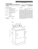
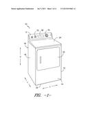
[0011] FIG. 1 provides a perspective view of a dryer appliance in accordance with one embodiment of the present disclosure.
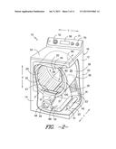
[0012] FIG. 2 provides a perspective view of the dryer appliance of FIG. 1 with portions of a cabinet of the dryer appliance removed to reveal certain components of the dryer appliance.
[0013] FIG. 3 provides a side cross-sectional schematic view of a dryer appliance in accordance with one embodiment of the present disclosure;
[0014] FIG. 4 provides a side cross-sectional schematic view of a dryer appliance in accordance with another embodiment of the present disclosure;
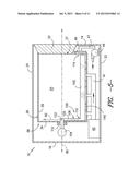
[0015] FIG. 5 provides a side cross-sectional schematic view of a dryer appliance in accordance with another embodiment of the present disclosure;
[0016] FIG. 6 provides a side cross-sectional schematic view of a dryer appliance in accordance with another embodiment of the present disclosure;
[0017] FIG. 7 provides a side cross-sectional schematic view of a dryer appliance in accordance with another embodiment of the present disclosure;
[0018] FIG. 8 provides a perspective internal view of a drum for a dryer appliance in accordance with one embodiment of the present disclosure;
[0019] FIG. 9 provides a perspective internal view of a drum for a dryer appliance in accordance with another embodiment of the present disclosure;
[0020] FIG. 10 provides a perspective internal view of a drum for a dryer appliance in accordance with another embodiment of the present disclosure;
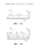
[0021] FIG. 11 provides a side view of a baffle in accordance with one embodiment of the present disclosure;
[0022] FIG. 12 provides a side view of a baffle in accordance with another embodiment of the present disclosure;
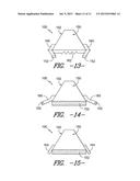
[0023] FIG. 13 provides a front view of a baffle in accordance with one embodiment of the present disclosure;
[0024] FIG. 14 provides a front view of a baffle in accordance with another embodiment of the present disclosure; and
[0025] FIG. 15 provides a front view of a baffle in accordance with another embodiment of the present disclosure.
DETAILED DESCRIPTION
[0026] Reference now will be made in detail to embodiments of the invention, one or more examples of which are illustrated in the drawings. Each example is provided by way of explanation of the invention, not limitation of the invention. In fact, it will be apparent to those skilled in the art that various modifications and variations can be made in the present invention without departing from the scope or spirit of the invention. For instance, features illustrated or described as part of one embodiment can be used with another embodiment to yield a still further embodiment. Thus, it is intended that the present invention covers such modifications and variations as come within the scope of the appended claims and their equivalents.
[0027] FIG. 1 illustrates a dryer appliance 10 according to an exemplary embodiment of the present subject matter. FIG. 2 provides another perspective view of dryer appliance 10 with a portion of a cabinet or housing 12 of dryer appliance 10 removed in order to show certain components of dryer appliance 10. While described in the context of a specific embodiment of dryer appliance 10, using the teachings disclosed herein it will be understood that dryer appliance 10 is provided by way of example only. Other dryer appliances having different appearances and different features may also be utilized with the present subject matter as well. Dryer appliance 10 defines a vertical direction V, a lateral direction L, and a transverse direction T. The vertical direction V, lateral direction L, and transverse direction T are mutually perpendicular and form and orthogonal direction system.
[0028] Cabinet 12 includes a front panel 14, a rear panel 16, a pair of side panels 18 and 20 spaced apart from each other by front and rear panels 14 and 16, a bottom panel 22, and a top cover 24. Within cabinet 12 is a fixedly mounted drum or container 26. Drum 26 is fixed within the cabinet 12, such that it is generally stationary and non-rotational during dryer appliance 10 operation. Drum 26 defines a chamber 25 for receipt of articles, e.g., clothing, linen, etc., for drying. Drum 26 extends between a front portion 37 and a back portion 38, e.g., along the lateral direction L.
[0029] Drum 26 is generally cylindrical in shape, having an outer cylindrical wall or cylinder 28 and a front flange or wall 30 that may define an entry 32 of drum 26, e.g., at front portion 37 of drum 26, for loading and unloading of articles into and out of chamber 25 of drum 26. Cylinder 28 may include a generally cylindrical inner surface 29. Drum 26 also includes a back or rear wall 34, e.g., at back portion 38 of drum 26. Notably, in alternative embodiments as discussed herein, entry 32 may be defined in top cover 24 and cylinder 28, and front wall 30 may be a generally solid wall.
[0030] Drum 26 may define a central longitudinal axis 80, along which cylinder 28 may extend. A radial axis 82 and circumferential axis 84 may additionally be defined relative to the longitudinal axis 80, as illustrated.
[0031] A motor 31 may be in mechanical communication with an air handler 48 such that motor 31 rotates a fan 49, e.g., a centrifugal fan, of air handler 48. Air handler 48 is configured for drawing air through chamber 25 of drum 26, e.g., in order to dry articles located therein as discussed in greater detail below. In alternative exemplary embodiments, dryer appliance 10 may include an additional motor (not shown) for rotating fan 49 of air handler 48 independently of drum 26.
[0032] Drum 26 may be configured to receive heated air that has been heated by a heating assembly 40, e.g., in order to dry damp articles disposed within chamber 25 of drum 26. Heating assembly 40 includes a heating element (not shown), such as a gas burner or an electrical resistance heating element, for heating air. As discussed above, during operation of dryer appliance 10, motor 31 rotates fan 49 of air handler 48 such that air handler 48 draws air through chamber 25 of drum 26. In particular, ambient air enters heating assembly 40 via an entrance 51 due to air handler 48 urging such ambient air into entrance 51. Such ambient air is heated within heating assembly 40 and exits heating assembly 40 as heated air. Air handler 48 draws such heated air through duct 41 to drum 26. The heated air enters drum 26 through an outlet of duct 41 positioned at rear wall 34 of drum 26.
[0033] Within chamber 25, the heated air can remove moisture, e.g., from damp articles disposed within chamber 25. In turn, air handler 48 draws moisture statured air through a screen filter 46 which traps lint particles. Such moisture statured air then enters an exit conduit 47 and is passed through air handler 48 to an exhaust conduit 52. From exhaust conduit 52, such moisture statured air passes out of dryer appliance 10 through a vent 53 defined by cabinet 12. After the clothing articles have been dried, they are removed from the drum 26 via entry 32. A door 33 provides for closing or accessing drum 26 through entry 32.
[0034] A cycle selector knob 70 is mounted on a cabinet backsplash 71 and is in communication with a processing device or controller 56. Signals generated in controller 56 operate motor 31 and heating assembly 40 in response to the position of selector knobs 70. Alternatively, a touch screen type interface may be provided. As used herein, "processing device" or "controller" may refer to one or more microprocessors or semiconductor devices and is not restricted necessarily to a single element. The processing device can be programmed to operate dryer appliance 10. The processing device may include, or be associated with, one or more memory elements such as e.g., electrically erasable, programmable read only memory (EEPROM).
[0035] It should be understood that, while FIGS. 1 and 2 illustrate embodiments wherein dryer assembly 10 is a horizontal axis dryer assembly, in other embodiments dryer assembly 10 may be, for example, a vertical axis dryer assembly or another suitable dryer assembly. In a vertical axis dryer assembly 10, for example, cylinder 28 of drum 26 may extend along the vertical axis V between rear wall 34 and front wall 30. Accordingly, the present disclosure is not limited to horizontal axis dryer assemblies. Rather, any suitable dryer assembly is within the scope and spirit of the present disclosure.
[0036] Referring now to FIGS. 2 through 15, various embodiments of improved dryer assemblies 10 according to the present disclosure are provided. Such dryer assemblies generally provide improvements to fixed drum dryer assembly operation, such as by improving the associated baffles, reducing the risk of articles being caught between a baffle and inner surface of a drum, and improving sensor capabilities.
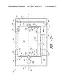
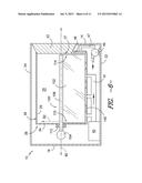
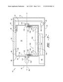
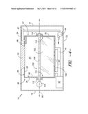
[0037] Referring to FIGS. 2 through 7, for example, various schematic side views of dryer assemblies 10 are illustrated. Dryer assembly 10 may, for example, include one or more baffle assemblies 100. A baffle assembly 100 according to the present disclosure may generally be rotatable within chamber 25. Such rotation may cause the baffle assembly 100 to contact articles contained within the chamber 25 and generally scoop or otherwise tumble the articles, thus facilitating drying of such articles by exposing various surface of the articles to the hot air within the chamber 25. A baffle assembly 100 may include, for example, a baffle 102 and a motor 104. Baffle 102 may generally extend within chamber 25, such as along longitudinal axis 80, and be rotatable within the chamber 25. Motor 104 may operate to rotate baffle 102. Further, as illustrated, a baffle assembly 100 may include an arm 106 which connects the baffle 102 to the motor 104. Arm 106 may, for example, include one or more linear members which extend within chamber 25 and support baffle 102. One end of arm 106 may be connected to motor 104, such that rotation of motor 104 rotates the arm 106, and thus the baffle 102 connected thereto.
[0038] In some embodiments, as illustrated for example in FIGS. 3, 4 and 7, baffle assembly 100 may be simply supported within chamber 25. For example, as shown in FIGS. 3 and 7, baffle assembly 100 may further include a secondary arm 108. Arm 106, which may also be referred to as a first arm 106, may extend between motor 104 and a first end 110 of baffle 102. The first arm 106 may further extend through drum 26, such as rear wall 34 thereof, to be coupled to motor 104, and bearing 112 may support the arm 106 and facilitate rotation thereof. Secondary arm 108 may extend between second end 114 of baffle 102 and the drum 26, and thus support the second end 114. The second arm 108 may further extend through drum 26, such as the front wall 30 thereof, and bearing 116 may support the arm 108 and facilitate rotation thereof.
[0039] In exemplary embodiments, baffle 102 may be rotatable about the longitudinal axis 80. For example, each arm 106, 108 may include a radial portion 120 which is coupled to bearing 112, 116, and may further include an axial portion 122 coupled to the respective radial portion 120. Accordingly, at least a portion (the radial portion 120) of each arm 106, 108 may extend radially within the chamber 25, such as adjacent to the rear wall 34 and front wall 30, respectively. Axial portions 122 of one or both arms 106, 108 may be generally parallel to longitudinal axis 80, and may further be coaxial with longitudinal axis 80, such that baffle 102 is rotatable about the longitudinal axis 80.
[0040] As shown in FIG. 4, arm 106 may extend between and through the rear wall 34 and front wall 30, and may be supported by bearings 112, 116. The arm 106 in these embodiments may extend axially within the chamber 25, such as generally parallel to or further coaxial with longitudinal axis 80. Baffle 102 may be connected to the arm 106 generally along at least a portion thereof between the walls 34, 30, and may for example be rotatable about the longitudinal axis 80.
[0041] It should be noted that in the embodiments disclosed in FIGS. 3, 4 and 7, entry 32 is defined in top cover 24 and cylinder 28, and front wall 30 is a generally solid wall, thus facilitating the simple support of the bearing assembly 100.
[0042] In other embodiments, as illustrated for example in FIGS. 2, 5 and 6, baffle assembly 100 may be cantilevered within chamber 25. For example, as shown in FIGS. 2 and 5, arm 106 may extend between motor 104 and a first end 110 of baffle 102. The first arm 106 may further extend through drum 26, such as rear wall 34 thereof, to be coupled to motor 104, and bearing 112 may support the arm 106 and facilitate rotation thereof. No secondary arm or other support of baffle 102 at end 114 may be provided.
[0043] In exemplary embodiments, baffle 102 may be rotatable about the longitudinal axis 80. For example, arm 106 may include a radial portion 120 which is coupled to bearing 112, and may further include an axial portion 122 coupled to the radial portion 120. Accordingly, at least a portion (the radial portion 120) of arm 106 may extend radially within the chamber 25, such as adjacent to the rear wall 34. Axial portion 122 may be generally parallel to longitudinal axis 80, and may further be coaxial with longitudinal axis 80, such that baffle 102 is rotatable about the longitudinal axis 80.
[0044] As shown in FIG. 6, arm 106 may extend between and through the rear wall 34, and may be supported by bearing 112. The arm 106 in these embodiments may extend axially within the chamber 25, such as generally parallel to or further coaxial with longitudinal axis 80. Baffle 102 may be connected to the arm 106 generally along at least a portion thereof between the walls 34, 30, and may for example be rotatable about the longitudinal axis 80.
[0045] It should be noted that in the embodiments disclosed in FIGS. 2, 5 and 6, entry 32 is defined in front wall 30. Alternatively, entry 32 may be defined in top cover 24 and cylinder 28.
[0046] Referring to FIG. 7, in some embodiments a baffle assembly 100 may further include one or more spring mechanisms 130. As illustrated, spring mechanisms 130 may generally bias the baffle 102 towards the inner surface 29 of the drum 26. The baffle 102 may thus, for example, contact the inner surface 29 due to such biasing. Spring mechanisms 130 may be disposed between baffle 102 and at least a portion of the arm(s) of the baffle assembly 100. For example, as illustrated, spring mechanisms 130 may be disposed between the axial portions 122 and radial portions 120 of arms 106, 108. Alternatively, spring mechanisms 130 may be disposed between radial portions 120 and the baffle 102, or between an axially extending arm 106 and the baffle 102. In exemplary embodiments, spring mechanism 130 may be or include a compression spring. Alternatively, spring mechanism 130 may be any suitable apparatus for biasing the baffle 102 towards the inner surface 29.
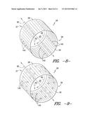
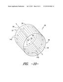
[0047] Referring now to FIGS. 8 through 10, further features of dryer assemblies 10 according to the present disclosure are illustrated. As illustrated, one or more sensors 140 may be provided in the drum 26 of a dryer assembly 10, such as disposed on the inner surface 29 thereof. Advantageously, the arrangement of the sensors 140 may increase the frequency of contact between the sensors 140 and articles during dryer assembly 10, such that sensor measurements are increased and/or more accurate. Such sensors 140 may be configured to measure various characteristics during operation of the dryer assembly 10, and may for example be in communication with the controller 56 to facilitate operation of the dryer assembly 10. Each sensor 140 may, for example, measure at least one of temperature, humidity or moisture content within the chamber 25. Such measurements may be made of the air within chamber 25 and/or the articles, such as the fabric thereof, within the chamber 25. Thus, a sensor 140 may be or include a thermometer and/or a humidity and/or moisture sensor. In exemplary embodiments, a sensor 140 may measure temperature, humidity and moisture content. Further, sensors 140 may additionally or alternatively measure other suitable characteristics of, for example, the chamber 25 or articles within the chamber 25 during operation of the dryer assembly 10.
[0048] As illustrated, sensors 140 may have any suitable arrangements on the inner surface 29. For example, in some embodiments, as illustrated in FIG. 8, sensors 140 may be disposed in one or more generally linear arrays which may, for example, extend parallel to the longitudinal axis 80. Alternatively, as illustrated in FIGS. 9 and 10, sensors 140 may be disposed in one or more generally circumferential array. For example, as illustrated in FIG. 9, sensors 140 may be arranged in one or more generally circular arrays along the circumferential axis 84. Alternatively, as illustrated in FIG. 10, sensors 140 may be arranged in one or more generally semi-circular arrays along the circumferential axis 84, each of which may span an approximate half-circle, an approximate three-quarters circle, or any other suitable portion of a circle. Still further, any suitable pattern or array of sensors 140 is within the scope and spirit of the present disclosure.
[0049] The use of sensors 140 disposed on inner surface 29 and in various patterns as discussed herein advantageously facilitates contact between the sensors and articles within chamber 25, thus advantageously increasing the sensing capabilities of the drying assembly 100 in general.
[0050] Referring now to FIGS. 11 through 15, further features of dryer assemblies 10 according to the present disclosure are illustrated. In particular, various embodiments of baffles 102 for use in baffle assembly 100 are illustrated. A baffle 102 may, for example, include a body 150 and a contact tip 152. The contact tip 152 may, for example, contact the inner surface 29 of the drum 26. As illustrated, the contact tip 152 may in exemplary embodiments be formed from, for example, a felt or a rubber. In general, a felt according to the present disclosure is a non-woven textile produced by, for example, matting, condensing, and/or pressing fibers together. Any suitable materials, including natural or synthetic fibers, may be utilized. A rubber according to the present disclosure may generally be a high-temperature rubber, and may be natural or synthetic. Further, contact tip 152 may alternatively be formed from any suitable high temperature material that is generally provides smooth contact with articles in the dryer assembly 10 and that is generally resistant to friction.
[0051] In some embodiments, as illustrated in FIG. 11, contact tip 152 may extend from body 150. Thus, contact tip 152 may be in contact with body 150 as well as inner surface 29. In other embodiments, as illustrated in FIG. 12, baffle 102 may further include one or more spring mechanisms 154 which bias the tip 152 towards the inner surface 29. In these embodiments, spring mechanisms 154 may be disposed between body 150 and tip 152.
[0052] In further embodiments, baffle 102 may include additional components to facilitate tumbling of articles within chamber 25. For example, and referring to FIGS. 13 and 14, baffle 102 may include one or more contact arms 160. Each contact arm 160 may, for example, extend from the body 150, such as generally from the body 150 towards the inner surface 29. In some embodiments as illustrated in FIG. 13, the contact tip 152 may extend from arm 160, or a contact tip 152 may extend from each arm 160. In other embodiments as illustrated in FIG. 14, contact tip 152 may extend from the body 150, while additional contact tips are provided on and extend from one or more arms 160.
[0053] Further, in some embodiments as illustrated in FIG. 13, baffle 102 may include a spring mechanism 162 connected to one or more contact arms 152. Spring mechanism 162 may bias the contact arm(s) 152 in a certain direction, such as towards each other as illustrated.
[0054] Referring to FIG. 15, baffle 102 may in some embodiments include one or more compliant members 164. Compliant members 164 may, for example, be formed from a suitable rubber or other compliant material. Compliant members 164 may, for example, be mounted to the body 150, and may be in contact with inner surface 29.
[0055] Baffle 102 and the various components thereof advantageously facilitate improved tumbling within fixed drum dryer appliances 10. For example, the contact tip 152, along with spring mechanisms 154, 162, contact arms 154, and complaint members 164, may provide improved contact of the baffle 102 with the inner surface 29, thus reducing or preventing the risk of articles becoming caught between the baffle 102 and the inner surface 29.
[0056] This written description uses examples to disclose the invention, including the best mode, and also to enable any person skilled in the art to practice the invention, including making and using any devices or systems and performing any incorporated methods. The patentable scope of the invention is defined by the claims, and may include other examples that occur to those skilled in the art. Such other examples are intended to be within the scope of the claims if they include structural elements that do not differ from the literal language of the claims, or if they include equivalent structural elements with insubstantial differences from the literal languages of the claims.
User Contributions:
Comment about this patent or add new information about this topic:
Images included with this patent application:
 |  |
 |  |
 |  |
 |  |
 |  |
 |  |
| New patent applications in this class: | |
| Date | Title |
|---|---|
| 2022-09-08 | Shrub rose plant named 'vlr003' |
| 2022-08-25 | Cherry tree named 'v84031' |
| 2022-08-25 | Miniature rose plant named 'poulty026' |
| 2022-08-25 | Information processing system and information processing method |
| 2022-08-25 | Data reassembly method and apparatus |
| New patent applications from these inventors: | |
| Date | Title |
|---|---|
| 2016-02-25 | Clothes dryer wireless moisture data transfer systems and energy-efficient methods of operation |
| 2015-12-24 | Clothes dryer with improved moisture sensing and wireless data transfer |
| 2014-12-04 | Integration of blower with washer motor shaft or drive shaft |
| 2014-10-02 | Air flow in a washing machine appliance |