Patent application title: THROUGH-THE-LENS (TTL) LOUPES WITH IMPROVED DECLINATION ANGLE
Inventors:
Byung J. Chang (Ann Arbor, MI, US)
Byung J. Chang (Ann Arbor, MI, US)
IPC8 Class: AG02C708FI
USPC Class:
359481
Class name: Optical: systems and elements binocular devices binocular loupe type
Publication date: 2015-05-28
Patent application number: 20150146290
Abstract:
Dental/medical/surgical loupes have an improved declination angle to
reduce neck and back strain. Eyeglass frames are provided with carrier
lenses having bottom edges. A hole is provided in each carrier lens, each
hole having an outer periphery that extends below the bottom edge of the
carrier lens, resulting in a pair of opposing pointed ends. A pair of
ocular devices are cemented in a respective one of the holes, such that a
portion of the ocular body also extends below the bottom edge of the
carrier lens. Each ocular is then cemented or otherwise permanently
affixed into position to achieve a desired declination angle. For added
stability, a pair of holes may be formed into the body of each ocular,
each pair of holes being physically aligned with the two opposing pointed
ends of the carrier lens associated with that ocular.Claims:
1. Loupes with an improved declination angle, comprising: eyeglass frames
with carrier lenses having bottom edges; a hole formed in each carrier
lens, each hole having an outer periphery that extends below the bottom
edge of the carrier lens, resulting in a pair of opposing pointed ends; a
pair of ocular devices, each having a body cemented in a respective one
of the holes, such that a portion of the ocular body also extends below
the bottom edge of the carrier lens; and wherein each ocular is cemented
in position to achieve a desired declination angle.
2. The loupes of claim 1, further including a pair of holes formed into the body of each ocular, each pair of holes being physically aligned with the two opposing pointed ends of the carrier lens associated with that ocular, such that the cement also enters into each hole to provide additional structural stability.
3. The loupes of claim 1, wherein: the ocular bodies are frusto-conical; and hole formed in each carrier lens is circular, semi-circular or oval shaped.
Description:
REFERENCE TO RELATED APPLICATIONS
[0001] This application claims priority from U.S. Provisional Patent Application Ser. No. 61/909,405, filed Nov. 27, 2013, and is also a continuation-in-part of U.S. Design patent application Ser. No. 29/480,902, filed Jan. 30, 2014. The entire content of both of which are incorporated herein by reference.
FIELD OF THE INVENTION
[0002] This application relates generally to telemicroscopic loupes of the type worn by surgical, medical and dental practitioners and, in particular, to so-called through-the-lens (TTL) loupes and, more particularly, to methods and apparatus for improving the declination angle of TTL loupes.
BACKGROUND OF THE INVENTION
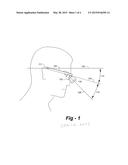
[0003] There are different types of loupes for surgical, medical and dental applications, including frame-mounted and flip-up styles and through-the-lens (TTL) loupes. Making reference to FIG. 1, the declination angle of loupes may be defined as the angle 114 between a reference line 104 connecting the top of the ears 117 (where the frame arm rests) to the corner of the eyes, and the optical axis 106 of the loupe oculars. The frame temple arm 120 may be used as the reference line if the temple arms are mounted at the same level with eyes (keeping in mind that the temple arms of some frames are higher than eye level).
[0004] While it is relatively easy to increase declination angle with "flip-up" loupes because the oculars do not need the eyeglass lenses for support, the positioning of existing TTL oculars is limited by the bottom edge of each lens 122. As such, a significant problem with TTL loupes is the relatively small declination angle due to the limitation of size of the carrier lens. This causes the user to bend their head downwardly from the horizontal 102 at a head angle of 112 (or greater), which may result in neck strain. Thus, any technique to increase the declination angle in TTL loupes would result in a more ergonomic design.
SUMMARY OF THE INVENTION
[0005] This invention improves upon the existing art by providing loupes having an improved declination angle. The invention involves eyeglass frames with carrier lenses having bottom edges. A hole is provided in each carrier lens, each hole having an outer periphery that extends below the bottom edge of the carrier lens, resulting in a pair of opposing pointed ends. A pair of ocular devices are cemented in a respective one of the holes, such that a portion of the ocular body also extends below the bottom edge of the carrier lens. Each ocular is then cemented or otherwise permanently affixed into position to achieve a desired declination angle. For added stability, a pair of holes may be formed into the body of each ocular, each pair of holes being physically aligned with the two opposing pointed ends of the carrier lens associated with that ocular, such that the cement also enters into each hole, thereby stabilizing the pointed ends. The ocular bodies may be frusto-conical, in which case the hole formed in each carrier lens may be circular, semi-circular or oval shaped.
BRIEF DESCRIPTION OF THE DRAWINGS
[0006] FIG. 1 is a drawing that shows geometries associated with eye-worn oculars;
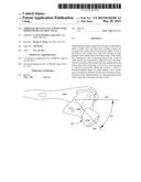
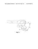
[0007] FIG. 2 illustrates the preferred embodiment of the invention, wherein the declination angle is improved;
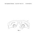
[0008] FIG. 3 is a view from a user's viewpoint showing attachment points; and
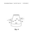
[0009] FIG. 4 is drawing that depicts how holes may be drilled into the ocular bodies to enhance assembled stability.
DETAILED DESCRIPTION OF THE INVENTION
[0010] In order to overcome the limitations of the prior art in terms of limited declination angle, this invention is directed to a new mounting method that significantly increases the declination angle and promotes a more healthy posture. In broad and general terms, instead of forming a complete bore through each eyeglass lens surrounded by lens material, the lower portion of each bore intersects with the bottom edge of each lens, such that a portion of the barrel of each ocular actually extends below the bottom edge of each lens, thereby increasing the declination angle.
[0011] FIG. 2 is a side view that illustrates a typical configuration. Eyeglass frames 220 include lenses 230 through which ocular(s) 210 are mounted. The declination angle 214 is shown between reference line 204 and the optical axis 206 of the ocular 210. Again, the temple arm of the frame 220 may be used as the reference line if the temple arms are mounted at the same level with eyes. Although the frames depicted are of a specific "designer" variety, virtually any style is applicable. Although the invention is preferably used with lenses that have no bottom rim, the system and method may actually be used with lenses that have bottom rims so long as they can be modified as described herein.
[0012] Broadly according to the invention, a bore is formed through each lens in such a way that the outline of each bore intersects with the bottom edge of each lens, thereby forming an open semi-circle in the bottom of each carrier lens with two points 330, 332. With this configuration, loupes may be positioned further downwardly on each lens, thereby increasing the declination angle, DA. If the outer surface of the ocular body is frusto-conical, the bore through each lens is generally circular or slightly oval. The invention may be deployed by modifying existing lenses, particularly if plastic, or by providing lenses with the desired shape in the first place.
[0013] FIG. 3 shows the structure from a wearer's perspective. The eyeglass frames are shown at 220. A hole is drilled in each carrier lens 230 such that a portion of the periphery of the hole 232 extends beyond the bottom edge of the lens creating a pair of opposing pointed ends 330, 332 (FIG. 2). The ocular 210 is then aligned on a fixture for a desired DA and cemented into position.
[0014] While the oculars may simply be cemented in each semi-circular cut-out without further modification, in the preferred embodiment, small holes are drilled in the outer surfaces of the oculars to assist with correct positioning and stability. As shown in FIG. 4, these holes 334, 336 are drilled into the body of each ocular 232 so as to align with the pointed ends 330, 332 of the carrier lens 230. When the cement is applied, a portion of the cement flows into the holes, maintain the structural integrity of the assembly.
User Contributions:
Comment about this patent or add new information about this topic:
| People who visited this patent also read: | |
| Patent application number | Title |
|---|---|
| 20200412542 | BLOCKCHAIN-IMPLEMENTED METHODS AND SYSTEMS FOR AUTHORISATION BASED ON BILINEAR MAP ACCUMULATORS |
| 20200412541 | AUTHENTICATION LEDGER INTERACTIONS FOR DECENTRALIZED BIOMETRIC AUTHENTICATION |
| 20200412540 | DISTRIBUTION OF SECURITY CREDENTIALS |
| 20200412539 | SYSTEMS AND METHODS FOR USER-BASED AUTHENTICATION |
| 20200412538 | SERVERLESS CONNECTED APP DESIGN |
Images included with this patent application:
 |  |
 |  |
 |
| Similar patent applications: | |
| Date | Title |
|---|---|
| 2015-05-14 | Lens stopper mechanism |
| 2010-04-15 | Double-layer grating |
| 2011-02-24 | Rens moving module |
| 2014-11-06 | Closed cell materials |
| 2015-05-14 | Lens drive device |
| New patent applications in this class: | |
| Date | Title |
|---|---|
| 2016-07-07 | Eyepiece system and image observation apparatus |
| 2015-11-19 | Ttl adjustable binocular loupes device |
| 2014-01-30 | Binocular goggles |
| 2013-04-18 | Mechanically stabilized optical mounting assembly |
| 2012-09-06 | Adjustable optical assembly and method |
| New patent applications from these inventors: | |
| Date | Title |
|---|---|
| 2022-08-25 | Head-mountable illuminators with user-selectable color temperature |
| 2021-02-04 | Removable, adjustable wire arms for nose pads |
| 2014-10-02 | High-efficiency led illuminator with improved beam quality and ventilated housing |
| 2014-09-04 | High-efficiency led illuminator with improved beam quality |
| Top Inventors for class "Optical: systems and elements" | |
| Rank | Inventor's name |
|---|---|
| 1 | Tsung Han Tsai |
| 2 | Hsin Hsuan Huang |
| 3 | Michio Cho |
| 4 | Niall R. Lynam |
| 5 | Tsung-Han Tsai |