Patent application title: Superneat toilet seat
Inventors:
Carl E. Humphrey, Jr. (Brandywine, MD, US)
IPC8 Class: AA47K1330FI
USPC Class:
4233
Class name: Baths, closets, sinks, and spittoons disinfection seat and cover treating
Publication date: 2015-04-02
Patent application number: 20150089728
Abstract:
A toilet seat attachment assembly that when fully deployed onto a
conventional toilet, to form a self-cleaning adjustable height urinal.
The seat assembly is comprised of separate upper and lower seat sections.
The upper seat section is adapted to be lifted upward and rotated forward
a maximum 90 degrees relative to a rear of the seat assembly, adjacent a
toilet tank of a conventional toilet. Once fully deployed, the seat
assembly reveals a series of self-cleansing outer and inner flexible
shields connected together in an accordion like manner, which are
attached at ends thereof to both the upper and lower sections of the seat
assembly. The upper seat section is comprised of an encapsulating shell
that is designed to encase the outer shield of the collapsible funnel, so
as to support the weight of a seated user when the seat assembly is
lowered and used as a conventional toilet seat.Claims:
1. A toilet seat attachment assembly comprised of separate upper and
lower seat sections, the upper seat section adapted to be lifted upward
and rotated forward a maximum 90 degrees relative to a rear of the seat
assembly, adjacent a toilet tank of a toilet, the seat assembly, when
fully deployed in a fixed upright use position, reveals a series of outer
and inner flexible shields connected together, so as to be extendable
between a collapsed and a fixed upright extended hollow tubular funnel,
opposed ends of which are attached, respectively, to both the upper and
lower sections of the seat assembly; the upper seat section comprised of
a rigid encapsulating shell that is designed to encase the outer shields
of the funnel as the seat assembly is lowered to a collapsed position and
used as a toilet seat of the toilet, so as to support the weight of a
user seated thereon; and when fully deployed onto the toilet seat in the
fixed use position, the seat assembly further comprising a means for
self-cleaning an interior surface of the funnel as the funnel is lowered
or raised from the collapsed position to the fully deployed fixed upright
use position, so as to form an adjustable height urinal.
2. The seat assembly of claim 1, wherein the means for self-cleaning comprises a water supply tube one end of which is attached to a water intake hose, the supply tube running diagonally along a perimeter of the inner flexible shield, the supply tube having holes therein from which pressurized water is adapted to be ejected, water that has been drawn through the water intake hose, which is adapted to be connected to an existing water line that is used to feed pressurized water to the toilet, to which the water intake hose is adapted to be securely attached; wherein when the toilet is flushed during normal use, the water intake hose is connected to a water intake valve located within a housing of the lower seat section, opening and closing of the valve allowing for feeding of the pressurized water into the water supply tube along the inner shield and through the holes therein onto an inner surface of the inner shield, thus rinsing any liquid from urination of a user from the inner surface when the seat assembly is in the fully deployed fixed use position.
3. The seat assembly of claim 2, further comprising a water release valve, housed within the lower seat section, through which the pressurized water bypassed from the existing water line is adapted to be fed, the pressurized flow of water through the water release valve adapted to be shut off as a user lowers the upper seat section until it is flush with and encases the lower seat section, wherein there is a water overflow stop that is adapted to be positioned inside a toilet bowl of the toilet, and if a user does not lower the upper section onto the lower seat section after use, and after a flush of the toilet and wherein once the water rising within a toilet bowl of the toilet engages the water overflow stop, the water release valve to which the water overflow stop is attached, is repositioned within the housing of the lower seat assembly so as to automatically shut off the flow of water within the water supply tube.
4. The seat assembly of claim 2, wherein the means for self-cleaning comprises a water release system having a water intake hose that is adapted to feed pressurized water into the water release system from the existing water line to which an end of the water intake hoes is attached, so that water from the existing water line is channeled into the water intake hose where it enters into a release valve, wherein as the upper seat section is lifted to the fixed use position, wherein the upper seat section has housed therein a water release arm that has a water release tab thereon engages the release valve as the upper seat section is raised and forces the release valve into an open position, and the pressurized water then enters the supply tube, thus allowing for free flow movement of water throughout remaining portions of the supply tube and ejected through the holes.
5. The seat assembly of claim 4, wherein the water release arm sits within a groove housed within the upper seat section and the water release arm moves within the groove as the upper seat section is lowered or raised from the collapsed position to the fully deployed fixed upright use position, wherein as the water release arm moves within the groove and in unison with upper seat section, the water release tab engages the water release valve; and as the upper seat section is raised to a 90 degree angle relative to the toilet tank, the water release tab subsequently engages the water release valve to open the flow of pressurized water with the water supply tube; and if the user does not lower the upper seat section after use, the water level inside a toilet bowl of the toilet will rise after a flush of the toilet and engage a water overflow stop, to which the water release valve is attached, the water release valve is then repositioned within the housing of the lower seat assembly so as to automatically shut off the flow of water within the water supply tube, thus terminating the flow of pressurized water within the water supply tube and through the holes.
6. A toilet seat attachment assembly comprised of separate upper and lower seat sections, the upper seat section adapted to be lifted upward and rotated forward a maximum 90 degrees relative to a rear of the seat assembly, adjacent a toilet tank of a toilet, the seat assembly, when fully deployed in a fixed upright use position, reveals a series of outer and inner flexible shields connected together, so as to be extendable between a collapsed and a fixed upright extended hollow tubular funnel, opposed ends of which are attached, respectively, to both the upper and lower sections of the seat assembly; the upper seat section comprised of a rigid encapsulating shell that is designed to encase the outer shields of the funnel as the seat assembly is lowered to a collapsed position and used as a toilet seat of the toilet, so as to support the weight of a user seated thereon; and when fully deployed onto the toilet seat in the fixed use position, the seat assembly further comprising a water supply tube one end of which is attached to a water intake hose, the supply tube running diagonally along a perimeter of the inner flexible shield, the supply tube having holes therein from which pressurized water is adapted to be ejected, water that has been drawn through the water intake hose, which is adapted to be connected to an existing water line that is used to feed pressurized water to the toilet, to which the water intake hose is adapted to be securely attached; wherein when the toilet is flushed during normal use, the water intake hose is connected to a water intake valve located within a housing of the lower seat section, opening and closing of the valve allowing for feeding of the pressurized water into the water supply tube along the inner shield and through the holes therein onto an inner surface of the inner shield, thus rinsing any liquid from urination of a user from the inner surface when the seat assembly is in the fully deployed fixed use position.
7. The seat assembly of claim 6, further comprising a water release valve, housed within the lower seat section, through which the pressurized water bypassed from the existing water line is adapted to be fed, the pressurized flow of water through the water release valve adapted to be shut off as a user lowers the upper seat section until it is flush with and encases the lower seat section, wherein there is a water overflow stop that is adapted to be positioned inside a toilet bowl of the toilet, and if a user does not lower the upper section onto the lower seat section after use, and after a flush of the toilet and wherein once the water rising within a toilet bowl of the toilet engages the water overflow stop, the water release valve to which the water overflow stop is attached, is repositioned within the housing of the lower seat assembly so as to automatically shut off the flow of water within the water supply tube.
8. The seat assembly of claim 6, further comprising a water release system having a water intake hose that is adapted to feed pressurized water into the water release system from the existing water line to which an end of the water intake hoes is attached, so that water from the existing water line is channeled into the water intake hose where it enters into a release valve, wherein as the upper seat section is lifted to the fixed use position, wherein the upper seat section has housed therein a water release arm that has a water release tab thereon engages the release valve as the upper seat section is raised and forces the release valve into an open position, and the pressurized water then enters the supply tube, thus allowing for free flow movement of water throughout remaining portions of the supply tube and ejected through the holes.
9. The seat assembly of claim 8, wherein the water release arm sits within a groove housed within the upper seat section and the water release arm moves within the groove as the upper seat section is lowered or raised from the collapsed position to the fully deployed fixed upright use position, wherein as the water release arm moves within the groove and in unison with upper seat section, the water release tab engages the water release valve; and as the upper seat section is raised to a 90 degree angle relative to the toilet tank, the water release tab subsequently engages the water release valve to open the flow of pressurized water with the water supply tube; and if the user does not lower the upper seat section after use, the water level inside a toilet bowl of the toilet will rise after a flush of the toilet and engage a water overflow stop, to which the water release valve is attached, the water release valve is then repositioned within the housing of the lower seat assembly so as to automatically shut off the flow of water within the water supply tube, thus terminating the flow of pressurized water within the water supply tube and through the holes.
10. The seat assembly of claim 6, wherein the upper and lower seat sections are fabricated from rigid polymeric materials.
11. The seat assembly of claim 10, wherein the series of outer and inner flexible shields are fabricated from a flexible non-absorbent material and includes a removable deodorizing material to coat the inner shield.
12. The seat assembly of claim 8, wherein the upper and lower seat sections are fabricated from rigid polymeric materials.
13. The seat assembly of claim 12, wherein the series of outer and inner flexible shields are fabricated from a flexible non-absorbent material and includes a removable deodorizing material to coat the inner shield.
14. The seat assembly of claim 1, wherein the upper and lower seat sections are fabricated from rigid polymeric materials.
15. The seat assembly of claim 14, wherein the series of outer and inner flexible shields are fabricated from a flexible non-absorbent material and includes a removable deodorizing material to coat the inner shield.
16. The seat assembly of claim 5, wherein the upper and lower seat sections are fabricated from rigid polymeric materials.
17. The seat assembly of claim 16, wherein the series of outer and inner flexible shields are fabricated from a flexible non-absorbent material and includes a removable deodorizing material to coat the inner shield.
Description:
FIELD OF THE INVENTION
[0001] This invention generally relates to a urinating aid for a conventional toilet. More specifically, the invention pertains to an apparatus which can be removably attached to a conventional toilet and provides an expandable/collapsible flexible urinal that is self cleaning after each use.
BACKGROUND OF THE INVENTION
[0002] 1. The Field of the Invention
[0003] Devices that assist with urination, i.e., urinal type devices that can be attached to a common toilet bowl seat, have been helpful aids to assist those individuals that need assistance in urinating. These devices are commonly referred to as toilet shields, toilet guards, splash shields, urinal aids, or toilet pan. In practice however, these toilet seat attachable devices simply allow for a portable urinal device that can aid a user, such as young children, elderly, or disabled individuals during the act of urination, while in a standing position.
[0004] It is very common for devices of this type to have tubular shaped components or shielding attachments that can attach to and extend upwardly from an existing toilet seat assembly. In some instances, a lower portion these devices can be press fitted into a toilet bowl or toilet seat, while others can be clamped on by fastening means. There is typically a linkage assembly or a flexible means that allows for the device to placed in an adjustable extended or use position. Conversely, when not in use, the device can either be lowered into a collapsed position or removed, so as to be stored until used again. The height can be varied to accommodate users of various heights, disabilities, and different ages.
[0005] There have been attempts to ensure that these type urinal aid devices have surfaces that are readily cleanable or even repel water, as repetitive use thereof would clearly require to ensure sanitary conditions. Other devices may contain flushing systems, however, there is still a need for a device that can accomplish all of the aforementioned elements of urinal aid devices.
[0006] 2. Description of Related Art
[0007] An examination of the prior art of record discloses various types of urinal aid devices. US Patent Application Publication No. US 2008/0244817 A1 to Sailer et al (herein "Saller-817"), discloses a device which enables a toilet seat to be used either as a urinal or as a toilet for sitting upon. The device is comprised of a mounting device 7 that allows for attachment to a toilet seat 6, and toilet lid 10, 11. The device has a funnel shaped wall 13 that is made from a flexible textile or film material that can be dirt and water repellant. The wall 13 can be attached to a foldable linkage assembly 9, 12, 16, 25, 26, 27, 29 that assist in selectively adjusting the height of the wall 13 relative to the toilet seat 6. There are actuating levers 15, 16 that initiate opening and closing the device. However, there is no self contained flushing system that aids in keeping the device sanitary.
[0008] U.S. Pat. No. 4,348,776 to Sarjeant (herein "Sarjeant-776"), discloses a collapsible splash shield 20, 40 for a toilet 10. The shield 20 can be extended between raised and collapsed storage positions. The shield 20, 40 has segments 21-23 and 52, 53, respectively, that can telescope within one another to create a plastic and extendable shield assembly. Mounting members 22, 41 along with flanges 24, 44, facilitate attachment of shield 20, 40 to toilet bowl 11. This arrangement allows for a urinal aid device that is adjustable in height, collapsible for storage, and does not interfere with normal use of the toilet. The shield however, fails to disclose a self contained flushing system that can assist in keeping the device sanitary.
[0009] U.S. Pat. No. 5,564,135 to Jones et al (herein "Jones-135"), discloses a toilet splash guard 20 comprised of a linkage assembly 56, 60, 66, flexible funnel shaped pleated sections 72, 74, 78 that form shield 44. Guard 20 can be attached to toilet seat 32 by means of hinges 68, 68', and to toilet bowl 30 by means of base plate 34. When link arms 56 and 60 are linearly aligned, the shield 20 is the open use position. When arm 56 is parallel to base plate 34, the shield 20 is in a non use position. Again, the prior art of record fails to disclose a self flushing or cleansing means to keep the shield in a sanitary condition.
[0010] U.S. Pat. No. 5,077,840 to Masters et al (herein "Masters et al-840"), discloses a device 101 for channeling urine to a toilet bowl 5. The device is attached to the bowl 5 by means of abutments 3 and clip portions 19 formed therein to provide a snap fit connection to bowl 5. The device is not adjustable in nature, nor does it provide a self rinsing or cleaning system to maintain sanitary conditions.
[0011] None of the aforementioned prior art of record addresses the utility of a self cleaning system for a urinal aid, nor a urinal aid that is extendable into a rotatable locked position that is height adjustable for users of various heights, ages, and disabilities. Herein lays the novel aspects of the instant invention that will be discussed in detail.
SUMMARY OF THE INVENTION
[0012] The present invention provides a means for cleanly use of a toilet while standing during urination. The invention is drawn to a toilet seat attachment assembly that when fully deployed onto a conventional toilet, forms a self cleaning, adjustable height urinal. The seat assembly is comprised of separate upper and lower seat sections. The upper seat section is adapted to be lifted upward and rotated forward a maximum 90 degrees relative to a rear of the seat assembly, adjacent a toilet tank of a conventional toilet. Once fully deployed, the seat assembly reveals a series of outer and inner flexible shields connected together in an accordion like manner, which are attached at ends thereof to both the upper and lower sections of the seat assembly. This arrangement creates a collapsible funnel extending from the upper section to the lower section. The upper seat section is comprised of an encapsulating shell that is designed to encase the outer shield of the collapsible funnel, so as to support the weight of a seated user when the seat assembly is lowered and used as a conventional toilet seat. The inner shield of the collapsible funnel is designed to direct liquid flow into a conventional toilet bowl. The inner shield also contains a self cleaning system housed therein. The self cleaning system consists of a water supply tube that runs diagonally along the perimeter of the inner shield. The water supply tube of the self cleaning system has holes therein from which clean water is ejected or sprayed, water that has been drawn from the existing water line, to which the water intake hose is attached. The water for the self cleaning system is drawn from a house water line that is used to feed water to the toilet itself. As the toilet is flushed during normal use, a water intake hose connected to a water intake valve, feeds pressurized water into the water supply tube along the inner shield and through the holes therein onto an inner surface of the inner shield, thus rinsing any remaining liquid, i.e., urine from the inner surface. There is a water release valve through which the pressurized water bypassed from the house water line is fed. To end flow of water through the water release valve, a user simply lowers the upper section until it is flush with the lower section. Were a user to not lower the upper section after use, there is a water overflow stop that is positioned inside the toilet bowl, wherein once the water rising within the toilet bowl engages the water overflow stop, the water release valve to which the water overflow stop is attached, automatically shuts off the flow of water within the water supply tube. This assembly and interaction of components, provides for a self cleaning water system for the urinal aid device envisioned herein.
[0013] To initially use the device, the upper section of the seat assembly is raised and fixedly secured at a desired height, thereby expanding the collapsible funnel into a fixed use position. As a user then urinates into the funnel, the funnel essentially limits the extent of urine flow from the user's body to the toilet, while guiding the urine into the toilet bowl. The seat assembly serves to assist a person that may have trouble directing their urine flow downward into the toilet bowl. This will help prevent the urine that is expelled out of the user's body from reaching surfaces, such as the seat area, base of the toilet, and surrounding floor areas, where the presence of urine creates an unsanitary condition.
[0014] There are several ways that the seat assembly may be opened or closed. The seat assembly may be opened by a handle attached to or recessed within the upper section of the seat's shell that may contain a lip that extends under a ridge on the bottom half of the seat. This holds the seat closed and provides a means to open the shell. Another opening mechanism to be provided will be a foot actuated opening mechanism consisting of a series of levers that extend down from the side of the seat assembly to the floor. The next to last level nearest the bottom will be adjustable to account for multiple height toilets. Yet another option to be provided is a hand lever that rests across the top of the tank and down the front face of the tank. The lever slides down and opens the seat. The two latter options are to provide a way to open the seat without the need to touch it providing for a more sanitary experience.
[0015] By reducing the soiling of surrounding surfaces, they are kept clean, while providing an environmentally friendly way of keeping the surrounding surfaces clean by reducing the frequency of chemicals used to clean the surrounding surfaces, which can be harmful to the atmosphere, water systems in the form of runoff or sewer discharge, and to a user by direct contact.
[0016] The present invention can be fabricated from a combination of polymeric materials, paper, wax coating, and can also include urinal cake material, i.e., a removable deodorizing material to coat the inner shield.
TABLE-US-00001 LIST OF REFERENCE CHARACTERS 1. Upper Seat 2. Lower Seat 3. Seat Handle 4. Seat Lid 5. Water intake hose 6. Water channel screw 7. Water intake valve 8. Outer funnel 9. Inner funnel 10. Support arm 11. Water release valve 12. Water release arm 13. Water release tab 14. Seat support bracket 15. Water supply tube 16. Water spray nozzle 17. Upward lift 18. Rotate 90 degrees 19. Upper seat pivot points of support arm 20. Toilet bowl 21. Toilet Bowl 22. Toilet Tank 23. Tank lever 24. House water line 25. Water level 26. Water release system 27. Water release valve spring 28. Water release arm dovetail groove
BRIEF DESCRIPTION OF THE DRAWINGS
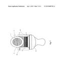
[0017] FIG. 1 is a side view of the SuperNeat Seat in a closed non use position.
[0018] FIG. 2 is a side view of the SuperNeat Seat with a cut away showing the interior elements of the upper seat and lower seat.
[0019] FIG. 3 is a side view of the SuperNeat Seat in an upright open use condition.
[0020] FIG. 4 is a side view of the SuperNeat Seat in an upright extended lifted open use condition.
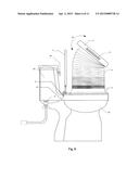
[0021] FIG. 5 is a side view of the SuperNeat Seat in an upright extended lifted open use condition with interior elements shown through the transparent outer funnel.
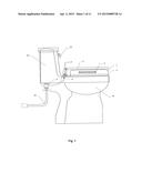
[0022] FIG. 6 is a side view of the SuperNeat Seat in a partially lifted and rotated condition.
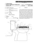
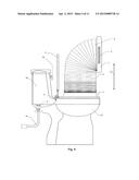
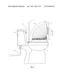
[0023] FIG. 7 is a front view of the SuperNeat Seat in an upright extended lifted open use condition.
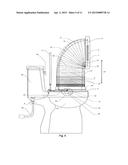
[0024] FIG. 8 is a front view of the SuperNeat Seat in an upright extended lifted open use condition with interior elements shown through the transparent outer funnel.
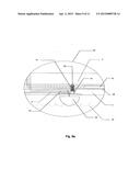
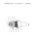
[0025] FIG. 9a is an exploded view of the water release system in a closed position.
[0026] FIG. 9b is an exploded view of the water release system in an open position.
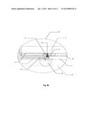
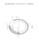
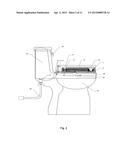
[0027] FIG. 10 is a sectional view of the lower seat assembly, as shown in FIG. 7.
DETAILED DESCRIPTION OF THE PREFERRED EMBODIMENT
[0028] FIG. 1 shows a side view of a conventional toilet tank 22, toilet seat lid 4, and toilet bowl 21 having a tank lever 23, a house water line 24 to which a water intake valve 7 is connected, a water intake hose 5 that is attached to water intake valve 7, a water channel screw 6 that connects a continuing portion of water intake hose 5 to lower seat 2. Lower seat 2 is the primary component of a base assembly (unnumbered) that is secured to an outer portion of toilet bowl 21. This base assembly may be attached to toilet bowl 21 by screws or other suitable fastening means (unnumbered). Lower seat 2 houses remaining components of a self cleaning system to be discussed later, and as best seen in FIGS. 2, 5, 9a, and 9b. There are seat handles 3 that are attached to or recessed within either side of and allow for vertical movement of upper seat 1. Upper seat 1 is preferably an oval shell (though any shape is contemplated) that encases the lower seat 2 and its components therein. Upper seat 1 also provides support for a user in a seated position, while protecting the other components.
[0029] FIG. 2 shows a cross section side view of upper seat 1 encased therein with outer funnel 8 and inner funnel 9, support arm 10 in collapsed position, water overflow stop 20, and water release valve 11. The functioning of water release valve 11 and the overflow stop 20 will be discussed later.
[0030] FIG. 3 shows the urinal aid herein in an open un-raised position, wherein the upper seat 1 has been rotated 90 degrees 18 relative to lower seat 2. Lid 4 has been rotated 90 degrees to an open use position as well. Note that in this position, lid 4 and upper seat 1 are essentially parallel to one another. Upper seat 1 may now be lifted vertically 17 by means of handles 3 to a raised use position, as best seen in FIG. 4.
[0031] FIG. 4 shows the urinal aid in a raised use position. Though not seen in this figure, the urinal aid may now be vertically adjusted in height to accommodate users of various heights.
[0032] FIG. 5 shows the interior components of the urinal aid in shadow, when the urinal aid is in a raised use position. Within inner funnel 9 and outer funnel 8, there lies water supply tubes 15, these tubes are preferably equally spaced along the interior of inner funnel 9. The water supply tubes 15 have therein a series of water spray nozzles/holes 16. The water supply tubes 15 extend from the lower seat upward to the upper seat 1. The water supply tubes 15 are distributed to maximize the surface area to be cleaned within the inner funnel 9. In shadow, a support arm 10 can be seen in a vertical support position. Support arm 10 is a locking telescopic arm that allows for the upper seat to be connected to the lower seat 2 in a fixed position when in use. The upper end of support arm 10 has a pivot arrangement 19 that allows for rotation of upper seat 1 relative to the support arm 10, and thus relative to lower seat 2. A water release valve system 26, comprised of water overflow stop 20, water release valve 11, shown in the circle on lower seat 2, will be discussed further in FIGS. 9a and 9b. Toilet bowl water level 25, shows the level of the water in the bowl when it engages stop 20.
[0033] FIG. 6 shows the urinal aid as it is partially lifted and rotated back to a non use position. Note that the outer funnel 8 is collapsing back into an accordion like position as it is being closed. As upper seat 1 is rotated 18, a user may adjustably set the position of upper seat 1 to adjust the angle at which a user may be most comfortable in a standing position.
[0034] FIG. 7 shows the urinal aid from a front view, while in the use raised position of FIG. 5. Note that in this position, the upper seat 1 provides a receptacle and guide-way for receiving urine therein. FIG. 8 similarly shows the interior elements as described in FIG. 5 above, while the urinal aid is in the raised use position.
[0035] FIGS. 9a and 9b are an exploded view of the water release system 26 in closed and open positions, respectively. Water release system 26 is comprised of water intake hose 5 that feeds pressurized water into the water release system 26 from house water line 24. Water from line 24 is channeled into hose 5 where it enters into release valve 11. As upper seat 1 is lifted, arm 12 engages valve 11 and forces the valve 11 into an open position, and then water enters tube 15, thus allowing for free flow movement of water throughout the remaining portions of tube 15 and eventually through nozzles 16. Were a user to not lower the upper seat 1 after use, the water level inside the toilet bowl would rise and engage water overflow stop 20, thus terminating the flow of pressurized water within water supply tube 15 and through nozzles 16. Water release arm 12 has a water release tab 13 that engages valve 11 and sits within water release arm groove 28, which is dovetailed in shape. Water release arm 12 moves in unison with upper seat 1, and as upper seat 1 reaches a 90 degree angle, water release tab 13 subsequently engages water release valve 11 to open the flow of pressurized water with water supply tube 15.
[0036] FIG. 10 shows a cross section of the urinal aid from FIG. 7. FIG. 10 shows arm 12 within groove 28, and tab 13 in the closed position.
[0037] A more detailed description of the urinal aid will now be described. In use, the upper seat 1 of the seat assembly is raised and secured to a desired height, thereby expanding the collapsible funnels 8, 9, into a use position. As a user then urinates into the funnels 8, 9, the funnels 8, 9, essentially limits the extent of urine flow from the user's body to the toilet, while guiding the urine into the toilet bowl. Upper seat 1 is adapted to be lifted upward and rotated forward a maximum 90 degrees relative toward tank 22. Once fully deployed, the urinal aid reveals a series of outer 8 and inner 9 flexible shields connected together in an accordion like manner to form funnels, which are attached at ends thereof to both the upper seat 1 and lower seat 2 of the urinal aid. This arrangement creates a collapsible funnel extending from upper seat 1 to the lower seat 2. The upper seat 1 is comprised of an encapsulating shell that is designed to encase the outer funnel 8 of the collapsible funnel. The inner funnel 9 of the collapsible funnel is designed to direct liquid (urine and water) flow into a conventional toilet bowl. The inner funnel 9 also contains a self cleaning system housed therein. The self cleaning system consists of water supply tube 15 that runs diagonally along the perimeter of the inner funnel 9. The water supply tube 15 of the self cleaning system has holes therein from which clean water is ejected or sprayed through nozzles 16, water that has been drawn from the existing house water line 24, to which the water intake hose 5 is attached. The water for the self cleaning system is drawn from house water line 24 that is used to feed water to the toilet itself. To end flow of water through the water release valve 11, a user simply lowers the upper seat 1 until it is flush with the lower seat 2. Were a user to not lower the upper seat 1 after use, the water overflow stop 20 that is positioned inside the toilet bowl would automatically shut off the flow of water within the water supply tube 15. This seat assembly and interaction of components, provides for a self cleaning water system for the urinal aid device envisioned herein.
[0038] The above embodiments of the instant invention have been presented so as to not limit the invention to only those embodiments. It is contemplated that obvious variations, modifications, and improvements are within the skill of one familiar to relevant arts.
User Contributions:
Comment about this patent or add new information about this topic:
Images included with this patent application:
 |  |
 |  |
 |  |
 |  |
 |  |
 |  |
| Similar patent applications: | |
| Date | Title |
|---|---|
| 2015-03-26 | System and method for converting a foldable chair into a toilet seat |
| 2015-02-12 | Apparatus, system and method for transporting a potty seat |
| 2013-03-28 | Warm toilet seat |
| 2014-07-24 | Bumperless toilet lid |
| New patent applications in this class: | |
| Date | Title |
|---|---|
| 2018-01-25 | Ultraviolet-based bathroom surface sanitization |
| 2016-05-12 | Ultraviolet-based bathroom surface sanitization |
| 2014-05-22 | Auto cleaning toilet seat and method of use |
| 2011-08-11 | Sanitary toilet seat |
| 2011-06-09 | Consumable product dispensing system and method |
| Top Inventors for class "Baths, closets, sinks, and spittoons" | |
| Rank | Inventor's name |
|---|---|
| 1 | William T. Ball |
| 2 | Joseph R. Cook |
| 3 | David Grover |
| 4 | Kun Yuan Tong |
| 5 | Victor Hoernig |