Patent application title: TEMPERATURE CONTROL DEVICE
Inventors:
Thomas Himmer (Reichenbach, DE)
Thomas Himmer (Reichenbach, DE)
IPC8 Class: AF25B2104FI
USPC Class:
62 33
Class name: Using electrical or magnetic effect thermoelectric; e.g., peltier effect heat pump, selective heating and cooling
Publication date: 2014-12-25
Patent application number: 20140373557
Abstract:
A temperature control device for temperature control of a component is
provided, whereby the component is in an electrical and/or an electronic
component, having a tube and a housing element, whereby a first fluid can
flow through the tube and a second fluid can flow around the temperature
control device. The housing element is formed by a cup-like cover, which
is connected to the tube and forms a receiving area for the component in
which the component is taken up.Claims:
1. A temperature control device for the temperature control of a
component, the device comprising: a tube; and a housing element, wherein
a first fluid flows through the tube and a second fluid flow around the
temperature control device, wherein the housing element is formed by a
cup-like cover that is connected to the tube and forms a receiving area
for the component in which the component is taken up.
2. The temperature control device according to claim 1, wherein the component is formed by a thermoelectric module, wherein the thermoelectric module has a module housing having at least two opposite first walls, wherein a plurality of thermoelectric elements are arranged between the first walls of the module housing, wherein the thermoelectric elements have opposite surfaces that are in thermal contact with one of the first walls of the module housing of the thermoelectric module, and wherein the thermoelectric elements are connected at least partially electrically to one another via conductive bridges.
3. The temperature control device according to claim 1, wherein the housing element has a first recess, the first recess being arranged on a surface of the temperature control device, said surface over which the second fluid flows.
4. The temperature control device according to claim 1, wherein the tube has a second recess, the second recess being arranged on a surface of the tube, said surface over which the first fluid flows.
5. The temperature control device according to claim 1, wherein the component is connected fluid-tight with the housing element at an edge region of a first recess and/or the housing element is connected fluid-tight to the tube.
6. The temperature control device according to claim 1, wherein the component has surface-increasing elements, the surface-increasing elements being arranged on a surface over which the first fluid flows or are arranged on a surface over which the second fluid flows.
7. The temperature control device according to claim 1, wherein at least one thermal decoupling element, which restricts the fluid flow of the first fluid to a section of the tube, is provided in the tube.
8. The temperature control device according to claim 1, wherein the housing element or the tube have an electrically insulating layer on at least one surface facing the component.
9. The temperature control device according to claim 2, wherein the module housing has second walls, which close the module housing fluid-tight with both first walls.
10. The temperature control device according to claim 9, wherein at least one of the second walls is formed by a ceramic wall element or a metallic wall element.
11. The temperature control device according to claim 9, wherein the second walls are connected fluid-tight to the first walls and/or are connected fluid-tight to the housing element or are connected fluid-tight to the tube.
12. The temperature control device according to claim 2, wherein the first walls are coated in an electrically insulating manner on one or both sides.
13. The temperature control device according to claim 2, wherein one of the first walls is formed by the housing element and the second of the first walls is formed by the tube or wherein one of the first walls is formed by the housing element and the second first wall is formed by a plate-like element.
14. The temperature control device according to claim 1, wherein the tube is formed by a flat tube, which has two opposite broad sides, which are connected together by two opposite narrow sides, wherein each of the broad sides is connected fluid-tight to a housing element and a receiving area for a component is formed between a broad side and a housing element, in which a component is inserted.
15. The temperature control device according to claim 1, wherein the component is an electrical and/or an electronic component.
Description:
[0001] This nonprovisional application claims priority under 35 U.S.C.
§119(a) to German Patent Application No. 10 2013 211 505.9, which
was filed in Germany on Jun. 19, 2013, and which is herein incorporated
by reference.
BACKGROUND OF THE INVENTION
[0002] 1. Field of the Invention
[0003] The invention relates to a temperature control device for the temperature control of a component, whereby the component is in particular an electrical and/or an electronic component, having a tube and a housing element, whereby a first fluid can flow through the tube and a second fluid can flow around the temperature control device.
[0004] 2. Description of the Background Art
[0005] In order to cool or heat as necessary electrical and electronic components, which are being used increasingly in motor vehicles, devices must be provided that permit this. In order to keep the energy consumption of the systems as low as possible, it is necessary to realize a best possible thermal connection of the components to be cooled and heated.
[0006] At the same time, however, there is the requirement to install the components to be cooled or heated electrically insulated and to connect them to a temperature control device, in order to avoid short circuits and functional interferences.
[0007] Thermoelectrically active materials can be used to supply heat to such a component or to remove heat from it. These include, for example, Peltier elements. These can transport a defined amount of heat either by an applied voltage or by generating a voltage based on a temperature gradient predominating at the interfaces of the Peltier element. Peltier elements can be connected advantageously to a fluid circuit with one of its interfaces. An actively temperature-controllable medium can flow through the fluid circuit. Heat transport from or to the component to be cooled or heated from or to the fluid of the fluid circuit can then be generated via the Peltier elements.
[0008] A particular disadvantage in regard to the solutions in the prior art is that the thermal resistance between the thermoelectrically active materials, such as, for example, the Peltier elements, and the heat source or heat sink is not optimally designed. The connection of the thermoelectrically active materials is also often complex and laborious. In addition, the measures taken against the occurrence or the effect of thermomechanical stress are often not optimal.
SUMMARY OF THE INVENTION
[0009] It is therefore an object of the present invention to provide a temperature control device which is optimized compared with the solutions in the prior art. In particular, a better connection of the component to be heated or cooled to a heat source or a heat sink is to be achieved, as well as an increase in the resistance to thermomechanical stress.
[0010] An exemplary embodiment of the invention relates to a temperature control device for the temperature control of a component, whereby the component can be an electrical and/or an electronic component, having a tube and a housing element, whereby the first fluid can flow through the tube and a second fluid can flow around the temperature control device, whereby the housing element is formed by a cup-like cover, which is connected to the tube and forms a receiving area for the component, in which the component is taken up.
[0011] The design is especially advantageous, because an effective temperature control unit can be produced by simply designed and easily producible elements. A temperature control unit in this case can be used both for supplying heat to a component and also for removing heat away from a component. The direction of the heat transport in this case can be influenced, inter alia, by the temperature level of the fluid and the heat generation at the components to be temperature controlled.
[0012] The component can be formed by a thermoelectric module, whereby the thermoelectric module has a module housing having at least two opposite first walls, whereby a plurality of thermoelectric elements is arranged between the first walls of the module housing, whereby the thermoelectric elements have opposite surfaces, which in each case are in thermal contact with one of the first walls of the module housing of the thermoelectric module, whereby the thermoelectric elements are at least partially electrically connected to one another via conductive bridges.
[0013] A thermoelectric module is characterized by the use of thermoelectrically active materials. These have the property of either generating a voltage based on an applied temperature gradient or of generating a temperature gradient by application of a voltage due to the heat transport. The thermoelectric module in this case is formed advantageously as a closed physical unit, whereby the thermoelectrically active materials are enclosed in a module housing.
[0014] It is also advantageous, if the housing element has a first recess, whereby the recess is arranged on a surface of the temperature control device, the surface over which the second fluid flows.
[0015] Further, the tube can have a second recess, whereby the second recess is arranged on a tube surface over which the first fluid flows.
[0016] The thermal connection of the fluid to the component to be temperature controlled can be improved by the recesses. The resistance opposing the heat transfer is reduced thereby, as a result of which the overall efficiency of the device can be increased.
[0017] An exemplary embodiment can have the component connected fluid-tight to the housing element at the edge region of the first recess and/or the housing element can be connected fluid-tight to the tube.
[0018] Unwanted contact between the fluid and components that are not electrically insulated can be avoided by a fluid-tight connection. Areas with no flow can be produced within the temperature control device by a fluid-tight connection.
[0019] The component can have surface-increasing elements, whereby the surface-increasing elements are arranged on a surface over which the first fluid flows and/or are arranged on a surface over which the second fluid flows.
[0020] Surface-increasing elements such as, for example, fins can contribute overall to an improved heat transfer, as a result of which the efficiency of the temperature control device can be increased.
[0021] Also, at least one thermal decoupling element, which restricts the fluid flow of the first fluid to a section of the tube, can be provided in the tube.
[0022] The flow of the fluid within the tube can be influenced by a thermal decoupling element. Regions with no or little flow can be produced, which can serve as a thermal buffer, for example.
[0023] In an embodiment of the invention, it can be provided that the housing element and/or the tube have an electrically insulating layer on at least one surface facing the component.
[0024] Electrically insulating layers can be produced, for example, by ceramic substances, which are applied to the surfaces to be insulated. Short circuits and therefore damage to the temperature control device can be prevented by electrical insulations.
[0025] The module housing can have second walls, which close the module housing fluid-tight with both first walls.
[0026] In this way, the interior of a module housing, particularly the thermoelectric modules and conductive bridges, can be protected from the effects of the fluid. This is helpful in avoiding short circuits.
[0027] At least one of the second walls can be formed by a ceramic wall element or a metallic wall element.
[0028] A fluid-tight sealing of the module housing can be achieved by such wall elements. Ceramic wall elements offer the advantage that in addition an electrical insulation is achieved through their use.
[0029] The second walls can be connected fluid-tight to the first walls and/or are connected fluid-tight to the housing element and/or are connected fluid-tight to the tube.
[0030] This is especially advantageous in order to prevent the formation of short circuits and damage to the temperature control device.
[0031] The first walls can be coated in an electrically insulating manner on one or both sides.
[0032] In an embodiment the first walls can be formed by the housing element and the second of the first walls is formed by the tube or in that one of the first walls is formed by the housing element and the second first wall by a plate-like element.
[0033] Depending on the design of the tube and the housing element, different configurations of the module housing can be realized. When no recesses are provided in the housing element and the tubes, an especially simple structure of the module housing can be achieved. A more cost-effective structure can be achieved overall by minimizing the necessary number of parts.
[0034] In an embodiment, the tube can be formed by a flat tube with two opposite broad sides, which are connected together by two opposite narrow sides, whereby each of the broad sides is connected fluid-tight to a housing element in each case and a receiving area for a component is formed between a broad side and a housing element, into which a component is inserted.
[0035] The provision of elements to be temperature controlled on both sides of the flat tube is especially advantageous, since this allows for an optimized heat transfer. In addition, this type of arrangement is especially advantageous, as there are no boundary surfaces around which the first fluid flows, on the one hand, and the second fluid flows, on the other. In terms of energy this would not be efficient, as the heat transport would only occur via these boundary surfaces and the maximum possible heat performance or cooling performance at the element to be temperature controlled could not be achieved.
[0036] Further scope of applicability of the present invention will become apparent from the detailed description given hereinafter. However, it should be understood that the detailed description and specific examples, while indicating preferred embodiments of the invention, are given by way of illustration only, since various changes and modifications within the spirit and scope of the invention will become apparent to those skilled in the art from this detailed description.
BRIEF DESCRIPTION OF THE DRAWINGS
[0037] The present invention will become more fully understood from the detailed description given hereinbelow and the accompanying drawings which are given by way of illustration only, and thus, are not limitive of the present invention, and wherein:
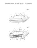
[0038] FIG. 1 is a perspective view of a temperature control device;
[0039] FIG. 2 is a sectional view of a temperature control device according to FIG. 1,
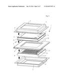
[0040] FIG. 3 is an exploded illustration of the temperature control device according to FIGS. 1 and 2;
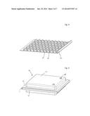
[0041] FIG. 4 is a perspective view of a surface-increasing element, which can be inserted in the flat tube, in order to increase the heat transfer from a fluid to the temperature control device;
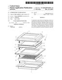
[0042] FIG. 5 is a perspective view of an alternative embodiment of a temperature control device;
[0043] FIG. 6 is a schematic view of a temperature control device, whereby in particular the different layers of the temperature control device are illustrated;
[0044] FIG. 7 is a perspective sectional view through a temperature control device according to FIG. 5;
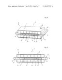
[0045] FIG. 8 is a perspective view of an alternative embodiment of a temperature control device;
[0046] FIG. 9 is a sectional view through a temperature control device according to FIG. 8;
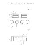
[0047] FIG. 10 is a schematic view of a temperature control device for the temperature control of an electronic component, such as, for example, a semiconductor;
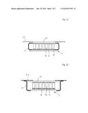
[0048] FIG. 11 is a sectional view through a thermoelectric module, whereby the module is limited laterally by a wall element;
[0049] FIG. 12 is a sectional view of an alternative embodiment of a thermoelectric module with an alternative embodiment of a laterally limiting wall element; and
[0050] FIG. 13 is a further sectional view of an alternative embodiment of a thermoelectric module with an alternative embodiment of a laterally limiting wall element.
DETAILED DESCRIPTION
[0051] FIG. 1 shows a perspective view of a temperature control device 1. Temperature control device 1 is substantially formed by a housing element 2, which is placed on a tube 3. FIG. 1 shows a temperature control device 1, which has a housing element 2 both on the top side and on the bottom side of tube 3. The following description is limited to the embodiment of the top area of temperature control device 1, the bottom area being made mirror symmetric to the top area.
[0052] Housing element 2 is formed cup-like and at its bottom end has a flange area 10, which is formed circumferential around the cup-like body of housing element 2. Flange area 10 serves as a connecting surface to tube 3.
[0053] A receiving area, in which a component 4 is inserted, is formed between tube 3 and housing element 2. Component 4 can be a thermoelectric module or another electrical or electronic component, for example.
[0054] Component 4 on a first wall 30 has two openings 5, through which electrical contacting of component 4 can occur. A connecting layer 7 is provided between first wall 30 and an inner surface of housing element 2. Said connecting layer 7 serves as the fluid-tight connection of component 4 to housing element 2. Advantageously, connecting layer 7 is formed by a silicone adhesive. The silicone adhesive offers the advantage that it can also absorb the mechanical disturbances and thermomechanical stress, thereby assuring a secure connection between component 4 and housing element 2.
[0055] Housing element 2 has a recess 6, which is arranged in the shape of a rectangle in the upward facing area of housing element 2. Recess 6 is covered completely by first wall 30 of component 4.
[0056] A first fluid 8 can flow through tube 3. A second fluid 9 can flow around temperature control device 1 as a whole.
[0057] FIG. 2 shows a section through temperature control device 1, which is already illustrated in FIG. 1.
[0058] The inner structure of component 4 can be seen in particular in FIG. 2. A plurality of thermoelectrically active materials 20 is arranged in the interior of component 4. These are formed in the shape of rectangles and arranged in rows parallel to one another. In each case, two adjacent thermoelectrically active materials 20 are connected to one another in an electrically conductive manner via a conductive bridge 21. In this way, the thermoelectrically active materials 20 arranged within component 4 are connected electrically in series to one another.
[0059] The thermoelectrically active materials 20 are connected via conductive bridges 21 to the opposite first walls 30 of component 4. Via conductive bridges 21 and first walls 30, a thermal exchange between the thermoelectrically active materials 20 and, for example, fluid 9 can occur outside temperature control device 1 or fluid 8 in the interior of tube 3.
[0060] It can be seen further in the section of FIG. 2 that connecting layer 7 is provided between first wall 30 and housing element 2. It runs completely around recess 6 and represents a fluid-tight connection between component 4 and housing element 2.
[0061] The bottom first wall 30 is also connected to an outer surface of tube 3. In an advantageous embodiment the connection can also be realized by a silicone adhesive, as a result of which a fluid-tight connection forms between tube 3 and the bottom first wall 30. A fluid-tight adhesion between tube 3 and the bottom first wall 30 is not absolutely necessary, however.
[0062] A hollow space filled with air, for example, and used for thermal insulation toward the outside, can form between the outer thermoelectrically active materials 20 and the inner surface of housing element 2.
[0063] A separation of first fluid 8, which flows through tube 3, and second fluid 9, which flows around the temperature control device 1 as a whole, results due to the fluid-tight connection between flange area 10 and outer surface of tube 3.
[0064] A plurality of fin elements 22 is shown in tube 3 of FIG. 2. These are cut out of a baseplate 23 and bent at a 90° angle. Baseplate 23 is arranged within a recess 26 of tube 3 at the first walls 30 of component 4. A connecting layer can be provided in each case between baseplate 23 and first wall 30.
[0065] In the illustration of FIG. 2, a baseplate 23 with fin elements 22 is arranged both on bottom component 4 and on top component 4. These are formed identical and arranged rotated to one another by 180° on the particular component 4.
[0066] Each of the baseplates 23 is angled at one of its end regions such that a thermal decoupling element is formed, which separates thermally a middle region of tube 3 from an edge region. In the exemplary embodiment of FIG. 2, this is achieved by bending of baseplate 23. A wall is produced as a result, which separates the central region of tube 3 from the lateral flow regions 25. The separation by thermal decoupling element 24 can be made fluid-tight but need not necessarily be fluid-tight. The thermally separated regions 25 are advantageously filled with air and thus form a thermal insulation toward the outside.
[0067] The first walls 30 can be advantageously made of a material such as silicon nitride or aluminum oxide or aluminum oxide/zirconium oxide or an aluminum nitride material or an alloy of the aforementioned materials. Housing element 2 can be advantageously made of an austenitic or ferritic stainless steel or of aluminum or of a plastic material. Tube 3 is also advantageously made of an austenitic or ferritic stainless steel or an aluminum material or a plastic material.
[0068] Fluid 8, which flows through tube 3, is advantageously the fluid with the higher temperature level. Accordingly, fluid 9, which has a lower temperature level in comparison to fluid 8, flows overall around temperature control device 1. This is particularly advantageous because connecting layer 7, which advantageously is a silicone adhesive, is thus not exposed to unnecessarily high temperatures.
[0069] The connection between housing element 2 and tube 3 in the area of flange 10 is advantageously made by laser welding. Fin elements 22 or baseplate 23 is advantageously connected by brazing or active metal brazing to first walls 30. Fin elements 22 or baseplate 23 and thermal decoupling element 24 is formed of stainless steel. Alternatively, other metallic materials can also be provided or a base material can be coated with a metallic coating.
[0070] Fin elements 22 of FIG. 2 are only exemplary. In alternative embodiments, for example, a corrugated fin element can also be placed in tube 3 or fastened in it.
[0071] In order to be able to create a permanent connection between fin elements 22 or baseplate 23 and first wall 30, it may also be necessary to coat or metallize first wall 30 on the side facing fin elements 22. To this end, it can be provided, for example, to apply a copper layer or a nickel layer or a copper-silver layer or a silver layer. Preferably nickel or alloys of silver and copper or titanium-based solder can be used for connection between first wall 30 and fins 22 or baseplate 23.
[0072] FIG. 3 shows an exploded illustration of temperature control device 1, as it is illustrated in FIGS. 1 and 2. The reference characters of the individual elements correspond to those used in FIGS. 1 and 2. In addition, a second wall 31 can be seen in FIG. 3, which in conjunction with first walls 30 closes component 4 in all spatial directions. Furthermore, a connecting layer allowing first wall 30 of component 4 to be connected to an outer surface of tube 3 is indicated by reference character 32.
[0073] FIG. 4 shows an illustration of the fin element, as has already been indicated in FIGS. 1 to 3. It is evident that the individual fin elements 22 are bent from a rectangular baseplate 23. To this end, the individual fin elements 22 are removed from baseplate 23, for example, by laser welding and bent upwards by approximately 90° with a mechanical forming process. A thermal decoupling element 24 is formed on the right lateral edge region of the fin element by bending a section upwards by 90°. This is used to separate the inner region of tube 3 in a flown-through region along fin elements 22 and an adjacent thermally separated region 25.
[0074] The fin element of FIG. 4 is an exemplary illustration. Designs different herefrom can also be provided in alternative embodiments.
[0075] FIG. 5 shows an alternative embodiment of a temperature control device 40. Housing element 41 in contrast to the illustrations in the preceding figures now has no recess and is also closed in the upward spatial direction. Electrical contacts 48 are indicated in this upward directed surface. Housing element 41 has a flange region 42, which in its realization corresponds substantially to flange region 10. Housing element 41 is connected to tube 3 via said flange region 42. The connecting layers and connecting methods correspond to those for the exemplary embodiments of FIGS. 1 to 3. Housing element 41 is also made cup-shaped.
[0076] FIG. 6 shows an exploded illustration in schematic form, which describes the basic structure of temperature control devices 1 or 40. A coating 44 is applied proceeding from tube 3, which forms the base in this view. Said coating 44 is advantageously a ceramic coating and thus represents an electrical insulation layer. Connecting layer 45, which is, for example, a brazing foil or a brazing paste, follows thereafter in the upward direction. A coating 46, which is applied to conductive bridges 21, follows on connecting layer 45. Coating 46 can be made, for example, of nickel or of silver or of gold or of a molybdenum-silver coating or a gold or silver mixture coating. A connecting layer 47, which is used for connecting the thermoelectrically active materials 20 to conductive bridges 21, follows on coating 46.
[0077] The thermoelectrically active materials 20, for example, can include a material such as cobalt-antimony or bismuth-antimony or bismuth-telluride or zinc-antimony or magnesium silicon or manganese silicon or of a silicon-based material. Combinations of the individual materials with one another are also possible.
[0078] The connection of thermoelectrically active materials 20 to conductive bridges 21 occurs, for example, via a welding or brazing or a sintering pressure process. For example, friction, diffusion, or resistance welding may be used as welding methods. Micro sintering or nano-silver paste sintering, for example, may be used as the sintering pressure process.
[0079] Conductive bridges 21 are advantageously made of a copper material or a molybdenum-copper material.
[0080] FIG. 7 shows a sectional view of temperature control device 40 of FIG. 5. It is evident in FIG. 7 that the structure of the interior of temperature control device 40 corresponds substantially to temperature control device 1.
[0081] Housing element 41 has no recess in the upward direction. In the interior of housing element 41, the thermoelectrically active materials or their conductive bridges 21 are connected directly without a first wall 30 to housing element 41. Downwards toward tube 3, below thermoelectrically active materials 20 or conductive bridges 21, a first wall 30 is again arranged, connecting them to tube 3, that also has recess 26.
[0082] Fin elements 22 or baseplates 23 and thermal decoupling elements 24, which divide the tube into a central flown-through region and into laterally thermally decoupled regions 25, are also arranged in the interior of tube 3.
[0083] FIG. 8 shows a further alternative embodiment of a temperature control device 50. This represents an improvement of temperature control device 40 shown in FIG. 7. As a departure from temperature control device 40, tube 3a now also no longer has a recess. Thermoelectrically active materials 20 or conductive bridges 21 can accordingly also be connected to tube 3a without a downward directed first wall 30.
[0084] In the exemplary embodiment of FIG. 8, thermoelectrically active materials 20 or conductive bridges 21 without supplementary walls are connected directly to top housing element 41 or to tube 3a. The inner structure of tube 3a corresponds to the inner structure of tube 3. The only difference between tube 3 and tube 3a is the missing recess 26.
[0085] FIG. 9 shows a sectional view of temperature control device 50 according to FIG. 8, whereby the sectional plane is perpendicular to the main flow direction of tube 3a. It is especially evident in FIG. 9 that thermoelectrically active materials 20 or conductive bridges 21 are connected directly to housing element 41 or tube 3a.
[0086] FIG. 10 shows an alternative design for a temperature control device 60. The basic structure corresponds to the structure of the preceding temperature control devices 1, 40, or 50.
[0087] A fluid, which advantageously flows through the circular flow channels indicated in FIG. 10, flows through temperature control device 60. A conductive bridge 63 is connected to an outer surface or border of said flow channels via a connecting layer 62. A plurality of coatings or connecting layers, labeled with reference characters 63 to 67, follows on conductive bridge 63. Coatings 63 to 67 in this case correspond to the already described metallic or ceramic coatings or connecting layers of the preceding exemplary embodiments.
[0088] Finally, a component 68 is connected to coating 67. Component 68 shown in FIG. 9 is, for example, a semiconductor, a silicon chip, or a microchip. A closing housing element, which is not shown in FIG. 10, however, can also be arranged around component 68.
[0089] FIG. 11 shows a section through component 4. In addition to a plurality of thermoelectrically active materials 20, connected together via conductive bridges 21, a connecting layer 71 is shown over which conductive bridges 21 are connected to first walls 30. A wall element 70 is provided laterally, which connects the opposite first walls 30 together. Component 4 is closed outwardly thermally and/or fluidically via wall element 70. To this end, a wall element 70 can be provided in each of the four lateral spatial directions. Wall element 70 in this case can be formed, for example, of a ceramic material. Likewise, a metallic material that is coated with a ceramic coating can be provided. Further, metallic materials can also be provided with metallic or ceramic coatings.
[0090] FIG. 12 shows a further alternative illustration of a wall element 72 for the lateral sealing of component 4. In FIG. 12, C-shaped wall elements 72 are provided for this purpose, positioned in such a way between first walls 30 that wall element 72 is opened in the direction of thermoelectrically active materials 20.
[0091] As also already described in FIG. 11, in FIG. 12 a plurality of said wall elements 72 can be arranged in the four lateral spatial directions as well, so that a totally thermal and/or fluidic sealing of component 4 can be achieved. Wall element 72 in this case can also be made of a ceramic or a metallic material, which can also be coated ceramically or metallically.
[0092] In FIG. 12, component 4 is connected upwardly to a housing element 2 or a tube 3. Housing element 2 or tube 3 is only indicated in FIG. 12.
[0093] FIG. 13 shows a further alternative embodiment of a wall element 73. Wall elements 73 of FIG. 13 are made S-shaped and are now arranged in such a way that they connect the bottom first wall 30 to an inner surface of housing element 2 or of tube 3. A sealing of component 4 arises here by a connection of the inner surfaces of tube 3 or of housing element 2 with first wall 30, facing away from the inner surface of component 4. Component 73 and components 70 or 72 can be made of ceramic or metallic materials and suitable coatings.
[0094] The exemplary embodiments in FIGS. 1 to 13 are provided as examples and are not restrictive in nature, particularly with respect to the geometric design of the exemplary embodiments and the choice of materials. All features of the individual exemplary embodiments can be combined with one another. The exemplary embodiments of FIGS. 1 to 13 are used for clarifying the inventive concept and are not restrictive in nature.
[0095] The invention being thus described, it will be obvious that the same may be varied in many ways. Such variations are not to be regarded as a departure from the spirit and scope of the invention, and all such modifications as would be obvious to one skilled in the art are to be included within the scope of the following claims.
User Contributions:
Comment about this patent or add new information about this topic:
Images included with this patent application:
 |  |
 |  |
 |  |
 |  |
| Similar patent applications: | |
| Date | Title |
|---|---|
| 2015-04-09 | Beverage cooling device |
| 2014-09-11 | Sample cooling device |
| 2015-02-26 | Screw compressor drive control |
| 2011-06-30 | Decompression device |
| 2012-03-15 | Gas treatment device |
| New patent applications in this class: | |
| Date | Title |
|---|---|
| 2018-01-25 | Heating and cooling cup holder |
| 2016-12-29 | Temperature control unit for a gaseous or liquid medium |
| 2016-07-07 | Solar cooling system |
| 2016-06-23 | Temperature maintaining case |
| 2016-05-19 | Cooling and heating cup holder |
| New patent applications from these inventors: | |
| Date | Title |
|---|---|
| 2022-03-31 | Cooling device and electromagnetic induction charging device |
| 2022-03-31 | Ground assembly for an inductive charging device |
| 2017-06-15 | Thermoelectrical device |
| 2016-03-31 | Thermoelectric generator, in particular for a motor vehicle |
| 2015-11-12 | Thermoelectric generator |
| Top Inventors for class "Refrigeration" | |
| Rank | Inventor's name |
|---|---|
| 1 | Michael F. Taras |
| 2 | Alexander Lifson |
| 3 | Koji Yamashita |
| 4 | Hiroyuki Morimoto |
| 5 | Patrick J. Boarman |