Patent application title: APPARATUS INCLUDING CARRIER-NESTING ASSEMBLY FOR INFANT CARRIER
Inventors:
Joe Carl Strickland (Jamestown, CO, US)
IPC8 Class: AA47D1302FI
USPC Class:
224158
Class name: Package and article carriers carried by animate bearer carrier for person
Publication date: 2014-11-27
Patent application number: 20140346200
Abstract:
An apparatus for an infant carrier configured to carry an infant therein.
The apparatus comprises: a handle assembly; and a carrier-nesting
assembly. The carrier-nesting assembly is configured to: receivably and
supportably nest the infant carrier; and couple with the handle assembly
in such a way that once the handle assembly is extended away from the
infant carrier received by the carrier-nesting assembly, the
carrier-nesting assembly is configured to provide an instance of a
junction of branch members located on opposite sides of the infant
carrier. A weight of the infant carrier and of the infant received in the
infant carrier is safely supported by the carrier-nesting assembly once
the carrier-nesting assembly is set apart from the ground. Instances of
the junction of branch members that are formed by the carrier-nesting
assembly improve lateral stability of the infant carrier.Claims:
1. An apparatus for accommodating an infant carrier, comprising: a handle
assembly; and a carrier-nesting assembly comprising opposing branch
members disposable on opposing sides of the infant carrier, the
carrier-nesting assembly configured to: couple with the handle assembly,
receivably and supportably nest the infant carrier by way of the opposing
branch members, and instantaneously junction the opposing branch members
by extending the handle assembly away from the infant carrier, whereby
lateral stability, vertical support, and safety of the infant carrier are
enhanced.
2. The apparatus of claim 1, wherein the carrier-nesting assembly is configured to extend, at least in part, away from each of the opposing sides of the infant carrier.
3. The apparatus of claim 1, wherein the carrier-nesting assembly is configured to securely extend, at least in part, underneath the infant carrier and along a length of each of the opposing sides thereof.
4. The apparatus of claim 1, wherein the handle assembly is configured to: extend toward the opposite sides of the infant carrier, and couple to a portion of the carrier-nesting assembly, the portion disposed proximate to an apex region of a junction of the opposing branch members.
5. (canceled)
6. The apparatus of claim 1, wherein the handle assembly comprises a first strap mechanism having opposing end portions each configured to couple with the carrier-nesting assembly.
7. The apparatus of claim 6, wherein the carrier-nesting assembly comprises a second strap mechanism having opposing end sections configured to selectively and securely couple with a respective one of the opposing end portions of the first strap mechanism, the second strap mechanism securely extendable underneath the infant carrier at a foot portion thereof.
8. The apparatus of claim 7, wherein the carrier-nesting assembly further comprises a third strap mechanism having opposing end portions configured to selectively and securely couple with a respective one of the opposing end portions of the first strap mechanism, the third strap mechanism securely extendable underneath the infant carrier at a head portion thereof, and the third strap mechanism spaced apart from the second strap mechanism.
9. The apparatus of claim 8, wherein at least one of the first strap mechanism, the second strap mechanism, and the third strap mechanism comprises, at least in part, a flexible material.
10. The apparatus of claim 8, wherein the second strap mechanism and the third strap mechanism, in combination, instantaneously tension the opposing branch members by extending the handle assembly away from the infant carrier.
11. The apparatus of claim 1, wherein the handle assembly comprises a first joint mechanism disposable at one side of the infant carrier.
12. The apparatus of claim 11, wherein the handle assembly further comprises a second joint mechanism disposable at an opposite side of the infant carrier and spaceable-apart from the first joint mechanism.
13. The apparatus of claim 12, wherein the handle assembly further comprises a first strap mechanism having opposing end portions configured to selectively and securely couple with a respective one of the first joint mechanism and the second joint mechanism.
14. The apparatus of claim 13, wherein the carrier-nesting assembly comprises a second strap mechanism having opposing end portions configured to selectively and securely couple with a respective one of the first joint mechanism and the second joint mechanism, the second strap mechanism configured to securely extend underneath the infant carrier at a foot portion and along a length of each of the opposing sides thereof.
15. The apparatus of claim 14, wherein the carrier-nesting assembly further comprises a third strap mechanism having opposing end portions configured to selectively and securely couple with a respective one of the first joint mechanism and the second joint mechanism, the third strap mechanism configured to extend securely underneath the infant carrier at a head portion and along a length of each of the opposing sides thereof, and the third strap mechanism spaceable-apart from the second strap mechanism.
16. The apparatus of claim 1, wherein the carrier-nesting assembly comprises a fastener assembly configured to securely and positionally attach, at least in part, the carrier-nesting assembly to the infant carrier.
17. The apparatus of claim 1, wherein the carrier-nesting assembly comprises a fastener assembly configured to securely and positionally attach, at least in part, to the infant carrier, and wherein the fastener assembly comprises: a first touch fastener; and a second touch fastener positionable relative to the first touch fastener, the second touch fastener coupled with the infant carrier, the carrier-nesting assembly positionable over the second touch fastener; and the first touch fastener positionable for coupling with the second touch fastener and for covering, at least in part, both the carrier-nesting assembly and the second touch fastener, and wherein the first touch fastener positionally secures the carrier-nesting assembly with the second touch fastener.
18. The apparatus of claim 1, wherein the carrier-nesting assembly comprises a fastener assembly configured to positionally attach, at least in part, to the infant carrier, wherein the fastener assembly comprises: a first positioning tab; and a second positioning tab, the first positioning tab providing first slots in relation to a body of the infant carrier; the second positioning tab providing second slots in relation to the body of the infant carrier; and the first slots and the second slots configured to accommodate positional insertion of the carrier-nesting assembly, wherein the carrier-nesting assembly remains, at least in part, positionally secured to the infant carrier.
19. (canceled)
20. An enhanced infant carrier system, comprising: an apparatus for accommodating an infant carrier, comprising: a handle assembly; and a carrier-nesting assembly comprising opposing on opposing sides of the infant carrier, the carrier-nesting assembly configured to: couple with the handle assembly, receivably and supportably nest the infant carrier by way of the opposing branch members, and instantaneously junction the opposing branch members extending the handle assembly away from the infant carrier, whereby lateral stability, vertical support, and safety of the infant carrier are enhanced; and an infant carrier configured to operatively couple with the apparatus.
21. The apparatus of claim 21, further comprising a plurality of positioning tabs disposed in a manner that facilitates unhindered access to a latching mechanism and to a plurality of adjustment features for the straps that secure the infant to the carrier.
22. The apparatus of claim 21, wherein the plurality of positioning tabs is disposed in relation to a front portion and a rear portion of the carrier, whereby a point load and a mechanical stress is eliminated.
Description:
BACKGROUND OF THE INVENTION
[0001] 1. Field of the Invention
[0002] The present invention is in the technical field of infant carriers configured for transporting babies. More particularly, the present invention pertains to the field of an apparatus configured to receivably and supportably nest an infant carrier.
[0003] 2. Description of Related Art
[0004] Baby-transport devices are used for transporting children. These devices may be divided between wheeled devices, slings and backpacks, baskets, infant car seats and bicycle carriers. The larger and heavier perambulators or prams were replaced by lighter and more flexible designs. Wheeled devices are generally divided into prams or baby carriages used for newborn infants that normally rest facing downwardly. Strollers are used for the small child up to about three years old in a sitting position facing forward. Some strollers are configured to fold, whereas the buggy refers to a covered, non-folding transport. The infant car seat can be used to carry a baby within a car. Bicycles can be fitted with a bicycle trailer or a children's bicycle seat to carry infants and small children. All of the above-mentioned devices are examples of an infant carrier.
SUMMARY
[0005] The scope of the present invention is defined solely by the appended claims and the statements within this summary, and the scope of the invention is not affected to any degree by the statements within the detailed description of a preferred embodiment. In addressing many of the problems experienced in the related art, such as those relating to conventional infant carriers, the present disclosure generally involves the following aspects outlined below:
[0006] The present invention is directed towards an apparatus for an infant carrier configured to carry an infant therein. The apparatus comprises a handle assembly, and a carrier-nesting assembly. The carrier-nesting assembly is configured to: receivably and supportably nest the infant carrier; and couple with the handle assembly in such a way that once the handle assembly is extended away from the infant carrier received by the carrier-nesting assembly, the carrier-nesting assembly is configured to provide an instance of a junction of branch members located on opposite sides of the infant carrier. The weight of the infant carrier and of the infant received in the infant carrier is safely supported by the carrier-nesting assembly once the carrier-nesting assembly is set apart from the ground. Instances of the junction of branch members that are formed by the carrier-nesting assembly improve lateral stability of the infant carrier.
[0007] The present invention is directed towards a method of operating an infant carrier configured to carry an infant therein. The method comprises (the steps of): receiving and supportably nesting the infant carrier in a carrier-nesting assembly; coupling a handle assembly to the carrier-nesting assembly; and extending the handle assembly away from the infant carrier so that the carrier-nesting assembly provides an instance of a junction of branch members located on opposite sides of the infant carrier. The weight of the infant carrier and of the infant received in the infant carrier is safely supported by the carrier-nesting assembly once the carrier-nesting assembly is set apart from the ground. Instances of the junction of branch members that are formed by the carrier-nesting assembly improve lateral stability of the infant carrier.
[0008] The present invention is directed towards an apparatus, comprising an infant carrier configured to carry an infant therein, a handle assembly, and a carrier-nesting assembly. The carrier-nesting assembly is configured to: receivably and supportably nest the infant carrier; and couple with the handle assembly in such a way that once the handle assembly is extended away from the infant carrier received by the carrier-nesting assembly, the carrier-nesting assembly is configured to provide an instance of a junction of branch members located on opposite sides of the infant carrier. The weight of the infant carrier and of the infant received in the infant carrier is safely supported by the carrier-nesting assembly once the carrier-nesting assembly is set apart from the ground. Instances of the junction of branch members that are formed by the carrier-nesting assembly improve lateral stability of the infant carrier.
[0009] In general, the present disclosure involves devices and methods that provide many beneficial features and advantages over the related art devices and methods, including, but not limited to the following.
OBJECTS AND ADVANTAGES
[0010] The present disclosure can provide a number of advantages depending on the particular aspect, embodiment, and/or configuration. None of the particular objects or advantages that follow must be entirely satisfied as they are non-exclusive alternatives and at least one of the following objects is met; accordingly, several objects and advantages of the present invention are (and are not limited to):
[0011] (a) to provide a means for the weight of the infant carrier and of the infant received in the infant carrier to be safely supported by a carrier-nesting assembly of the apparatus 100 once the carrier-nesting assembly is set apart from the ground;
[0012] (b) to provide a means for instances of a junction of branch members that are formed by the carrier-nesting assembly to improve lateral stability of the infant carrier;
[0013] (c) to provide a means for allowing a user to not inadvertently wake up the infant by the act of unstrapping the infant from the car seat and resettling the infant into the infant carrier;
[0014] (d) to provide a means for allowing transfer and transport of the infant undisturbed, in a more safe and comfortable manner;
[0015] (e) to provide a means for providing an apparatus that takes up very little cargo storage space, weighs very little, and is relatively easy to deploy;
[0016] (f) to provide a means for permitting the infant carrier to become self-stabilizing; as well, the infant carrier does not tip for the case where the apparatus self-adjusts;
[0017] (g) to provide a means for providing the user the ability to simultaneously carry the infant, and hold an older toddler's hand and escort him safely through the streets;
[0018] (h) to provide a means for freeing up the use of both hands (of the user) without having to set the infant carrier on the floor or balance it on a counter, and frees up both hands for any number of other everyday tasks;
[0019] (i) to provide a means for improving movement of the infant carrier without fear of the infant carrier shifting, anywhere in a 160 degree arc around the body of the user;
[0020] (j) to provide a means for permitting hands-free operation of the infant carrier from approximately in front of the user, through all side carry positions, to a fully behind carry position (relative to the front of the user);
[0021] (k) to provide a means for adjusting for either right or left hand users;
[0022] (l) to provide a means for few (or no) modifications or alterations to the physical or functional integrity of the infant carrier are required (if so desired); and
[0023] (m) to provide a means for no mechanical, chemical or functional impairments to the infant carrier as a result of installing or using the apparatus.
[0024] These and other objectives and advantages of the instant invention will become apparent from the following description taken in conjunction with the accompanying drawings wherein are set forth, by way of illustration and example, certain embodiments of the instant invention. The drawings are intended to constitute a part of this specification and include exemplary embodiments of the present invention and illustrate various objects and features thereof.
BRIEF DESCRIPTION OF THE DRAWINGS
[0025] The above, and other, aspects, features, and advantages of several embodiments of the present disclosure will be more apparent from the following Detailed Description as presented in conjunction with the following several figures of the Drawing.
1. FIGURES
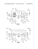
[0026] FIG. 1 (Sheet 1) illustrates a perspective side view from underneath an apparatus, in accordance with an embodiment of the present disclosure.
[0027] FIG. 2 (Sheet 1) illustrates a perspective side view from above the apparatus of FIG. 1, in accordance with an embodiment of the present disclosure.
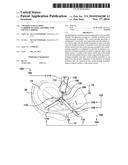
[0028] FIG. 3 (Sheet 2) illustrates a perspective view of a front-end section of the apparatus of FIG. 1, in accordance with an embodiment of the present disclosure.
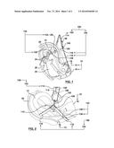
[0029] FIG. 4 (Sheet 2) illustrates another perspective view of the front end of the apparatus of FIG. 1, in accordance with an embodiment of the present disclosure.
[0030] Corresponding reference characters indicate corresponding components throughout the several figures of the Drawings. Elements in the several figures are illustrated for simplicity and clarity and have not necessarily been drawn to scale. For example, the dimensions of some of the elements in the figures may be emphasized relative to other elements for facilitating understanding of the various presently disclosed embodiments. In addition, common, but well-understood, elements that are useful or necessary in commercially feasible embodiment are often not depicted in order to facilitate a less obstructed view of these various embodiments of the present disclosure.
2. REFERENCES
[0031] infant carrier 10
[0032] sides 12
[0033] head portion 14
[0034] foot portion 16
[0035] lateral sides 18
[0036] carrier handle assembly 20
[0037] carrier base 22
[0038] carrier stands 24
[0039] pass-through carrier groove 26
[0040] buckle 28
[0041] apparatus 100
[0042] handle assembly 102
[0043] carrier-nesting assembly 104
[0044] junction of branch members 106
[0045] first joint mechanism 110
[0046] second joint mechanism 112
[0047] first strap mechanism 114
[0048] second strap mechanism 116
[0049] third strap mechanism 118
[0050] clip mechanism 120
[0051] fastener assembly 122
[0052] first touch fastener 124
[0053] second touch fastener 126
[0054] first positioning tab 128
[0055] second positioning tab 130
DETAILED DESCRIPTION
[0056] The following description is not to be taken in a limiting sense, but is made merely for the purpose of describing the general principles of exemplary embodiments, many additional embodiments of this invention are possible. It is understood that no limitation of the scope of the invention is thereby intended. The scope of the disclosure should be determined with reference to the Claims. Reference throughout this specification to "one embodiment," "an embodiment," or similar language means that a particular feature, structure, or characteristic that is described in connection with the embodiment is included in at least one embodiment of the present disclosure. Thus, appearances of the phrases "in one embodiment," "in an embodiment," and similar language throughout this specification may, but do not necessarily, all refer to the same embodiment.
[0057] Further, the described features, structures, or characteristics of the present disclosure may be combined in any suitable manner in one or more embodiments. In the Detailed Description, numerous specific details are provided for a thorough understanding of embodiments of the disclosure. One skilled in the relevant art will recognize, however, that the embodiments of the present disclosure can be practiced without one or more of the specific details, or with other methods, components, materials, and so forth. In other instances, well-known structures, materials, or operations are not shown or described in detail to avoid obscuring aspects of the present disclosure. Any alterations and further modifications in the illustrated devices, and such further application of the principles of the invention as illustrated herein are contemplated as would normally occur to one skilled in the art to which the invention relates.
[0058] Unless otherwise indicated, the drawings are intended to be read (e.g., arrangement of parts, proportion, degree, etc.) together with the specification, and are to be considered a portion of the entire written description of this invention. As used in the following description, the terms "horizontal", "vertical", "left", "right", "up" and "down", as well as adjectival and adverbial derivatives thereof (e.g., "horizontally", "rightwardly", "upwardly", etc.), simply refer to the orientation of the illustrated structure as the particular drawing figure faces the reader. Similarly, the terms "inwardly" and "outwardly" generally refer to the orientation of a surface relative to its axis of elongation, or axis of rotation, as appropriate.
[0059] The phrases "at least one," "one or more," and "and/or" are open-ended expressions that are both conjunctive and disjunctive in operation. For example, each of the expressions "at least one of A, B and C", "at least one of A, B, or C", "one or more of A, B, and C", "one or more of A, B, or C" and "A, B, and/or C" means A alone, B alone, C alone, A and B together, A and C together, B and C together, or A, B and C together. The terms "a" or "an" entity refers to one or more of that entity. As such, the terms "a" (or "an"), "one or more" and "at least one" can be used interchangeably herein. It is also to be noted that the terms "comprising," "including," and "having" can be used interchangeably.
[0060] For the purposes of promoting an understanding of the principles of the present invention, reference will now be made to the embodiments illustrated in the drawings and specific language will be used to describe the same.
[0061] Generally speaking, with reference to FIGS. 1, 2, 3, and 4, there are depicted examples of an apparatus 100 for an infant carrier 10.
[0062] According to a first option, the apparatus 100 is for an infant carrier 10 configured to carry an infant therein. The apparatus 100 comprises a handle assembly 102, and a carrier-nesting assembly 104. The carrier-nesting assembly 104 is configured to receivably and supportably nest the infant carrier 10. In addition, the carrier-nesting assembly 104 is also configured to couple with the handle assembly 102 in such a way that once the handle assembly 102 is extended away from the infant carrier 10 that is received by the carrier-nesting assembly 104, the carrier-nesting assembly 104 provides (and/or forms) an instance of a junction of branch members 106 that is located on opposite sides 12 of the infant carrier 10. Several advantages arise from using the apparatus 100, such as (and not limited to): (A) the weight of the infant carrier 10 and of the infant received in the infant carrier 10 is safely supported by the carrier-nesting assembly 104 once the carrier-nesting assembly 104 is set apart from the ground, and/or (B) instances of the junction of branch members 106 that are formed by the carrier-nesting assembly 104 improve lateral stability of the infant carrier 10.
[0063] It is understood that the definition of "couple" in this Specification includes any coupling means configured to directly couple and/or to indirectly couple (join or connect or link) items or components together (either permanently or not permanently)
[0064] It is understood that according to the first option, the apparatus 100 does not include the infant carrier 10; in this way, the infant carrier 10 may be provided by the user (for example), and the apparatus 100 may be provided by a manufacturer or supplier (this option is considered the aftermarket case).
[0065] Generally speaking, the junction of branch members 106 may include a fork formation and/or a branching shape and/or a crotch shape. The junction of branch members 106 includes (for example) a space between elements (lines, members, straps or planes) that intersect. The junction of branch members 106 includes an inclination of one element to another element. For example, the junction of branch members 106 may be configured to provide (or form) an inverted "V" formation, a triangular geometry, and/or any suitable shape and/or size that satisfies the definition of the junction of branch members 106, and/or any functional or structural equivalent thereof. By way of example, the carrier-nesting assembly 104 may include an arrangement of four straps (in which each strap is connected at positions (four points) extending proximate or toward each corner of the infant carrier 10; the opposite pairs of straps (positioned on opposite sides 12 of the infant carrier 10) form the junction of branch members 106 in such a way that the carrier-nesting assembly 104 provide, at least in part, lateral and/or longitudinal stability to the infant carrier 10.
[0066] In accordance with a second option, the apparatus 100 includes (and is not limited to) a combination of the infant carrier 10, the handle assembly 102, and the carrier-nesting assembly 104. It is understood that according to the second option, the apparatus 100 includes the infant carrier 10; for the second option, the apparatus 100 may be provided by a manufacturer (for example); this option may be used for the case where a manufacturer desires to supply both the infant carrier 10 and the apparatus 100 in combination to the user. It will be appreciated that instances of the apparatus 100 may fit on most existing infant carriers currently in the market as a retrofit device.
[0067] In accordance with a third option, the apparatus 100 is for the infant carrier 10 and for the handle assembly 102. The apparatus 100 includes (and is not limited to) the carrier-nesting assembly 104. It is understood that according to the third option, the apparatus 100 does not include the infant carrier 10 and does not include the handle assembly 102; for the third option, the infant carrier 10 and the handle assembly 102 may be provided by the user (for example), and the apparatus 100 may be provided by the manufacturer.
[0068] The following describes the options (also known as variations, alternatives, or modifications) of the apparatus 100 regardless of whether or not the following description identifies whether any such option is explicitly labeled or not explicitly labeled as such.
[0069] A specific includes the carrier-nesting assembly 104 configured to couple with the handle assembly 102 in such a way that once: (A) the carrier-nesting assembly 104 supportably nests the infant carrier 10, (B) the carrier-nesting assembly 104 and the handle assembly 102 are attached to each other, and (C) the handle assembly 102 is manually extended away from the infant carrier 10, then the carrier-nesting assembly 104 provides (or forms) an instance of the junction of branch members 106.
[0070] For instance, other options may include: (A) the junction of branch members 106 intersects at a point and defines (or forms) an angle therebetween (that is, defines the angle between at least two members of the junction of branch members 106), (B) the junction of branch members 106 are symmetrically positioned relative to each other at the opposite sides 12 of the infant carrier 10, (C) each angle defined by the junction of branch members 106 is spaced apart from each other across the opposite sides 12, and/or (D) each angle formed by the junction of branch members 106 are symmetrically positioned relative to each other at the opposite sides 12 of the infant carrier 10.
[0071] In accordance with an option, as depicted in FIGS. 1 and 2, once the handle assembly 102 is extended away from the infant carrier 10, the instances of the junction of branch members 106 are spaced apart (or located away) from the infant carrier 10. Instances of the junction of branch members 106 are positioned on opposite sides 12 of the infant carrier 10.
[0072] In accordance with an option, as depicted in FIGS. 1 and 2, the carrier-nesting assembly 104 is configured to extend, at least in part, away from each of the opposite sides 12 of the infant carrier 10.
[0073] In accordance with an option, as depicted in FIGS. 1 and 2, the carrier-nesting assembly 104 is configured to securely extend underneath (along a back wall portion of) the infant carrier 10 and along a length of each of the opposite sides 12 of the infant carrier 10.
[0074] In accordance with an option, as depicted in FIGS. 1 and 2, the handle assembly 102 is configured to extend toward the opposite sides 12 of the infant carrier 10. The handle assembly 102 is also configured to couple to a portion of the carrier-nesting assembly 104. The portion is located proximate to an apex region of the junction of branch members 106. The apex is defined as a vertex, a pinnacle or a high point of the junction of branch members 106.
[0075] According to the example depicted in FIGS. 1 and 2, generally speaking, the infant carrier 10 includes opposite sides 12, a head portion 14, a foot portion 16 spaced apart from the head portion 14, and opposite lateral sides 18. The opposite lateral sides 18 extend between the head portion 14 and the foot portion 16. The instances of the opposite lateral sides 18 are set apart from each other. It will be appreciated that the opposite sides 12 of the infant carrier 10 includes any selected one of: (A) the head portion 14 and the foot portion 16, and/or (B) the opposite lateral sides 18. The head portion 14 is generally configured to support the head of the infant received in the infant carrier 10. The foot portion 16 is generally configured to support the legs of the infant received in the infant carrier 10. The head portion 14 and the foot portion 16 are configured to be rotatably and orientably positionable relative to each other so as to accommodate a desired orientation of the infant in the infant carrier 10. For example, the head portion 14 and the foot portion 16 are orientable relative to each other so as to provide (or to form) an angle therebetween. More specifically, the head portion 14 and the foot portion 16 are configured to be rotatably orientably positionable relative to each other so as to provide (or to form) an angle from between approximately 180 degrees to approximately 90 degrees. In addition, the infant carrier 10 also includes a carrier base 22, and carrier stands 24 extending from the carrier base 22. The carrier stands 24 are configured to support the carrier base 22 on a substantially horizontal surface. As depicted in FIG. 1, the carrier stands 24 define a pass-through carrier groove 26 that extends therethrough. In addition, the infant carrier 10 also includes a carrier handle assembly 20 that is operatively and pivotally mounted (movable) to the lateral sides 18 of the infant carrier 10. The carrier handle assembly 20 is generally U-shaped. The carrier handle assembly 20 is configured to be selectively pivotally rotatable (relative to the infant carrier 10) between a storage position (as depicted in FIG. 2) to a deployed position (not depicted) in order to suit the needs of the user. In the deployed position, the carrier handle assembly 20 is oriented or aligned (and spaced apart from) generally through the area of the junction of branch members 106. More specifically, the carrier handle assembly 20 is pivotally attached to the opposite lateral sides 18 of the infant carrier 10. Generally, the carrier-nesting assembly 104 is positioned, at least in part, between the body of the infant carrier 10 and the carrier handle assembly 20, for improved lateral stability of the infant carrier 10.
[0076] In accordance with an option, as depicted in FIGS. 1 and 2, the handle assembly 102 includes a first strap mechanism 114 having opposite end portions each configured to couple to the carrier-nesting assembly 104. The first strap mechanism 114 is configured to be lengthwise adjustable so as to accommodate the different physical requirements of different users. For instance, a buckle 28 may be positioned on the first strap mechanism 114, and the buckle 28 is configured to adjust a length of the first strap mechanism 114. Alternatively, the first strap mechanism 114 is configured to have a fixed longitudinal length (if so desired). The handle assembly 102 may include a shoulder pad configured to be centrally positioned on the first strap mechanism 114, and is also configured to facilitate improved user comfort for the case where the user places the handle assembly 102 on the shoulder area of the user. The handle assembly 102 may be configured to be disconnectable from the carrier-nesting assembly 104 and stowed away if so desired when not required or used, or when the infant carrier 10 is reattached to a base for travel in a vehicle (as a safety consideration). The handle assembly 102, when not in use, may be placed over and past (at least in part) the head portion 14 or the foot portion 16 of the infant carrier 10, so that the handle assembly 102 does not rest on the infant received in the infant carrier 10. In that case, the handle assembly 102 may drop down (at least in part) outside the body of the infant carrier 10, safely positioned (well away) from the infant. For the case where infant carrier 10 is secured (fixedly attached) in position in a vehicle, the handle assembly 102 is not required, and the handle assembly 102 may be detached (un-snapped) from the apparatus 100, and stored in a safe (secure) place; the carrier-nesting assembly 104 should not present a safety hazard to the infant since the carrier-nesting assembly 104 does not extend too far from the infant carrier 10 toward the infant. It is understood that all loose objects in a vehicle or automobile are to be secured so as to prevent the loose objects from becoming dangerous hazards during an unwanted vehicle collision or rollover accident. For the case where the apparatus 100 and the infant carrier 10 are taken through airport security, the handle assembly 102 may be tucked away into an empty instance of the infant carrier 10 when going through security, and the apparatus 100 and the infant carrier 10 may be treated as any other carry-on airline baggage. By way of example (and not limited thereto), the first strap mechanism 114 includes a flexible material, such as a web-belt material, a canvas-based material, a rip-stop nylon material, or any equivalent thereof in any suitable combination and permutation thereof (if so desired). The flexible material is a material that is capable of being bent or flexed, is capable of being pliable, and/or is capable of being bent repeatedly without injury or damage to the flexible material. In addition, the handle assembly 102 may include a pouch assembly (not depicted) configured to be connected to the handle assembly 102. The pouch assembly is also configured to securely receive user accessories (if so desired).
[0077] According to the example depicted in FIG. 2, the opposite end portions of the first strap mechanism 114 each include an instance of a clip mechanism 120 configured to connect to the first strap mechanism 114. Each instance of the clip mechanism 120 is also configured to selectively clip the first strap mechanism 114 to a respective one of a first joint mechanism 110 and to a second joint mechanism 112. The first joint mechanism 110 and the second joint mechanism 112 may include, for example, a metal ring of any suitable shape or any equivalent structure thereof (such as a D-ring).
[0078] In accordance with an option, as depicted in FIGS. 1 and 2, the carrier-nesting assembly 104 includes a second strap mechanism 116 having opposite end sections each of which are configured to selectively securely couple with a respective one of the opposite end portions of the first strap mechanism 114. The second strap mechanism 116 securely extends underneath (a backside of) the infant carrier 10 at the foot portion 16 of the infant carrier 10. "Selectively securely couple" means that the first strap mechanism 114 and the second strap mechanism 116 may be operated between: (A) a coupled-together condition and (B) decoupled-from-each-other condition (as may be required or selected by the user). The second strap mechanism 116 may be configured to be lengthwise adjustable in order to accommodate a variety of infant carriers already deployed. Alternatively, the second strap mechanism 116 is configured to have a fixed longitudinal length if so desired, perhaps for the case where the second strap mechanism 116 is deployed for a specific type of infant carrier. For example, the second strap mechanism 116 may include a pouch assembly configured to be connected to the second strap mechanism 116, and also configured to securely receive accessories. The second strap mechanism 116 may include a web-belt material, a canvas-based material, a rip-stop nylon material, or any equivalent thereof in any suitable combination and permutation thereof (if so desired).
[0079] In accordance with an option, as depicted in FIGS. 1 and 2, the carrier-nesting assembly 104 further includes a third strap mechanism 118 having opposite end parts each of which are configured to selectively securely couple with a respective one of the opposite end portions of the first strap mechanism 114. The third strap mechanism 118 extends securely underneath (a backside of) the infant carrier 10 at the head portion 14 of the infant carrier 10. The third strap mechanism 118 spaced apart from the second strap mechanism 116. The third strap mechanism 118 is configured to be lengthwise adjustable in order to accommodate a variety of infant carriers already deployed. The third strap mechanism 118 is configured to have a fixed longitudinal length, if so desired, perhaps for the case where the third strap mechanism 118 is deployed for a specific type of infant carrier. The third strap mechanism 118 may include a pouch assembly configured to be connected to the third strap mechanism 118, and also being configured to securely receive accessories. The third strap mechanism 118 may include a web-belt material, a canvas-based material, a rip-stop nylon material, or any equivalent thereof in any suitable combination and permutation thereof, if so desired to suit a particular need or application. Generally, any one of the first strap mechanism 114, the second strap mechanism 116, and the third strap mechanism 118 each includes, at least in part, a flexible material.
[0080] In accordance with an option, as depicted in FIGS. 1 and 2, once the handle assembly 102 is extended away from the infant carrier 10, the second strap mechanism 116 and the third strap mechanism 118 in combination form the instances of the junction of branch members 106. Other options are possible for specific components of the carrier-nesting assembly 104 used for providing (forming) the junction of branch members 106.
[0081] In accordance with an option, as depicted in FIGS. 1 and 2, the handle assembly 102 includes a first joint mechanism 110 configured for location (or placement) at one side of the infant carrier 10. It will be appreciated that the first joint mechanism 110 may include any suitable structure, such as a metal ring structure (D-ring) of any suitable shape and size, and any equivalent thereof (as may be required to suit a particular application or purpose).
[0082] In accordance with an option, as depicted in FIGS. 1 and 2, the handle assembly 102 further includes a second joint mechanism 112 configured for location at an opposite side of the infant carrier 10. The second joint mechanism 112 is also configured for a spaced-apart relationship with the first joint mechanism 110.
[0083] In accordance with an option, as depicted in FIGS. 1 and 2, the handle assembly 102 further includes a first strap mechanism 114 having opposite end portions each of which are configured to selectively securely couple with a respective one of the first joint mechanism 110 and the second joint mechanism 112. For example, the first strap mechanism 114 includes an instance of a clip mechanism 120 having a security latch. Each instance of the clip mechanism 120 is operatively securely coupled or connected to a respective end section of the first strap mechanism 114. Each of the first joint mechanism 110 and the second joint mechanism 112 includes an instance of a ring structure each operatively securely coupled or connected to a respective end section of the second strap mechanism 116 and to a respective end section of the third strap mechanism 118. Each instance of the clip mechanism 120 is configured to selectively securely latch to and to de-latch from the first joint mechanism 110 or from the second joint mechanism 112. For the case where the first strap mechanism 114 is not required, the clip mechanism 120 allows removal of the first strap mechanism 114 from the second strap mechanism 116 and from the third strap mechanism 118. For the case where it is not desired to have the first strap mechanism 114 be removable, the clip mechanism 120 is not provided, and first strap mechanism 114 is fixedly attached (directly or indirectly) to the second strap mechanism 116 and to the third strap mechanism 118. This option may lower manufacturing costs.
[0084] In accordance with an option, as depicted in FIGS. 1 and 2, the carrier-nesting assembly 104 includes a second strap mechanism 116 having opposite end sections each of which are configured to selectively securely couple with a respective one of the first joint mechanism 110 and the second joint mechanism 112. The second strap mechanism 116 is configured to securely extend underneath the infant carrier 10 at the foot portion 16 of the infant carrier 10 and along a length of each of the opposite sides 12 of the infant carrier 10.
[0085] In accordance with an option, as depicted in FIGS. 1 and 2, the carrier-nesting assembly 104 further includes a third strap mechanism 118 having opposite end parts being configured to selectively securely couple with a respective one of the first joint mechanism 110 and the second joint mechanism 112. The third strap mechanism 118 is configured to extend securely underneath the infant carrier 10 at the head portion 14 of the infant carrier 10 and along a length of each of the opposite sides 12 of the infant carrier 10. The third strap mechanism 118 is configured for spaced-apart relationship with the second strap mechanism 116.
[0086] Generally speaking, in accordance with an option, as depicted in FIGS. 3 and 4, the carrier-nesting assembly 104 includes a fastener assembly 122 configured to securely positionally attach, at least in part, the carrier-nesting assembly 104 to the infant carrier 10.
[0087] In accordance with an option, as depicted in FIG. 3, the fastener assembly 122 includes a first touch fastener 124, and a second touch fastener 126. The second touch fastener 126 is positionable relative to the first touch fastener 124. The second touch fastener 126 is coupled to the infant carrier 10. The carrier-nesting assembly 104 is positionable over the second touch fastener 126. The first touch fastener 124 is configured to be positioned so as to couple to the second touch fastener 126, and so as to cover, at least in part, both the carrier-nesting assembly 104 and the second touch fastener 126 in such a way that the first touch fastener 124 positionally secures the carrier-nesting assembly 104 to the second touch fastener 126.
[0088] For the case, as depicted in FIG. 3, where the apparatus 100 is sold or is provided to the after-market (that is, sold to users of existing infant carriers), the apparatus 100 may include an example of a fastener assembly 122 configured to positionally secure (positionally fix, attach), at least in part, the carrier-nesting assembly 104 to the infant carrier 10; as specifically depicted in FIG. 3, the fastener assembly 122 is configured to positionally secure the second strap mechanism 116 of the carrier-nesting assembly 104 to the foot portion 16 of the infant carrier 10. In accordance with this case or example, the fastener assembly 122 includes a touch fastener having hook-and-loop structures; the touch fastener is also called the VELCRO (TRADEMARK) connector. The fastener assembly 122 includes a first touch fastener 124 and a second touch fastener 126. The second touch fastener 126 is coupled (glued or fixedly connected) to the foot portion 16 of the infant carrier 10. The second strap mechanism 116 is positioned over the second touch fastener 126. The first touch fastener 124 is placed or positioned so as to cover (at least in part) both the second strap mechanism 116 and the second touch fastener 126. In this manner, the second strap mechanism 116 is positionally held or sandwiched between the first touch fastener 124 and the second touch fastener 126.
[0089] In accordance with an option, as depicted in FIG. 4, the fastener assembly 122 includes a first positioning tab 128, and a second positioning tab 130. The first positioning tab 128 provides (or forms) first slots in the body of the infant carrier 10. The second positioning tab 130 provides (or forms) second slots in the body of the infant carrier 10. The first slots and the second slots each are configured to accommodate positional insertion of the carrier-nesting assembly 104 so that the carrier-nesting assembly 104 remains, at least in part, positionally secured to the infant carrier 10. For the case (as depicted in FIG. 4) where the apparatus 100 is sold or is provided by a manufacturer of the infant carrier 10, the apparatus 100 may include another example of the fastener assembly 122 configured to positionally secure the carrier-nesting assembly 104 to the infant carrier 10; as depicted in the example of FIG. 4, the fastener assembly 122 is configured to positionally secure the second strap mechanism 116 of the carrier-nesting assembly 104 to the foot portion 16 of the infant carrier 10. The manufacturer may mold (form or attach or any equivalent thereof) to the body of the infant carrier 10, a set of tabs (or any equivalent thereof, such as half ovals) having a desired dimension (for example, 3/4 inch height). The half ovals are slotted at a midpoint between the half ovals (tabs). The slot formed between a set of tabs is configured to permit edge way insertion of the second strap mechanism 116 having a corresponding dimension (for example, 3/4 inch width) through opposite outside edges of the set of tabs, so that the second strap mechanism 116 of the carrier-nesting assembly 104 may then lay positionally flat against the body of the infant carrier 10. The set of tabs of the infant carrier 10 do not have to bear the weight or load of the infant carrier 10 and the infant in the infant carrier 10, but rather the set of tabs may be limited to orienting or positioning (at least in part) of the carrier-nesting assembly 104. As depicted, the fastener assembly 122 includes a first positioning tab 128 and a second positioning tab 130 spaced apart from the first positioning tab 128. The instances of the first positioning tab 128 and of the second positioning tab 130 are not substantially load-bearing structures. The instances of the first positioning tab 128 and the second positioning tab 130 are configured to positionally fix the carrier-nesting assembly 104 to the infant carrier 10. The instances of the first positioning tab 128 and the second positioning tab 130 are configured to positionally secure (positionally fix) the carrier-nesting assembly 104 to the infant carrier 10; as specifically depicted in FIG. 4, the instances of the first positioning tab 128 and the second positioning tab 130 are configured to positionally fix the second strap mechanism 116 of the carrier-nesting assembly 104 to the foot portion 16 of the infant carrier 10.
[0090] For the case (as depicted in FIG. 2) where the apparatus 100 is sold or is provided by a manufacturer of the infant carrier 10, the instance of the first positioning tab 128 and of the second positioning tab 130 are located on the lateral sides 18 of the side 12 of the infant carrier 10. The instances of the first positioning tab 128 and of the second positioning tab 130 are configured to positionally fix (at least in part) the carrier-nesting assembly 104 to the side 12 of the infant carrier 10. More specifically, these instances of the first positioning tab 128 and of the second positioning tab 130 are configured to positionally fix (at least in part) the second strap mechanism 116 of the carrier-nesting assembly 104 to the lateral sides 18 of the side 12 of the infant carrier 10 (as depicted).
[0091] For the case (depicted in FIG. 1) where the apparatus 100 is sold or is provided by a manufacturer of the infant carrier 10, instances of the first touch fastener 124, of the second touch fastener 126, of the first positioning tab 128, and of the second positioning tab 130 are positioned or located on (at least one of) the lateral sides 18 of the side 12 of the infant carrier 10. The instances of the first touch fastener 124, of the second touch fastener 126, of the first positioning tab 128, and of the second positioning tab 130 are configured to positionally fix (at least in part) the third strap mechanism 118 of the carrier-nesting assembly 104 to the lateral sides 18 of the side 12 of the infant carrier 10. For this example (as depicted), the manufacturer provides or deploys the instance of the first positioning tab 128 and of the second positioning tab 130 on (each of) the lateral sides 18 of the side 12 of the infant carrier 10. The user may choose (at their option) to deploy the instances of the first touch fastener 124 and of the second touch fastener 126 as may be desired according to their needs. It will be appreciated that either type of fastener may be one or the other or both (as may be desired).
[0092] Referring now to FIG. 1, there is depicted the third strap mechanism 118 of the carrier-nesting assembly 104 is positioned so as to pass behind the through the pass-through carrier groove 26 of the carrier stands 24, although it can also be positioned as to pass through the carrier groove (not pictured). It will be appreciated that any convenient structure of the infant carrier 10 may be used if so desired as an alternative to the pass-through carrier groove 26 of the infant carrier 10. It will be appreciated that additional touch fasteners may be deployed or used to improve secured attachment of the third strap mechanism 118 to any part of the infant carrier 10, if so required or desired.
[0093] The touch fasteners may also be called "positioning tabs". The touch fasteners do not have to a carry a significant weight or load if so desired. For example, the touch fasteners are configured to prevent the second strap mechanism 116 from slumping down (inadvertently moving or shifting) and interfering with a component or assembly (such as a latch-in mechanism) of the infant carrier 10. It will be appreciated that a touch fastener (not depicted) may be located or positioned on each side 12 of the carrier in such a way so as to position or locate the second strap mechanism 116, and or the third strap mechanism 118 or any component of the carrier-nesting assembly 104 as may be desired.
[0094] Generally, the second strap mechanism 116 and the third strap mechanism 118 do not interfere (or at least minimally interfere) with any mechanism of the infant carrier 10 (such as the latch-down mechanism of the infant carrier 10 that stays in the car). The fastener assembly 122 is configured to keep the second strap mechanism 116 or the third strap mechanism 118 away from a latching mechanism of the infant carrier 10, so that the second strap mechanism 116 and the third strap mechanism 118 do not impede use of a latch-release handle associated with the infant carrier 10 (used to mount the infant carrier 10 to a vehicle).
[0095] In accordance with an option, as depicted in FIGS. 1 and 2, the carrier-nesting assembly 104 is configured to: couple with the handle assembly 102 in such a way that once: (A) the carrier-nesting assembly 104 supportably nests the infant carrier 10, (B) the carrier-nesting assembly 104 and the handle assembly 102 are attached to each other, and (C) the handle assembly 102 is manually extended away from the infant carrier 10, the carrier-nesting assembly 104 provides (forms) an instance of the junction of branch members 106 being located on opposite sides 12 of the infant carrier 10.
[0096] The second strap mechanism 116 and the third strap mechanism 118 of the carrier-nesting assembly 104 are configured to slide horizontally in opposing directions (preferably automatically), and this arrangement offsets pivoting moments while maintaining the center of balance of the infant carrier 10. The (automatic) compensation provided by the carrier-nesting assembly 104 allows for either right-handed use or left-handed use. More specifically, the second strap mechanism 116 and the third strap mechanism 118 of the carrier-nesting assembly 104 may be configured to be movably positionable in opposing directions to offset lateral rotation of the infant carrier 10.
[0097] The handle assembly 102 is configured for placement over the shoulder and/or around the neck of the user. The combination of the handle assembly 102 and the second strap mechanism 116 and the third strap mechanism 118 of the carrier-nesting assembly 104 allow the apparatus 100 to be carried in front, to one side, and/or behind the user with improved comfort and stability for the user. One hand of the user may be free in any position, or both hands may be free when the apparatus 100 is angled behind the user, or both are carried on the side, or both carried fully behind.
[0098] The apparatus 100 allows for improved ease of installation to the infant carrier 10 (for example between approximately five to ten minutes), and also allows for improved ease of removal (for example up to two minutes) from the infant carrier 10. Preferably, tools are not needed for installation of the apparatus 100, and few mechanical skills are required by the user as well.
[0099] According to the following options (if so desired): (A) the apparatus 100 does not require modification of an existing instance of the infant carrier 10, and (B) the apparatus 100 does not interfere with the attachment or removal of the infant carrier 10 from a vehicle. The apparatus 100 improves safety by allowing an option to carry the infant carrier 10 by using the carrier handle assembly 20 of the infant carrier 10. The apparatus 100 may provide an over-the-head shoulder carrying ability, and may benefit from resting the handle assembly 102 on the opposite shoulder, which is sloping away from the direction of lateral pull, and also may have the neck as a natural barrier. The apparatus 100 allows improved, comfortable and stable carrying of the infant carrier 10 across at least a 160-degree arc.
[0100] Hands-free operation of the apparatus 100 permits a shoulder strap that stays on the shoulder without the need for repositioning upward on the shoulder of the user. Hands-free operation of the apparatus 100 also permits dynamic stability of the infant carrier 10 (less tendency to pivot) while walking (less need to use hands or arms to keep the infant carrier 10 from swinging around). Hands-free operation of the apparatus 100 also permits the ability to use both hands freely at all times with no impediment from the infant carrier 10 or the apparatus 100; The user is able to position the infant carrier 10 to the side and back as needed and depend on the infant carrier 10 staying in position. Generally speaking, the carrier-nesting assembly 104 includes the second strap mechanism 116 and the third strap mechanism 118 in which each is configured to be self-adjusting or self-stabilizing as the user moves the handle assembly 102 to different positions.
[0101] The lateral anti-tipping stability of the apparatus 100 is provided by having the second strap mechanism 116 and the third strap mechanism 118 of the carrier-nesting assembly 104 positioned between the infant carrier 10 (the body of the infant carrier 10) and the carrier handle assembly 20 of the infant carrier 10. Raising the carrier handle assembly 20 while using the apparatus 100 may be acceptable; while this may change the geometry, the lateral stability is not significantly affected.
[0102] The apparatus 100 improves the way to handle the infant carrier 10. It is less likely that, unless a user falls flat on the ground, a user may drop an infant if the infant is strapped over the user's neck and across the user's body in the apparatus 100. Having both hands free with the apparatus 100 is also an improved way to assist in maintaining the user's balance in a crowd, on the stairs or the escalator, when walking on snow or ice, and any number of other everyday situations. With both hands free, escorting older toddlers across a street, parking lot, park, or monitoring them in a crowd is more likely a doable task with the help of the apparatus 100.
[0103] An advantage of the apparatus 100 is a user does not inadvertently wake up the infant by the act of unstrapping the infant from the car seat and resettling the infant into the infant carrier 10. The apparatus 100 allows transfer and transport of the infant undisturbed, in a more safe and comfortable manner.
[0104] The apparatus 100 takes up very little cargo storage space, weighs very little, and is relatively easy to deploy (in comparison to the time taken to deploy a stroller). Keep in mind that strollers are prohibited in some restaurants (often the user is required to park the stroller at the front of the store before entering into the store with the infant). Strollers do not fit easily into small aisles and require the user to search out an elevator when moving between floors or ignore the warning signs about no strollers on stairs or escalator.
[0105] The second strap mechanism 116 and the third strap mechanism 118 of the carrier-nesting assembly 104 of the apparatus 100 may adjust independently of each other. The second strap mechanism 116 and the third strap mechanism 118 are configured to move in such a way so that the infant carrier 10 becomes self-stabilizing. For the case where the user wears (or supports) the apparatus 100 on the hip, the first joint mechanism 110 (D-ring) next to the user's body moves forward, the second joint mechanism 112 (the outside D-ring) moves back, and the second strap mechanism 116 and the third strap mechanism 118 lie flat and parallel to each other across the chest and back of the user. This provides a four-point contact with the body of the user (shoulder, chest, back and hip) that has improved stability, even when the user walks vigorously. The second strap mechanism 116 and the third strap mechanism 118 may be fixed solidly to the infant carrier 10 if so desired.
[0106] The infant carrier 10 does not tip for the case where the second strap mechanism 116 and the third strap mechanism 118 self-adjust. If a straight line is drawn between the first joint mechanism 110 and the second joint mechanism 112 (the two D-rings), which are the pick-up points for the infant carrier 10, it is noted that the straight line always intersects the mid-point of a line drawn between the pivots of the carrier handle assembly 20 of the infant carrier 10 which is the designed balance point for the infant carrier 10.
[0107] If so desired, the apparatus 100 provides the user the ability to simultaneously (A) carry the infant, and (B) hold an older toddler's hand and escort him safely through the streets, parking lot, playgrounds, crowds, stairs and anyplace you don't want him darting off to seek adventure and trouble. The apparatus 100 also frees up the use of both hands (of the user) at a checkout counter without having to set the infant carrier 10 on the floor or balance it on the counter, and frees up both hands for any number of other everyday tasks. The self-stabilizing feature of the second strap mechanism 116 and the third strap mechanism 118 helps to improve movement of the infant carrier 10 without fear of the infant carrier 10 shifting, anywhere in a 160 degree arc around the body of the user. The apparatus 100 permits hands-free operation of the infant carrier 10 from approximately in front of the user, through all side carry positions, to a fully behind carry position (relative to the front of the user). The apparatus 100 adjusts (automatically) for either right or left hand users.
[0108] The apparatus 100 may be configured in such a way that few (or no) modifications or alterations to the physical or functional integrity of the infant carrier 10 are required (if so desired). There are no mechanical, chemical or functional impairments to the infant carrier 10 as a result of installing or using the apparatus 100.
[0109] In view of the foregoing, in accordance with an option, as depicted in FIGS. 1 and 2, a method is provided for operating the infant carrier 10. The method comprises (the steps of which the order of the steps is not important): (A) receiving and supportably nesting the infant carrier 10 in the carrier-nesting assembly 104, (B) attaching a handle assembly 102 to the carrier-nesting assembly 104, and (C) extending the handle assembly 102 away from the infant carrier 10 so that the carrier-nesting assembly 104 provides (forms) an instance of a junction of branch members 106 located on opposite sides 12 of the infant carrier 10.
[0110] Information as herein shown and described in detail is fully capable of attaining the above-described object of the present disclosure, the presently preferred embodiment of the present disclosure; and is, thus, representative of the subject matter; which is broadly contemplated by the present disclosure. The scope of the present disclosure fully encompasses other embodiments which may become obvious to those skilled in the art, and is to be limited, accordingly, by nothing other than the appended claims, wherein any reference to an element being made in the singular is not intended to mean "one and only one" unless explicitly so stated, but rather "one or more." All structural and functional equivalents to the elements of the above-described preferred embodiment and additional embodiments as regarded by those of ordinary skill in the art are hereby expressly incorporated by reference and are intended to be encompassed by the present claims.
[0111] Moreover, no requirement exists for a system or method to address each and every problem sought to be resolved by the present disclosure, for such to be encompassed by the present claims. Furthermore, no element, component, or method step in the present disclosure is intended to be dedicated to the public regardless of whether the element, component, or method step is explicitly recited in the claims. However, that various changes and modifications in form, material, work-piece, and fabrication material detail may be made, without departing from the spirit and scope of the present disclosure, as set forth in the appended claims, as may be apparent to those of ordinary skill in the art, are also encompassed by the present disclosure.
User Contributions:
Comment about this patent or add new information about this topic:
Images included with this patent application:
 |  |
 |
| Similar patent applications: | |
| Date | Title |
|---|---|
| 2014-11-27 | Double strap carrying system and base stand for golf bags and other shoulder-borne articles |
| 2014-11-13 | Apparatus for securing electronic device in vehicle |
| 2014-11-20 | Garment, carry bag, and fastener for fastening a carry bag to a person's body |
| 2014-11-06 | Apparatus for concealing a hair band |
| 2014-10-02 | Truck mounted firefighting platform assembly |
| New patent applications in this class: | |
| Date | Title |
|---|---|
| 2016-07-14 | Second skin swaddle |
| 2016-05-05 | Wearable child carriers and methods of use |
| 2016-04-07 | Carrying sling for a child |
| 2016-03-24 | Multifunction baby carrier, portable swing and exercise device |
| 2016-01-07 | Ergonomic infant carrier |
| Top Inventors for class "Package and article carriers" | |
| Rank | Inventor's name |
|---|---|
| 1 | Chris Sautter |
| 2 | Zac Elder |
| 3 | Peter Douglas Hubbard |
| 4 | Douglas Harland Murdoch |
| 5 | Jeffrey M. Aftanas |