Patent application title: TELECOM CABINET DUAL TRAY SLIDER
Inventors:
Bryce K. Alvarez (Milpitas, CA, US)
Assignees:
REALM COMMUNICATIONS GROUP, INC.
IPC8 Class: AH02B101FI
USPC Class:
361627
Class name: Housing or mounting assemblies with diverse electrical components for electrical power distribution systems and devices distribution or control panel board
Publication date: 2014-09-04
Patent application number: 20140247541
Abstract:
A rackmount distribution panel includes two movable, e.g., sliding, trays
to provide full access to the distribution panel from both the front and
the rear of the distribution panel.Claims:
1. A rackmount distribution panel comprising: a frame configured to be
mounted to a rack; a front tray coupled to the frame and configured to be
moved in a forward direction with respect to the frame, the front tray
being configured to receive and secure a cable and to provide access to
the cable by moving in the forward direction; and a rear tray coupled to
the frame and configured to be moved in a rear direction with respect to
the frame that is opposite the forward direction, the rear tray being
configured to receive and secure the cable and to provide access to the
cable by moving in the rear direction.Description:
CROSS REFERENCE TO RELATED APPLICATIONS
[0001] This application claims priority under 35 USC 119 to U.S. Provisional Application No. 61/769,698, filed Feb. 26, 2013, all of which is incorporated by reference herein in its entirety.
BACKGROUND
[0002] The area of the invention is rackmount telecom distribution panels. Ease of access is critical. The cables also must be secured to prevent damage. Typically the need to secure the cable to prevent damage is at odds with the need for simple access for service and upgrades.
[0003] Current applications typically secure the cable to the back of the cabinet. This eliminates or restricts access to the rear of the cabinet.
SUMMARY
[0004] A rackmount distribution panel includes two movable, e.g., sliding, trays to provide full access to the distribution panel from both the front and the rear of the distribution panel.
BRIEF DESCRIPTION OF THE DRAWINGS
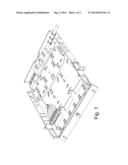
[0005] FIG. 1 shows the cabinet in the closed position.
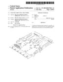
[0006] FIG. 2 shows the cabinet with the Front Tray is slid out for access.
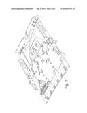
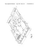
[0007] FIG. 3 shows the Rear Tray slid out, allowing access to the rear of the cabinet; even when installed between other cabinets in a rack.
DETAILED DESCRIPTION
[0008] The present invention resolves the problem by using a second sliding tray at the rear of the cabinet. This allows the cable to be securely affixed to the rear cable tray, which is held in place with guides and a latch. On releasing the latch however, the rear tray can be slid out, allowing access to the rear of the cabinet; even when installed in a rack with another cabinet in place above and below it.
[0009] Access from the front of the cabinet remains unrestricted.
[0010] Both trays can be slid entirely out of the cabinet as well. This allows for unprecedented access to the entire cabinet and convenience of servicing the cables inside, even when the cabinet has been mounted to the rack.
[0011] Rack space is becoming increasingly restricted as increased Internet traffic requires more and more data channels to be routed through existing facilities. Telecom providers are seeking to put more data channels in less space, making smaller cabinets more common. Shown in the illustrations is a 1U cabinet, which is 1.75'' tall. As a result, space inside is very restricted, and the only practical means to allow ready access the interior of a cabinet installed on a rack is with sliding trays such as shown here.
[0012] The invention consists of the sliding Rear Tray which allows for the main cable to be secured to it. In turn, the Rear Tray is fitted with latches to allow it to mount securely in place in the rackmount cabinet frame. Optionally, the Rear Tray can be further secured with additional hardware.
[0013] In one embodiment, the Rear Tray engages the sides of the Cabinet Frame and is secured from sliding with a spring operated latch. This latch is easily released to allow the Rear Tray to slide out the back of the Cabinet Frame.
[0014] The Front Tray can also be slid out the front of the cabinet (common in the industry) but it can also slide out the back of the cabinet, in conjunction with the Rear Tray. This allows both trays to be conveniently removed from the cabinet, allowing full access to install, secure, and route the cabling during installation, upgrades, service or repair.
[0015] Cable control, to prevent tangling or snagging of the cable is effected by enclosing the cable loop in spiral wrap or other similar material. This provides the right amount of flexibility to allow the cable to loop (festoon) without tangling, and yet allow the trays to slide readily.
[0016] Cable control can also be effected with the use of two hinged arms; where one end of each arm is rotatably secured to the Front Tray and Rear Tray respectively, and rotatably secured to the other arm at the other end.
[0017] Any other cable festoon management mechanism may also be employed in this application, including but not limited to linked channels, hinged arms, wire rope, trolleys, associated radius control methods and others as normally used.
[0018] The Trays can slide, or rotate on hinges or pivots, to either swing out or slide out to provide access.
[0019] Although the present invention is illustrated in connection with specific embodiments for instructional purposes, the present invention is not limited thereto. Various adaptations and modifications may be made without departing from the scope of the invention. Therefore, the spirit and scope of the appended claims should not be limited to the foregoing description.
User Contributions:
Comment about this patent or add new information about this topic:
Images included with this patent application:
 |  |
 |  |
 |
| Similar patent applications: | |
| Date | Title |
|---|---|
| 2011-06-02 | Compact media player |
| 2012-04-05 | Wireless signal receiver |
| 2014-01-16 | Container data center |
| 2014-05-29 | Container data center |
| 2014-06-19 | Wireless internet router |
| New patent applications in this class: | |
| Date | Title |
|---|---|
| 2022-05-05 | Carrier-rail bus assembly with automatic bus addressing |
| 2016-06-30 | Power supply controller for an electrical energy distribution network and method for manufacturing this controller |
| 2015-04-02 | Energy supply device for explosion-proof electronic functional units |
| 2015-02-12 | Outdoor unit of air-conditioning apparatus |
| 2015-01-29 | Enclosure power distribution architectures |
| New patent applications from these inventors: | |
| Date | Title |
|---|---|
| 2014-08-28 | Distribution panel with dual movable trays |
| Top Inventors for class "Electricity: electrical systems and devices" | |
| Rank | Inventor's name |
|---|---|
| 1 | Zheng-Heng Sun |
| 2 | Levi A. Campbell |
| 3 | Li-Ping Chen |
| 4 | Robert E. Simons |
| 5 | Richard C. Chu |