Patent application title: PIPE PICK-UP AND LAY DOWN APPARATUS
Inventors:
Alan Beck (Elk City, OK, US)
IPC8 Class: AE21B1915FI
USPC Class:
414 2258
Class name: With slope change horizontal to/from vertical pipe or rod guide
Publication date: 2014-01-30
Patent application number: 20140030045
Abstract:
A pipe pick-up and lay down apparatus for lifting and lowering materials
between a support frame and a rig floor of a workover rig, includes a
support frame, a lifting arm, a controller and a lifting assembly for
lifting and lowering the lifting arm. The lifting arm may be disposed in
a trench in the support frame table and is substantially the same length
and width as the trench and when in a lowered position. The lifting
assembly may optionally include a power supply, a plurality of cables,
and is operated by the controller to raise and lower the lifting arm.Claims:
1. A pipe pick-up and lay down apparatus for raising and lowering a
section of pipe to and from a rig, the pipe pick-up and lay down
apparatus comprising: a support frame having a table, a base, a first end
proximate the rig and a second end at a distance from the rig; a lifting
arm pivotally attached to the support frame near the first end, wherein
the lifting arm comprises a first member and a second member; and a block
and tackle system connected to the second member of the lifting arm,
wherein the block and tackle system comprises: a plurality of sheaves; a
cable; and a power source for exerting tension on the cable to raise and
lower the lifting arm.
2. The pipe pick-up and lay down apparatus of claim 1, wherein the table of the support frame includes a longitudinally extending trench sized and configured such that the first member of the lifting arm can be moved into a retracted position within the trench.
3. The pipe pick-up and lay down apparatus of claim 2, wherein the first member of the lifting arm further comprises a first end comprising a yoke.
4. The pipe pick-up and lay down apparatus of claim 3, wherein the first member of the lifting arm further comprises a roller disposed in the yoke.
5. The pipe pick-up and lay down apparatus of claim 4, wherein the yoke of the first member of the lifting arm contacts a middle portion of the section of pipe.
6. The pipe pick-up and lay down apparatus of claim 1, wherein the block and tackle system further comprises: a pneumatic cylinder, wherein the pneumatic cylinder includes a deployable rod; a first sheave attached to the deployable rod; a second sheave fixed to the support frame; a third sheave connected to the second member of the lifting arm; a fourth sheave fixed to the support frame; and wherein the cable extends from a first point on the support frame around the first, second, third and fourth sheave to a second point on the support frame.
7. The pipe pick-up and lay down apparatus of claim 6, wherein the pneumatic cylinder is connected to a source of pressurized air from the rig.
8. The pipe pick-up and lay down apparatus of claim 6, wherein the pneumatic cylinder is connected to a source of pressurized air from an independent source.
9. The pipe pick-up and lay down apparatus of claim 1, wherein the pipe pick-up and lay down apparatus further comprises a bumper stop on the table, wherein the bumper stop is removable and adjustable and positioned on the support frame table.
10. The pipe pick-up and lay down apparatus of claim 9, wherein the bumper stop comprises: a bumper first side; a plurality of springs; and a bumper second side, wherein the second side is positioned near the support frame second end, so that when the joint of pipe is lowered to the support frame table, the joint of pipe hits the bumper first side, and the plurality of springs absorb the shock from the weight of the joint of pipe.
11. The pipe pick-up and lay down apparatus of claim 1, wherein the pipe pick-up and lay down apparatus further comprises a walkway connected to the support frame table, wherein the walkway is positioned on either the support frame first side or the support frame second side and may be lowered down between the support frame table and support frame lower side when not in use.
12. The pipe pick-up and lay down apparatus of claim 1, wherein the pipe pick-up and lay down apparatus further comprises a removable pipe ramp connected to either the support frame first side or the support frame second side, and wherein the support frame can be raised and lowered relative to the position of a pipe rack located adjacent to either the support frame first side or the support frame second side to allow a joint of pipe to be moved from the pipe rack via the removable pipe ramp onto the support frame table or off of the support frame table onto the pipe rack.
13. A pipe pick-up and lay down apparatus for raising and lowering a section of pipe to and from a rig, the pipe pick-up and lay down apparatus comprising: a support frame having a table, a base, a first end proximate the rig and a second end at a distance from the rig, wherein the table includes a longitudinally extending trench; and a lifting arm pivotally attached to the support frame near the first end, wherein the lifting arm comprises a first member and a second member, wherein the first member of the lifting arm can be moved into a refracted position within the trench.
14. The pipe pick-up and lay down apparatus of claim 13, further comprising a block and tackle system connected to the second member of the lifting arm, wherein the block and tackle system comprises: a plurality of sheaves; a cable; and a power source for exerting tension on the cable to raise and lower the lifting arm.
15. The pipe pick-up and lay down apparatus of claim 13, wherein the pipe pick-up and lay down apparatus further comprises a bumper stop on the table, wherein the bumper stop is removable and adjustable and positioned on the support frame table.
16. The pipe pick-up and lay down apparatus of claim 15, wherein the bumper stop comprises: a bumper first side; a plurality of springs; and a bumper second side, wherein the second side is positioned near the support frame second end, so that when the joint of pipe is lowered to the support frame table, the joint of pipe hits the bumper first side, and the plurality of springs absorb the shock from the weight of the joint of pipe.
17. A pipe pick-up and lay down apparatus for raising and lowering a section of pipe to and from a rig, the pipe pick-up and lay down apparatus comprising: a support frame having a table, a base, a first end proximate the rig and a second end at a distance from the rig; a lifting arm pivotally attached to the support frame near the first end, wherein the lifting arm comprises a first member and a second member; and a block and tackle system connected to the second member of the lifting arm, wherein the block and tackle system comprises: a pneumatic cylinder, wherein the pneumatic cylinder includes a deployable rod; a first sheave attached to the deployable rod; a second sheave fixed to the support frame; a third sheave connected to the second member of the lifting arm; a fourth sheave fixed to the support frame; and wherein the cable extends from a first point on the support frame around the first, second, third and fourth sheave to a second point on the support frame.
18. The pipe pick-up and lay down apparatus of claim 17, wherein the pipe pick-up and lay down apparatus further comprises a bumper stop on the table, wherein the bumper stop is removable and adjustable and positioned on the support frame table.
19. The pipe pick-up and lay down apparatus of claim 18, wherein the bumper stop comprises: a bumper first side; a plurality of springs; and a bumper second side, wherein the second side is positioned near the support frame second end, so that when the joint of pipe is lowered to the support frame table, the joint of pipe hits the bumper first side, and the plurality of springs absorb the shock from the weight of the joint of pipe.
Description:
RELATED APPLICATIONS
[0001] The present application claims the benefit of U.S. Provisional Patent Application Ser. No. 61/675,200, filed Jul. 24, 2012 and entitled "Pipe Pick-Up and Lay Down Apparatus," the disclosure of which is herein incorporated by reference.
FIELD OF THE INVENTION
[0002] The present invention relates generally to pipe handling systems for handling tubular pipe and more particularly to a pipe pick-up and lay down system for workover rigs used in drilling, production and servicing operations for transferring pipe between a platform and a rig floor elevated above the platform.
BACKGROUND OF THE INVENTION
[0003] During drilling, production, and servicing of oil and gas wells, certain materials such as drill pipe, casing, and production tubing often need to be transferred between a storage platform and a rig floor. For example, during the drilling process, a drill string, composed of several individual joints of drill pipe, must sometimes be pulled out of the well bore to replace a drill bit. This process consists of removing the drill string and transferring the individual joints of pipe back to a platform located below the rig floor. An elevator or crane is used to lower the drill string from the rig to the platform. The platform is also known as a "catwalk" and is typically adjacent to a pipe rack holding multiple joints of drill pipe. After the drill bit is replaced, the process must be repeated in reverse order by transferring the pipe from the platform back onto the rig floor so that the individual pipe joints can be reconnected and ran back into the well bore. The drill pipe and other materials are extremely heavy and cumbersome and the rig floor is often 20 to 30 feet above ground floor. Accordingly, some sort of device is required to assist in the transfer of such materials from the platform to the rig floor. Numerous devices have been previously proposed for transferring pipe and other materials to and from the rig floor. Such devices are generally complex in construction, configured for use with only specific drilling rigs, and not easily transported from one drilling rig to another.
[0004] Similar to the drilling process, during the servicing of a well, several steps are required to replace production tubing or to provide maintenance or replace downhole equipment. Rigs used for servicing wells are often referred to as "workover" rigs. Workover rigs typically have a rig floor which can be positioned over a well and the well's surface equipment. Workover rigs also generally have a mast which supports elevators used to raise and lower production tubing and handle individual joints of pipe used in the well bore. The rig floor of a workover rig is often elevated as much as 6 to 15 feet above ground level. Typically, the practice with workover rigs has been to manually transfer the pipe between the rig floor and a pipe rack located to the side of the platform. Thus, to lift a joint of pipe to the rig floor, a joint of drill pipe is rolled from the pipe rack to the platform where a worker manually lifts one end of the pipe off of the platform to a height at which the elevator of the rig can be latched onto the end of the pipe. This process is then reversed for removing the joints of pipe from the rig floor back onto the platform.
[0005] Because of the manual labor involved and the weight and cumbersome nature of the drill pipe and other materials being transferred, the practice of transferring drill pipe from the platform to the rig floor, or from the rig floor to the platform, is extremely dangerous and labor intensive. Therefore, there is a need for a simple operation for transferring pipe up between the rig elevators and the platform or down between the platform and the rig elevators. It is to these and other deficiencies in the prior art that the present invention is directed.
SUMMARY OF THE INVENTION
[0006] In preferred embodiments, the present invention provides an apparatus for easily transferring pipe and other materials from a platform to a rig floor of a workover rig elevated above the platform. The apparatus includes a support frame, a lifting arm, a lifting assembly and a controller. The support frame includes a trench disposed in its table which is substantially the same length and shape as the lifting arm. When the lifting arm is in a lowered position, the lifting arm is on the same plane as the table of the support frame.
[0007] The lifting arm may consist of a first member, a second member and a pivot point. The first member of the lifting arm includes a first end which may include a yoke and a roller. The lifting assembly may consist of a block and tackle system and include a plurality of sheaves, a cable and a power supply.
[0008] In another preferred embodiment, the present invention may include a bumper stop so that when the pipe is slid toward an end of the support frame, the bumper stop operates to absorb the shock and weight of the joint of pipe and stop the joint of pipe from sliding too far. Additionally, the present invention may include a stairway with a handrail for access to the table of the support frame. A walkway may be connected to the table of the support frame and may include a handrail which may be folded down toward a side of the support frame. The support frame may also include a removable pipe ramp so that the joint of pipe may easily be rolled from the pipe rack onto the support frame.
BRIEF DESCRIPTION OF THE DRAWINGS
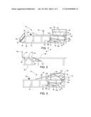
[0009] FIG. 1 is a side view of a pipe pick-up and lay down apparatus having a lifting arm in a lowered position and positioned in front of a workover rig.
[0010] FIG. 2 is a front view of the pipe pick-up and lay down apparatus of FIG. 1 illustrating a trench in which the lifting arm is disposed when in a lowered position and showing the pipe pick-up and lay down apparatus positioned adjacent to a pipe rack.
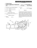
[0011] FIG. 3 is a side view of the pipe pick-up and lay down apparatus of FIG. 1 shown with the lifting arm in a raised position and positioned in front of a workover rig.
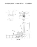
[0012] FIG. 4 is a front view of one end of the lifting arm showing a yoke and a roller.
[0013] FIG. 5 is a top view of the bumper stop positioned on the table of the support frame.
[0014] FIG. 6 is a side view of the pipe pick-up and lay down apparatus of FIG. 1 next to a workover rig.
DETAILED DESCRIPTION OF PREFERRED EMBODIMENTS
[0015] Referring to FIG. 1, and generally to FIGS. 1-3, shown therein is an embodiment of a pipe pick-up and lay down apparatus 10. The pipe pick-up and lay down apparatus 10 includes a support frame 12, a lifting arm 14, a block and tackle system 16, and a controller 18.
[0016] The support frame 12 has a first end 22, a second end 24, a first side 26, a second side 28, an table 30, and a base 32. The support frame 12 is constructed of a plurality of tubular members interconnected to one another in a suitable manner, such as by welding. The support frame 12 may also include a stairway 34 (FIG. 1) with a stairway handrail 35 to provide a worker with easy accessibility to the table 30 of the support frame 12. A walkway 36 is connected to the table 30 of the support frame 12 and may be positioned on either the first side 26 or the second side 28 of the support frame 12. The walkway 36 may be folded down toward the first side 26 or the second side 28 of the support frame 12 when not in use.
[0017] The controller 18 is positioned on the table 30 of the support frame 12. Alternatively, the controller 18 is configured for remote operation. As further shown in FIG. 2, a handrail 20 is positioned on the walkway 36 and is removable to allow the support frame 12 to be positioned next to a pipe rack 38 and to allow a joint of pipe 40 to be rolled from the support frame 12 to the pipe rack 38 which may be positioned on either the first side 26 or the second side 28 of the support frame 12. In a preferred embodiment, the pipe pick-up and lay down apparatus 10 can be raised or lowered relative to the position of the pipe rack 38 so that multiple layers of pipe may be stored on the pipe rack 38. In a presently preferred embodiment, the support frame 12 can be raised or lowered using telescoping tubular members that are mechanically, hydraulically or pneumatically raised and lowered.
[0018] A removable pipe ramp 42 may be attached to the first side 26 or the second side 28 of the support frame 12 in various positions to assist in rolling the joint of pipe 40 onto the pipe rack 38. The pipe ramp 42 is configured to facilitate the movement of pipe from the pipe pick-up and lay down apparatus 10 to the pipe rack 38 or from the pipe rack 38 to the pipe pick-up and lay down apparatus 10 regardless of their relative vertical positions.
[0019] Referring to FIGS. 1-3, the support frame 12 further includes a trench 44 disposed in the table 30 of the support frame 12. The trench 44 has a first end 46 and a second end 48. The trench 44 extends along the table 30 of the support frame 12 near the first end 22 of the support frame 12 and is configured to substantially correspond with the shape and size of the lifting arm 14.
[0020] As shown in FIGS. 1 and 3, the lifting arm 14 consists of a first member 50 and a second member 52. The first member 50 is connected to the second member 52 at a pivot point 54. The first member 50 is substantially perpendicular to the second member 52. The lifting arm 14 is constructed of a plurality of tubular members interconnected to one another in a suitable manner, such as by welding. The pivot point 54 of the lifting arm 14 is secured to the table 30 of the support frame 12 at the first end 46 of the trench 44. As further shown in FIG. 1, when the lifting arm 14 is in its lowered position, the first member 50 of the lifting arm 14 is fully disposed in the trench 44, and is substantially level with the table 30 of the support frame 12.
[0021] Referring now to FIG. 4, shown is a first end 56 of the first member 50 of the lifting arm 14, which consists of a yoke 58 and an optional roller 60. As shown in FIG. 3, when the lifting arm 14 is in the raised position, the joint of pipe 40 is positioned in the yoke 58 of the first end 56 of the first member 50 of the lifting arm 14.
[0022] Now referring to FIG. 5, shown is a bumper stop 62 which is removable and adjustable and consists of a first side 64, a plurality of springs 66 and a second side 68. The second side 68 of the bumper stop 62 is positioned near the second end 22 of the support frame 12. When a joint of pipe 40 is lowered to the table 30 of the support frame 12, the joint of pipe 40 hits the first side 64 of the bumper stop 62, which absorbs shock from the weight of the joint of pipe 40 via the plurality of springs 66. The bumper stop 62 can be installed at different locations on the support frame 12 to accommodate different lengths of pipe 40.
[0023] Returning now to FIGS. 1 and 3, the block and tackle system 16 is positioned between the table 30 and the base 32 of the support frame 12. The block and tackle system 16 has been removed from FIG. 2 for clarity. The block and tackle system 16 consists of a plurality of sheaves 70 (70a, 70b, 70c and 70d), a cable 72 and a pneumatic cylinder 74. Generally, the block and tackle system 16 is configured to controllably raise and lower the lifting arm 14.
[0024] The pneumatic cylinder 74 includes a rod 78 that extends and retracts in response to application of pressure to the pneumatic cylinder 74. The pneumatic cylinder 74 is connected to an air supply 76. In a preferred embodiment, the air supply 76 is connected to an external supply of pressurized air from the workover rig or other nearby equipment. The pneumatic cylinder 74 is connected to and controlled by the controller 18.
[0025] In a presently preferred embodiment, the cable 72 is rigidly fixed on both ends to the support frame 12 and is routed around each of the plurality of sheaves 70. Sheave 70a is supported on the rod 78, sheave 70b is positioned on the support frame 12 behind the pneumatic cylinder 74, sheave 70c is positioned on the second member 52 on the lifting arm 14 and sheave 70d is positioned on the support frame 12 above sheave 70c. As the air pressure in the pneumatic cylinder 74 increases, the rod 78 and sheave 70a are extended, thereby increasing the distance between sheaves 70a and 70b and exerting tension on the cable 72. As the cable 72 is tensioned, the sheave 70c and the second member 52 move in the direction of sheave 70d, thereby causing the lifting arm 14 to pivot and the first member 50 is raised.
[0026] When the pressure in the pneumatic cylinder 74 is decreased, the weight carried by the lifting arm 14 causes the lifting arm 14 to pivot and increase the distance between sheave 70c and sheave 70d. As the lifting arm 14 retracts, the cable 72 pulls sheave 70a and rod 78 into a retracted position within the pneumatic cylinder 74. Thus, the block and tackle system 16 functions to move the lifting arm 14 from a lowered position (FIG. 1) to a raised position (FIG. 3) via the cable 72 and the plurality of sheaves 70 by controllably extending and retracting the rod 78.
[0027] The use of multiple sheaves 70 increases the mechanical advantage of the pneumatic cylinder 74 and cable 72. Although the use of a single-acting pneumatic cylinder has been described herein, the use of dual-acting pneumatic cylinder is also contemplated. The ability to forcefully retract the pneumatic cylinder 74 may be particularly useful in applications where the weight of the lifting arm is insufficient to efficiently force the depressurized pneumatic cylinder 74 into a retracted position. It will also be understood that although a pneumatic cylinder is presently preferred, the lifting arm 14 may be raised and lowered using other suitable mechanical or hydraulic devices.
[0028] Turning to FIG. 6, shown therein is a depiction of the pipe pick-up and lay down apparatus 10 positioned near a workover rig 82. The workover rig 82 includes a rig floor 84 elevated a distance above the table 30 of the support frame 12. The workover rig 82 also includes an elevator 86 for lowering the joint of pipe 40 onto a pipe catch bar 88 which is connected to a lower portion 90 of the workover rig 82 and which is elevated slightly above the table 30 of the support frame 12.
[0029] To raise the joint of pipe 40 from the table 30 of the support frame 12 to the rig floor 84 of the workover rig 82, the pipe pick-up and lay down apparatus 10 uses the block and tackle system 16 to raise the lifting arm 14 holding the joint of pipe 40 in the yoke 58 of the first end 56 of the first member 50 of the lifting arm 14. In this way, the lifting arm 14 is configured to raise the joint of pipe 40 by supporting a middle portion of the joint of pipe 40 within the yoke 58. Once the joint of pipe 40 is lifted by the lifting arm 14 a worker can move the joint of pipe 58 forward slightly via the roller 60 located on the first end 56 of the first member 50 of the lifting arm 14, or manually without the roller 60, so that the joint of pipe 40 is supported by the pipe catch bar 88. Once the pipe 40 is supported by the pipe catch bar 88, the lifting arm 14 can be retracted and the pipe 40 can be connected to the elevator 86 of the workover rig 82 and lifted to the rig floor 84.
[0030] To lower a joint of pipe 40 from the rig floor 84 of the workover rig 82 onto the table 30 of the support frame 12, the elevator 86 of the workover rig 82 lowers the joint of pipe 40 and a worker walks the joint of pipe 40 toward the bumper stop 62 and the second end 24 of the support frame 12. Next, the joint of pipe 40 is disconnected from the elevator 86 of the workover rig 82 and dropped slightly onto the pipe catch bar 88. Next, the pipe pick-up and lay down apparatus 10 uses the block and tackle system 16 to raise the lifting arm 14 which lifts the joint of pipe 40 slightly via the yoke 58 of the first end 56 of the first member 50 of the lifting arm 14. In this way, the lifting arm 14 is configured to raise the joint of pipe 40 by supporting a middle portion of the joint of pipe 40 within the yoke 58.
[0031] Once the joint of pipe 40 is lifted up off of the pipe catch bar 88, a worker moves the joint of pipe 40 slightly towards the second end 24 of the support frame 12 via the roller 60 located on the first end 56 of the first member 50 of the lifting arm 14, or manually without the roller 60, so that when the lifting arm 14 is in a fully lowered position (FIG. 1), the entire joint of pipe 40 will be located on top of the table 30 of the support frame 12. The bumper stop 62 may be positioned on the table 30 of the support frame 12 towards the second end 24 of the support frame 12 to absorb the shock of the joint of pipe 40 when it is laid down on the table 30 of the support frame. A worker can then roll the joint of pipe 40 onto the pipe rack 38.
[0032] It is to be understood that even though numerous characteristics and advantages of various embodiments of the present invention have been set forth in the foregoing description, together with details of the structure and functions of various embodiments of the invention, this disclosure is illustrative only, and changes may be made in detail, especially in matters of structure and arrangement of parts within the principles of the present invention to the full extent indicated by the broad general meaning of the terms expressed herein and in the appended claims. It will be appreciated by those skilled in the art that the teachings of the present invention can be applied to other systems without departing from the scope and spirit of the present invention.
User Contributions:
Comment about this patent or add new information about this topic:
Images included with this patent application:
 |  |
 |
| Similar patent applications: | |
| Date | Title |
|---|---|
| 2014-04-03 | Vehicular loading apparatus |
| 2014-03-27 | Occupant transfer apparatus for vehicle |
| 2009-04-30 | Bag supply apparatus |
| 2013-03-28 | Cargo lift apparatus |
| 2013-11-07 | Hook lift jib apparatus |
| New patent applications in this class: | |
| Date | Title |
|---|---|
| 2013-12-26 | Automated pipe feed mechanism and method |
| 2012-02-02 | Pipe-handling apparatus and methods |
| 2011-05-05 | Pipe stabilizer for pipe section guide system |
| 2009-08-06 | Pipe handling apparatus and methods |
| Top Inventors for class "Material or article handling" | |
| Rank | Inventor's name |
|---|---|
| 1 | Christopher Hofmeister |
| 2 | Peter Van Der Meulen |
| 3 | Jeffrey C. Hudgens |
| 4 | John Oren |
| 5 | Martin Hosek |