Patent application title: POWER SAW WITH MITER ANGLE ADJUSTMENT
Inventors:
Jonathan Buckner Morgan
Robert Lee Owens
IPC8 Class: AB23D4704FI
USPC Class:
834686
Class name: With work immobilizer work-stop abutment retractable
Publication date: 2013-06-13
Patent application number: 20130145913
Abstract:
This specification discloses a mechanism that alters the cutting angle of
a motorized miter saw. The cutting angle is altered by a mechanism that
deploys a member from within or behind the fence to a position in front
of the fence parallel to the blade and partially within a cavity/opening
in the material resting surface. When deployed in front of the fence, the
angle between the blade and cutting material is altered.Claims:
1) A power saw comprising: a motor, a motor housing, a blade driven by
said motor, a resting surface for supporting a cutting material wherein
said motor, said motor housing, and said blade are disposed above said
resting surface, said resting surface including an elongated slot for
passing the blade therethrough, a fence for further positioning said
cutting material, at least one cavity or at least one opening in said
resting surface disposed in the proximity of said elongated slot, at
least one elongated member being positionable from a non-operating
position deposed within or behind said fence to an operating position
wherein said at least one elongated member is disposed substantially
parallel to said elongated slot and partially in said at least one cavity
or partially in said at least one opening such that a portion of said at
least one elongated member extends above said resting surface to alter an
angle between said blade and said cutting material.
2) The power saw of claim 1 wherein said at least one elongated member is defined by a bar and said at least one cavity or said at least one opening is defined by a channel allowing said bar to slide in said channel from said non-operating position to said operating position.
3) The power saw of claim 2 where said bar is held captive in said channel by said bar and said channel having similar profiles with said bar and said channel being wider for a portion of the interior of said channel.
4) The power saw of claim 2 wherein said channel is sloped relative to said resting surface and said bar is shaped such that the surface of said bar that interfaces with said cutting material remains parallel or approximately parallel to said resting surface as said bar slides in said channel wherein said bar slides from a position below said resting surface to a plurality of positions above said resting surface.
5) The power saw of claim 4 wherein said bar is held captive in said channel by said bar and said channel having similar profiles with said bar and said channel being wider for a portion of the interior of said channel.
6) The power saw of claim 1 wherein said at least one elongated member is positioned via rotating said at least one elongated member about a hinge from a said non-operating position to a said operating position.
7) The power saw of claim 6 wherein said at least one elongated member when positioned in said operating position rests in a channel.
8) The power saw of claim 6 wherein said hinge is positioned within or behind said fence.
9) The power saw of claim 8 wherein said at least one elongated member when positioned in said operating position rests in a channel.
10) The power saw of claim 1 wherein said at least one elongated member can be extended in the direction or approximate direction of said cutting material via a plurality of removable attachments comprising a plurality of thicknesses which would increase the thickness of said at least one elongated member.
Description:
CROSS REFERENCE TO RELATED APPLICATIONS
[0001] This is a division application of application Ser. No. 12/321,145, Filed Jan. 21, 2009.
FEDERALLY SPONSORED RESEARCH
[0002] Not Applicable
SEQUENCE LISTING OR PROGRAM
[0003] Not Applicable
BACKGROUND OF THE INVENTION
[0004] 1. Field of Invention
[0005] This invention relates to power saws; specifically, power saws capable of making miter angle adjustments.
[0006] 2. Background of the Invention
[0007] When trimming windows, doorways, and the like, there are typically two vertical pieces of trim boards, a horizontal trim board at the top, and for widows a couple of boards for the sill. Consider where the vertical pieces intersect the horizontal piece. At the intersection, each of the boards would have to be cut at a 45 degree angle. Professional carpenters want the boards to meet in such a manner that the vertical and horizontal boards look almost like one piece. This can be achieved by raising the board off of the miter saw base by a small amount when making the 45 degree cut. Typically, a professional carpenter would put a portion of a pencil or other similar item under the board to raise it slightly when making the 45 degree cut. Therefore, when the boards are put in place, this results in the horizontal board and vertical board contacting on an edge instead of complete contact on the adjoining surfaces. The edge is the edge that is visible when looking at the window framing. Because of this edge type contact, the boards look as if they are almost one board.
[0008] Miter saws have an adjustment that can produce the same type cut without using a pencil or similar item as an offset; however the adjustment is time consuming. On most miter saws, one would have to reach behind the saw and rotate a knob, tilt the saw head, and tighten the knob. For a professional carpenter, the time to do this is prohibitive. One saw manufacturer makes a saw which allows the adjustment to be made from the front of the saw. Even so, making the adjustment is time consuming. Additionally, because of the mass of the saw motor, making the adjustment quickly is awkward. Once the adjustment was made, it would be easy to not notice it, which would result in incorrect cuts when making trimming cuts other than the one described above, or worse yet when making framing cuts.
OBJECTS AND ADVANTAGES
[0009] This invention remedies the previously mentioned problems by providing a power saw with a miter angle adjustment specifically designed for trimming applications.
[0010] The power saw with miter angle adjustment has the following advantages:
[0011] a) Makes an adjustment in the miter angle such that trimming pieces will adjoin on an edge.
[0012] b) Provides a way to make the adjustment very quickly.
[0013] c) Provides a way to remove the adjustment very quickly.
[0014] d) Makes it clear whether the adjustment is or is not in place.
SUMMARY
[0015] In accordance with the present invention, a power saw with a miter angle adjustment.
DRAWINGS
Figures
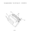
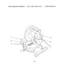
[0016] FIG. 1 shows an isometric view of a miter saw with the offset that produces the miter angle adjustment.
[0017] FIG. 2 shows an isometric view of a table saw with the offset that produces the miter angle adjustment.
[0018] FIG. 3 shows an isometric view of a skill saw with the offset that produces the miter angle adjustment.
[0019] FIG. 4 shows an isometric view of a jig saw with the offset that produces the miter angle adjustment.
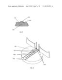
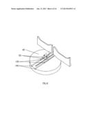
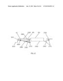
[0020] FIG. 5 shows an isometric view of a rack and pinion system that positions the offset.
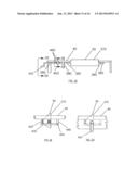
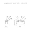
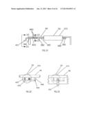
[0021] FIG. 6 shows an isometric view of a bar sliding in a channel that positions the offset.
[0022] FIG. 7 shows a section view of the bar that slides in a channel.
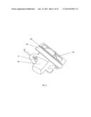
[0023] FIG. 8 shows an isometric view of a bar that rotates into a channel to position the offset.
[0024] FIG. 9 shows a section view of the bar that rotates into a channel.
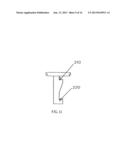
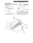
[0025] FIG. 10 shows a front view of a bar that rotates from underneath to position the offset.
[0026] FIG. 11 shows a left side view of a bar that rotates from underneath.
[0027] FIG. 12 shows a front view of a four bar mechanism that positions the, offset where the mechanism is positioned via a thread rod.
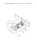
[0028] FIG. 13 shows a front view of a four bar mechanism that positions the offset where the mechanism is positioned via a latch.
[0029] FIG. 14 shows a section view of a four bar mechanism that positions the offset where the mechanism is positioned via a latch.
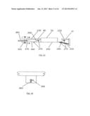
[0030] FIG. 15 shows a 2 dimensional view of a rectangular-shaped rotating bar that positions the offset.
[0031] FIG. 16 shows the first section view of a rectangular-shaped rotating bar that positions the offset.
[0032] FIG. 17 shows the left side view of a rectangular-shaped rotating bar that positions the offset.
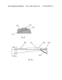
[0033] FIG. 18 shows a 2 dimensional view of a triangular-shaped rotating bar that positions the offset.
[0034] FIG. 19 shows the first section view of a triangular-shaped rotating bar that positions the offset.
[0035] FIG. 20 shows the left side view of a triangular-shaped rotating bar that positions the offset.
[0036] FIG. 21 shows a 2 dimensional view of a circular-shaped rotating bar that positions the offset.
[0037] FIG. 22 shows the first section view of a circular-shaped rotating bar that positions the offset.
[0038] FIG. 23 shows the left side view of a circular-shaped rotating bar that positions the offset.
[0039] FIG. 24 shows a 2 dimensional view of an oval-shaped rotating bar that positions the offset.
[0040] FIG. 25 shows the first section view of an oval-shaped rotating bar that positions the offset.
[0041] FIG. 26 shows the left side view of an oval-shaped rotating bar that positions the offset.
[0042] FIG. 27 shows a 2 dimensional view of an attachment that repositions the offset.
[0043] FIG. 28 shows the left side view of an attachment that repositions the offset.
REFERENCE NUMERALS
[0044] 10 power saw
[0045] 20 power saw motor
[0046] 30 power saw blade
[0047] 40 cutting material resting surface
[0048] 50 offset
[0049] 60 saw embodiment with rack and pinion offset positioning
[0050] 70 rack
[0051] 80 pinion
[0052] 90 rack and pinion supporting structure
[0053] 100 bracket
[0054] 110 shaft
[0055] 120 handle
[0056] 130 sliding bar
[0057] 140 channel for sliding bar
[0058] 150 rotating bar
[0059] 160 hinge
[0060] 170 rotating bar channel
[0061] 180 offset defining structure
[0062] 190 hinge
[0063] 200 spring
[0064] 210 first positioning surface
[0065] 220 second positioning surface
[0066] 230 bar 1 of the four bar mechanism
[0067] 240 bar 2 of the four bar mechanism
[0068] 250 bar 3 of the four bar mechanism
[0069] 260 bar 4 of the four bar mechanism
[0070] 270 rotational joint
[0071] 280 rotational joint with a threaded receptor
[0072] 290 threaded rod
[0073] 300 universal joint
[0074] 310 structure positioning handle
[0075] 320 handle
[0076] 330 spring
[0077] 340 restraining link
[0078] 350 structure positioning latch
[0079] 360 latch
[0080] 365 latch keyhole
[0081] 370 structure defining offset
[0082] 380 shaft
[0083] 390 shaft bearings
[0084] 400 shaft restrainer
[0085] 410 handle
[0086] 420 spring
[0087] 430 horizontal restraining member
[0088] 440 vertical structural member
[0089] 450 hinge
[0090] 460 rectangular portion of shaft
[0091] 470 Offset prior to adding attachment that extends the offset
[0092] 480 Attachment for extending offset
[0093] 490 Screw
DETAILED DESCRIPTION
FIGS. 1-4
Preferred Embodiment
[0094] This invention, at a minimum, applies to four types of saws as illustrated in the Figures listed below:
[0095] Miter Saw: FIG. 1
[0096] Table Saw: FIG. 2
[0097] Skill Saw: FIG. 3
[0098] Jig Saw: FIG. 4
[0099] In FIGS. 1 thru 4 the saw 10 has a motor 20, a cutting blade 30, a cutting material resting surface 40, and an offset 50, wherein the offset changes the cutting angle between the cutting blade 30 and the cutting material (not shown).
[0100] A preferred embodiment of the saw of the present invention is illustrated in FIG. 5 wherein the offset 50 is positioned via a rack 70 and a pinion 80. The pinion 80 is connected to a shaft 110 that is positioned by a bracket 100 that is connected to the supporting structure 90. The shaft 110 is connected to the handle 120 where rotation of the handle 120 rotates the shaft 110 which rotates the pinion 80 which moves the offset 50 relative to the cutting material resting surface 40. This results in the offset 50 moving from a position below the cutting material resting surface 40 to a plurality of positions above the cutting material resting surface 40.
FIGS. 6-7
Alternate Embodiment
[0101] An alternate embodiment of the saw of the present invention is illustrated in FIG. 6 (isometric view) and FIG. 7 (section view), where the offset 50 is defined via a sliding bar 130 that slides in a channel 140. Referring to FIG. 7, notice that the bar 130 is held captive in the channel 140 due to the bar 130 and the channel 140 being wider at the innermost portions. The bar 130 can slide to a position that would engage the cutting material (not shown) to a position that would be clear of the cutting material.
FIGS. 8-9
Alternate Embodiment
[0102] An alternate embodiment of the saw of the present invention is illustrated in FIG. 8 (isometric view) and FIG. 9 (section view), where the offset 50 is defined via a rotating bar 150 that rotates about a hinge 160 from a position in the channel 170 to a position (as represented by the dashed lines) clear of the cutting material resting surface 40 and thus clear of the cutting material (not shown). Referring to FIG. 9, notice that the bar 150 can rotate into the channel 170 because the channel 170 and the bar 150 are shaped such that the bar 150 is not held captive by the channel 170.
FIGS. 10-11
Alternate Embodiment
[0103] An alternate embodiment of the saw of the present invention is illustrated in FIG. 10 (isometric view) and FIG. 11 (left view), where the offset 50 is defined via an offset defining structure 180 that rotates about a hinge 190 constrained either by the first positioning surface 210 or by the second positioning surface 220, wherein the spring 200 holds the offset defining structure 180 on the positioning surfaces (210, 220). When the offset defining structure 180 is positioned via the first positioning surface 210, then the offset 50 would engage the cutting material (not shown). When the offset defining structure 180 is positioned via the second positioning surface 220, then the offset 50 would not engage the cutting material.
FIG. 12
Alternate Embodiment
[0104] An alternate embodiment of the saw of the present invention is illustrated in FIG. 12 (two dimensional view), where the offset 50 is positioned via a four bar mechanism. The first bar 230 is defined by the structure of the saw 10, bar two 240 is connected on one end to bar one 230 and on the other end to bar three 250, the other end of bar three 250 is connected to bar four 260, and the other end of bar four 260 is connected to bar one 230. The bars are connected via three rotational joints 270 and one rotational joint with a threaded receptor 280. When the handle 320 is rotated, the universal joint 300 rotates, which rotates the threaded rod 290 which interfaces with the rotational joint with a threaded receptor 280. This rotation results in the positioning of the four bar mechanism such that the offset 50 is positioned at a plurality of positions below the cutting material resting surface 40 to a plurality of positions above the cutting material resting surface 40.
FIGS. 13-14
Alternate Embodiment
[0105] An alternate embodiment of the saw of the present invention is illustrated in FIG. 13 (two dimensional view) and FIG. 14 (section view), where the offset 50 is positioned via a four bar mechanism. The first bar 230 is defined by the structure of the saw 10, bar two 240 is connected on one end to bar 230 and on the other end to bar three 250, the other end of bar three 250 is connected to bar four 260, and the other end of bar four 260 is connected to bar one 230. The bars are connected via four rotational joints 270. The four bar mechanism is positioned via a latch 360 that is connected to a connecting link 340 that is attached to the four bar mechanism. When the latch 360 is rotated one way it slides through a key hole 370 in the structure 350 positioning the latch 360. The latch 360 is restrained via a spring 330. Depending on the engagement of the latch, the four bar mechanism is positioned such that the offset 50 is either above the cutting material resting surface 40 or below the cutting material resting surface 40.
FIGS. 15-17
Alternate Embodiment
[0106] An alternate embodiment of the saw of the present invention is illustrated in FIG. 15 (two dimensional view), FIG. 16 (section view) and FIG. 17 (left side view), where the offset 50 is positioned via a structural member 370 that is attached to the shaft 380 that is held in place via bearings 390 such that when the shaft 380 is rotated to one position, the offset 50 is above the cutting material resting surface 40 and when the shaft 380 is rotated to another position, the offset 50 is below the cutting material resting surface 40. The shaft 380 would be held in position via the horizontal restraining member 430 interfacing with the rectangular portion 460 of the shaft 390. The horizontal restraining member 430 pivots about the hinge 450 that is attached to the vertical structural member 440. The spring 420 forces the horizontal restraining member 430 against the rectangular portion 460 of the shaft 390 which fixes the shaft 390 in place.
Operation
FIGS. 5-17
[0107] The operation of the saw of the present invention entails moving the offset 50 from a position below the cutting material resting surface 40 to a position above the cutting material resting surface 40 and vice versa via the mechanisms depicted in FIGS. 5-17. The positioning of the offset affects the miter cutting angle. A carpenter might make several cuts where the change in the miter angle is needed, and then reposition the offset 50 such that no change in miter angle would occur.
Advantages
[0108] Based on the description above, the advantages of the saw of the present invention follow: The power saw with miter angle adjustment has the following advantages:
[0109] a) This invention provides a way for a carpenter to quickly make a small miter angle change and to quickly remove the miter angle change. The change in miter angle is very precise (i.e. the same change every time).
[0110] b) This invention makes it very clear that the miter angle adjustment is or is not in place.
[0111] c) This invention greatly improves the ability of a professional carpenter to make consistent high quality cuts where the adjoining boards contact on edge.
[0112] d) This invention does not impede in any way the normal use of the saw when the miter angle adjustment is not in place.
CONCLUSIONS, RAMIFICATIONS, AND SCOPE
[0113] This invention provides a saw that allows small adjustments in miter angles to be made quickly and precisely. Additionally, this invention makes it very clear whether the adjustment is or is not in place.
[0114] Although the description above contains many specifics, these should not be construed as limiting the scope of the invention but as merely providing illustrations of some of the presently preferred embodiments of this invention. For example, there are many ways to hold a four bar mechanism in place, most if not all of which would be applicable to this invention. Additionally, there are many ways to constrain a shaft that rotates as well as many ways to configure and implement a rack and pinion system. In general, there are many ways to position an offset that would be applicable to this invention. The important characterizing feature is that the offset is positioned.
User Contributions:
Comment about this patent or add new information about this topic:
| People who visited this patent also read: | |
| Patent application number | Title |
|---|---|
| 20220050380 | APPARATUS AND METHOD FOR EXPOSING PRINTING PLATES USING LIGHT EMITTING DIODES |
| 20220050379 | MATERIAL FOR FORMING UNDERLAYER FILM, RESIST UNDERLAYER FILM, AND LAMINATE |
| 20220050378 | POSITIVE RESIST MATERIAL AND PATTERNING PROCESS |
| 20220050377 | DIFFRACTIVE BACKLIGHT FABRICATION METHOD |
| 20220050376 | METHOD OF FORMING MASK INCLUDING CURVILINEAR SHAPE AND METHOD OF FORMING SEMICONDUCTOR DEVICE |
Images included with this patent application:
 |  |
 |  |
 |  |
 |  |
 |  |
 |  |
 |  |
 |  |
 |  |
| Similar patent applications: | |
| Date | Title |
|---|---|
| 2012-12-27 | Table saw with mechanical fuse |
| 2013-04-04 | Power saw miter cutting guide |
| 2010-10-07 | Power saw miter guide |
| 2012-05-17 | Miter saw with working lamp |
| 2012-10-04 | Power saw miter guide |
| New patent applications in this class: | |
| Date | Title |
|---|---|
| 2011-08-04 | Repetitive stroke work system |
| Top Inventors for class "Cutting" | |
| Rank | Inventor's name |
|---|---|
| 1 | Stephen F. Gass |
| 2 | Stephen F. Gass |
| 3 | Toshiyuki Kani |
| 4 | Andrew Frolov |
| 5 | J. David Fulmer |